bürkert 2000 Wartungs- Und Reparaturanleitung
Vorschau ausblenden
Andere Handbücher für 2000:
- Umbauanleitung (117 Seiten) ,
- Bedienungsanleitung (94 Seiten) ,
- Montageanleitung (88 Seiten)
Inhaltsverzeichnis
Verfügbare Sprachen
Verfügbare Sprachen
Quicklinks
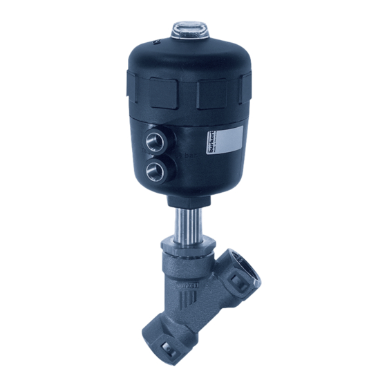
Type 2000 / 2002
Replacement of Valve Kits and Seal Kits
Wechseln von Ventil- und Dichtungssätzen
Maintenance and Repair Instructions
Wartungs- und Reparaturanleitung
Unit 173 Argyle Industrial Estate, Argyle Street, Nechells, Birmingham B7 5TE
www.pneutrolfluidcontrol.com sales@pneutrol.com
Pneutrol International Limited
Tel: +44 (0) 1213287288
Kapitel
Inhaltsverzeichnis

Verwandte Anleitungen für bürkert 2000


Inhaltszusammenfassung für bürkert 2000
- Seite 21 Steuerfunktion A (SFA) ..................26 5.2 Wechsel des Dichtungssatzes bei Antrieb mit Steuerfunktion B und I (SFB / SFI) ..............30 6 werkzeugsätze........................34 6.1 Montageschlüssel ......................34 6.2 Montagehülsen ......................35 7 empfohlene hIlfsstoffe ....................36 7.1 Produktbezeichnungen und Hersteller: ..............36 2000/2002 - 19...
-
Seite 22: Diese Anleitung
1 DIese anleItung Die Umbauanleitung beschreibt die Vorgehensweise für den Wechsel von Ventil- und Dichtungssätzen der Prozessventile Typ 2000 und 2002. Bewahren Sie diese Anleitung so auf, dass sie für jeden Benutzer gut zu- gänglich ist und jedem neuen Eigentümer des Gerätes wieder zur Verfügung steht. -
Seite 23: Allgemeine Sicherheitshinweise
2. allgemeIne sIcherheItshInweIse hInweIs! Die Prozessventile der Typen 2000 und 2002 wurden unter Einbeziehung der anerkannten sicherheitstechnischen Re- geln entwickelt und entsprechen dem Stand der Technik. Trotzdem können Gefahren entstehen. Betreiben Sie die Ventile nur in einwandfreiem Zustand und unter Beachtung der Betriebsanleitung. -
Seite 24: Teilebezeichnung
3 teIlebezeIchnung Steuerfunktion A (SFA) Steuerfunktion B (SFB) 22 - 2000/2002... - Seite 25 Spindel Pendelteller Dichtring Nippel Abstreifer (zu Stopfbuchsensatz) Rohr Verstärkungsring O-Ring Laufbuchse Stopfbuchsensatz einschließlich Pos. 7 und Pos. 39 Tellerfeder Schraube Füllkörper Zwischenscheibe O-Ring Kolben Kolbendichtung Stützscheibe Mutter Stellungsanzeige Druckfeder Druckfeder O-Ring Deckel O-Ring Druckfeder zu Stopfbuchsensatz Scheibe 2000/2002 - 23...
-
Seite 26: Ventilsatz Wechseln
• Neue Graphit-Dichtung (Pos. 5) einle- gen. • nur bei Va-gehäuse: Nippelgewinde (Pos. 6) mit "Klüberpaste UH1 96-402" einfetten. • nur bei typ 2002: Dichtungsband verwenden. • Ventilantrieb mit Nippel fest in das Gehäuse einschrauben. VorsIcht! Beachten Sie das Drehmoment (siehe Tabelle) 24 - 2000/2002... - Seite 27 • Nur bei SFA: Deckel (Pos. 31) mit Spezialschlüssel wieder fest verschrauben. • Ventil auf Funktion und Dichtheit prüfen. Tabelle: Ventilsätze Va-gehäuse rg-gehäuse typ 2000 / 2002 typ 2000 / 2002 ptfe- fkm- ptfe- fkm- Dichtung Dichtung Dichtung Dichtung best.- nr.
-
Seite 28: Dichtungssatz Wechseln
• nur bei antriebsgröße g-100 und h-125 mm: Scheibe (Pos. 40) entnehmen. • Druckfedern (Pos. 28, 29) entnehmen. • Stellungsanzeige (Pos.26) mit Innen- sechkantschlüssel demontieren. • Antrieb am Nippel (Pos. 6) aus Ventil- gehäuse (Pos. 1) schrauben. 26 - 2000/2002... - Seite 29 (pos. 18) sofort wieder entfernen. • Laufbuchse (Pos. 12), Tellerfedern (Pos. 17) und Schraube (Pos. 18) auf Rohr (Pos. 8) aufsetzen. • Schraube (Pos. 18) mit Steckschlüssel fest verschrauben; dabei auf zen- trische Lage der Tellerfedern (Pos. 17) achten. 2000/2002 - 27...
- Seite 30 • nur bei antriebsgröße g-100 / h-125: Scheibe (Pos. 40) einsetzen. • O-Ring (Pos. 32) wechseln, dazu Klarsichthaube abschrauben. • Deckelgewinde leicht einfetten (Fett wie bei Laufbuchse). • Deckel (Pos. 31) aufsetzen und mit Spezialschlüssel festschrauben. • Ventil auf Funktion und Dichtheit prüfen. 28 - 2000/2002...
- Seite 31 Tabelle: Drehmomente werkstoff Drehmoment nippelgewinde [mm] (Richtwerte) [Nm] Messing oder Edelstahl Tabelle: Dichtungssatz PPS-Antrieb Typ 2000 / 2002 antrieb Ø [mm] rg-gehäuse Va-gehäuse best.- nr. best.- nr. D-50 13/20/25 011 373 011 388 E-63 25 - 50 007 765 007 766...
-
Seite 32: Wechsel Des Dichtungssatzes Bei Antrieb Mit Steuerfunktion B Und I (Sfb / Sfi)
• Stellungsanzeige (Pos.26) mit In- nensechkantschlüssel demontieren. • Antrieb am Nippel (Pos. 6) aus Ventil- gehäuse (Pos. 1) schrauben. • Antrieb am Pendelteller (Pos.3) zwi- schen den Bohrungen vorsichtig ein- spannen (dabei nur den oberen Bereich des Pendeltellers belasten). 30 - 2000/2002... - Seite 33 , schraube (pos. 18) sofort wieder entfernen. • Laufbuchse (Pos. 12), Tellerfedern (Pos. 17) und Schraube (Pos. 18) auf Rohr (Pos. 8) aufsetzen. • Schraube (Pos. 18) mit Steckschlüssel fest verschrauben; dabei auf zentrische Lage der Tellerfedern (Pos. 17) achten. 2000/2002 - 31...
- Seite 34 • nur bei typ 2002: Dichtungsband verwenden. • Federn (Pos. 28/29) einsetzen. • nur bei antriebsgröße g-100 / h-125: Scheibe (Pos. 40) einsetzen. • Deckel (Pos. 31) aufsetzen und mit Spezialschlüssel festschrauben. • Ventil auf Funktion und Dichtheit prüfen. 32 - 2000/2002...
- Seite 35 Tabelle: Drehmomente werkstoff Drehmoment nippelgewinde [mm] (Richtwerte) [Nm] Messing oder Edelstahl Tabelle: Dichtungssatz PPS-Antrieb Typ 2000 / 2002 antrieb Ø [mm] rg-gehäuse Va-gehäuse best.- nr. best.- nr. D-50 13/20/25 011 373 011 388 E-63 25 - 50 007 765 007 766...
-
Seite 36: Werkzeugsätze
C-40 639 175 D-50 639 175 montageschlüssel für antrieb e-63 Ø [mm] Best. Nr. 639 170 montageschlüssel für die antriebegrößen f-80, g-100, h-125 Antrieb Ø [mm] Best. Nr. F-80 639 171 G-100 639 172 H-125 639 173 34 - 2000/2002... -
Seite 37: Montagehülsen
25, 32, 40, 50, 65 Ø 8 639 168 montagehülse für spindel Ø 16 mm antriebgröße Ø [mm] maß D [mm] best. nr. G-100 32, 40, 50, 65 639 169 H-125 32, 40, 50, 65 639 169 2000/2002 - 35... -
Seite 38: Empfohlene Hilfsstoffe
OKS Schmierstoffe GMBH Gleitmittel OKS 1110 www.oks-germany.com Schmierstoff Lagermeister SL FUCHS LUBRITECH GmbH www.fuchs-lubritech.de Schmierstoff AMBLYGON TA Klüber Lubrication München KG www.klueber.de Klüberpaste UH1 Schmierpaste Klüber Lubrication München KG 96-402 www.klueber.de Flüssigkleber LOCTITE 274 Henkel Loctite Deutschland GmbH www.loctite.de 36 - 2000/2002...