Inhaltsverzeichnis
Werbung
Quicklinks
Kurzanleitung/Quickstart
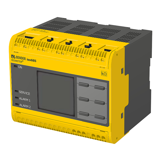
ISOMETER® isoHR685W-x-I-B
Isolationsüberwachungsgerät
Diese Kurzanleitung gilt für die folgenden Gerätevarianten und ersetzt
nicht das Handbuch.
Bestimmungsgemäße Verwendung
Das ISOMETER® isoHR685W-x-I-B überwacht den Isolationswiderstand
von
ungeerdeten
AC/DC-Hauptstromkreisen
Netznennspannungen von AC, AC/DC 0... 1000 V oder DC 0...1300 V.
Die in AC/DC-Systemen vorhandenen gleichstromgespeisten Kompo-
nenten haben keinen Einfluss auf das Ansprechverhalten. Durch die sepa-
rate Versorgungsspannung ist auch die Überwachung eines spannungs-
losen Systems möglich. Die maximal zulässige Netzableitkapazität be-
trägt abhängig vom anwendungsspezifischen Profil bis zu 1000 μF.
Sicherheitshinweise
Gefahr eines elektrischen Schlages!
An den Klemmen liegt eine hohe Spannung an, die bei direkter
Berührung lebensgefährlich ist. Ist das Gerät mit den Klemmen
GEFAHR
L1/+, L2, L3/- an ein betriebsbedingt spannungsführendes IT-
System angeschlossen, dürfen die Klemmen KE und E nicht vom
Schutzleiter (PE) getrennt werden.
Sachschaden durch unsachgemäße Installation!
Die Anlage kann Schaden nehmen, wenn Sie in einem leitend
verbundenen System mehr als ein Isolationsüberwachungs-
VORSICHT
gerät anschließen. Sind mehrere Geräte angeschlossen, fun-
ktioniert das Gerät nicht und meldet keine Isolationsfehler.
Schließen Sie in jedem leitend verbundenen System nur ein
Isolationsüberwachungsgerät an.
Trennung vom IT-System!
Bei Isolations- und Spannungsprüfungen an der Anlage muss
das Isolationsüberwachungsgerät für die Dauer der Prüfung
VORSICHT
vom IT-System getrennt sein. Andernfalls kann das Gerät
Schaden nehmen.
isoHR685W-x-I-B_D00261_03_Q_DEEN/09.2018
Insulation monitoring device
This quickstart guide applies to th following device variants does not re-
place the operating manual.
Intended use
The ISOMETER® isoHR685W-x-I-B monitors the insulation resistance of
(IT-Systemen)
mit
unearthed AC/DC main circuits (IT systems)with mains voltages of AC, AC/
DC 0...1000 V or DC 0...1300 V.
DC components existing in AC/DC systems do not influence the opera-
ting characteristics. A separate supply voltage allows de-energised sys-
tems to be monitored. The maximum permissible system leakage
capacitance is 1000 μF and is dependent on the application-specific pro-
file.
Safety instructions
GEFAHR
VORSICHT
VORSICHT
High risk of electric shock!
The terminals carry high voltage and direct contact with these
terminals will likely result in electrocution. If the terminals L1/+,
L2, L3/- of the device are connected to a live IT system, the termi-
nals E and KE must not be disconnected from the protective
conductor (PE).
Damage to property due to incorrect installation!
There should only be one insulation monitoring device per con-
ductively connected installation. Damage to the installation
may result if several insulation monitoring devices are connec-
ted. In addition, the device will not function and will not report
an insulation fault if more than one insulation monitoring
device is connected.
Disconnect from the IT system!
The insulation monitoring device must be disconnected from
the IT system before insulation or voltage tests at the installa-
tion and must remain so for the duration of the test. Otherwise
the device may be damaged.
1
Werbung
Inhaltsverzeichnis

Verwandte Anleitungen für Bender ISOMETER isoHR685W- I-B Serie


Inhaltszusammenfassung für Bender ISOMETER isoHR685W- I-B Serie
- Seite 1 Kurzanleitung/Quickstart ISOMETER® isoHR685W-x-I-B Isolationsüberwachungsgerät Insulation monitoring device Diese Kurzanleitung gilt für die folgenden Gerätevarianten und ersetzt This quickstart guide applies to th following device variants does not re- nicht das Handbuch. place the operating manual. Bestimmungsgemäße Verwendung Intended use Das ISOMETER® isoHR685W-x-I-B überwacht den Isolationswiderstand The ISOMETER®...
-
Seite 2: Montage
ISOMETER® isoHR685W-x-I-B Montage Installation 20 mm 0 mm 0 mm 20 mm Montage auf Hutschiene DIN rail mounting: Rasten Sie alle 3 mitgelieferten Montageclips (2 separat verpackt) des Ge- Snap all 3 mounting clips delivered with the device (2 of them packed se- räts auf der Hutschiene unten so ein, dass ein sicherer und fester Sitz parately) onto the DIN rail in such a way that a safe and tight fit is ensured. - Seite 3 ISOMETER® isoHR685W-x-I-B Anschlussplan Wiring diagram 3NAC L− > 690 V => F 2A L3/- L3/- A1/+ A2/– L1/+ A1/+ A2/– L1/+ A1/+ A2/– L1/+ L3/- iso685W-x-I-B + AGHxxxx IT-System A1/+ A2/– L1/+ L3/- RS-485 RS-485 AGH xxxx I1 I2 n(IT-System) Deactiv.
- Seite 4 ISOMETER® isoHR685W-x-I-B Systemübersicht: ISOsync zur Überwachung langer paralleler Kabel System overview: ISOsync for monitoring of long parallel cables ISOMETERRs can interfere with each other when used in capacitively cou- Bei dem Einsatz von ISOMETER®n in kapazitiv gekoppelten IT-Systemen pled IT-systems. kann es zu gegenseitiger Beeinflussung der ISOMETER®...
-
Seite 5: Commissioning Of The Device
ISOMETER® isoHR685W-x-I-B Inbetriebnahme des Geräts Commissioning of the device Das Profil „Leistungskreise“ ist für die meisten IT-Systeme The profile "power circuits" is suitable for most IT systems. For a geeignet. Eine Beschreibung der Profile finden Sie im Hand- description of the profiles refer to the manual. buch. -
Seite 6: Alarm Und Seine Wirkung
ISOMETER® isoHR685W-x-I-B Alarm und seine Wirkung Alarm and its effect Ursachen für eine Alarmmeldung Cause of the alarm • Gemessener Isolationswiderstand unterschreitet Ansprechwerte The measured insulation resistance is below the response value • „Alarm 1“ bzw. „Alarm 2“ "Alarm 1" or "Alarm 2" •... -
Seite 7: Technische Daten
ISOMETER® isoHR685W-x-I-B Technische Daten Technical data Isolationskoordination Insulation coordination Bemessungsisolationsspannung (IEC 60664-1) ..................1000 V Rated insulation voltage (IEC 60664-1) ....................1000 V Bemessungs-Stoßspannung (IEC 60664-1) ....................8 kV Rated impulse voltage (IEC 60664-1) ......................8 kV Überspannungskategorie........................III, 1000 V Overvoltage category ..........................III, 1000 V ................................ - Seite 8 Änderungen vorbehalten! Subject to change! © © Bender GmbH & Co. KG Bender GmbH & Co. KG Service Bender GmbH & Co. KG Service hotline: 0700-BenderHelp (Telephone and Fax) Postfach 1161 • 35301 Gruenberg • Germany Carl-Benz-Straße 8 •...