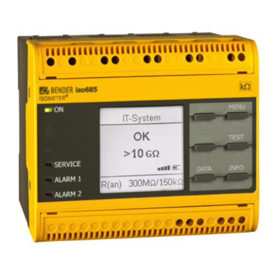
Inhaltszusammenfassung für Bender ISOMETER isoHR685W I-B Serie
- Seite 1 ISOMETER® isoHR685W-x-I-B Isolationsüberwachungsgerät Insulation monitoring device isoHR685W-x-I-B_D00261_05_Q_DEEN/12.2021 Kurzanleitung / Quick-start guide DE/EN...
-
Seite 2: Sicherheitshinweise
ISOMETER® isoHR685W-x-I-B Isolationsüberwachungsgerät Insulation monitoring device Diese Kurzanleitung gilt für die folgenden This quickstart guide applies to th following Gerätevarianten und ersetzt nicht das Hand- device variants does not replace the operating buch. manual. Bestellangaben: Typ / Type Versorgungsspannung Us / Supply voltage Us Art.-Nr. / Art.-No. Handbuch Nr. / Manual No. B91067025W isoHR685W-D-I-B AC 24…240 V via A1/+, A2/- (50…400 Hz) - Seite 3 ISOMETER® isoHR685W-x-I-B Maße Dimensions 108 (4.25) 108 (4.25) 110 (4.33) 110 (4.33) 20 mm 0 mm 0 mm (3.66) (3.66) 20 mm Mounting Montage Ø M4 Anschluss Connection Verdrahten Sie das Gerät gemäß Anschlussplan. Wire up the device according to the wiring diagram Beachten Sie dabei die technischen Daten.
- Seite 4 ISOMETER® isoHR685W-x-I-B Anschlussbild L1/+ L3/- Legende zu den Anschlussbildern Klemme Anschlüsse 3(N)AC A1/+ A2/- ** Stromversorgung, = 24…240V (50…400Hz) L1/+, L2, L3/- Anschlüsse an das zu überwachende Netz L1/+ L3/- AC 0…1000 V, 3AC 0…690 V L1/+ L3/- DC 0…1300 V AC/DC 0…1000 V für UL-Anwendungen IT system 1 IT system 2...
-
Seite 5: Wiring Diagram
ISOMETER® isoHR685W-x-I-B Wiring diagram Legend to terminal diagrams Terminal Connections A1/+ A2/- L1/+ L3/- A1/+ A2/- ** Power supply, = 24…240V (50…400 Hz) A1/+ A2/- L1/+ L3/- KE E L1/+, L2, L3/- Connections to the system to be monitored AC 0…1000 V, 3AC 0…690 V DC 0…1300 V AC/DC 0…1000 V for UL applications KE E... - Seite 6 ISOMETER® isoHR685W-x-I-B ISOsync: Überwachung langer paralleler Kabel ISOsync: Monitoring of long parallel cables In kapazitiv gekoppelten IT-Systemen kann es zu ge- ISOMETER®s can interfere with each other when used genseitiger Beeinflussung der ISOMETER® kommen. in capacitively coupled IT-systems. A1/+ A2/- L1/+ L3/- A1/+...
-
Seite 7: Commissioning Of The Device
ISOMETER® isoHR685W-x-I-B Inbetriebnahme des Geräts Commissioning of the device 1. Prüfen auf korrekten Anschluss des ISOMETER®s an 1. Check that the ISOMETER® is properly connected to das zuüberwachende Netz. the system to be monitored. 2. Versorgungsspannung für ISOMETER® zuschalten 2. Connect the supply voltage to the ISOMETER® 3. -
Seite 8: Automatischer Oder Manueller Test
ISOMETER® isoHR685W-x-I-B Schritte zur Inbetriebnahme Steps for Commision Select Select Select Response value Response value Language Date and time System type pro le for Alarm 1 for Alarm 2 Power circuit Deutsch 17.02.2020... -
Seite 9: Werkseinstellungen
ISOMETER® isoHR685W-x-I-B Werkseinstellungen Factory settings Ansprechwerte Response values Ansprechwert R (Alarm 1) ............100 kΩ Response value R (Alarm 1) ............100 kΩ Ansprechwert R (Alarm 2) ............20 kΩ Response value R (Alarm 2) ............20 kΩ Fehlerspeicher..................aus Fault memory ..................off Ankoppelüberwachung ................ein Coupling monitoring ................on Geräteprofil .............. -
Seite 10: Technische Daten
ISOMETER® isoHR685W-x-I-B Technische Daten Technical data Isolationskoordination (IEC 60664-1/IEC 60664-3) Insulation co-ordination (IEC 60664-1/IEC 60664-3) Bemessungsisolationsspannung (IEC 60664-1) ......1000 V Rated insulation voltage (IEC 60664-1) .........1000 V Bemessungs-Stoßspannung (IEC 60664-1) ........8 kV Rated impulse voltage (IEC 60664-1) ..........8 kV Überspannungskategorie (OVC) ..........III, 1000V Overvoltage category (OVC) ............III, 1000 V ....................II, 1300 V ....................II, 1300 V... - Seite 11 ISOMETER® isoHR685W-x-I-B isoHR685W-x-I-B_D00261_05_Q_DEEN/12.2021...
- Seite 12 Nachdruck und Vervielfältigung Reprinting and duplicating nur mit Genehmigung des Herausgebers. only with permission of the publisher. Bender GmbH & Co. KG Bender GmbH & Co. KG Postfach 1161 • 35301 Grünberg • Deutschland PO Box 1161 • 35301 Grünberg • Germany Londorfer Str.


