Gemü ADA 00010 Betriebsanleitung
Schwenkantrieb

Verwandte Anleitungen für Gemü ADA 00010


Inhaltszusammenfassung für Gemü ADA 00010
- Seite 1 ADA / ASR Schwenkantrieb, fremdgesteuert Quarter turn actuator, pneumatically operated ORIGINAL BETRIEBSANLEITUNG OPERATING INSTRUCTIONS GEMÜ ADA mit Stellungsrückmelder GEMÜ LSF GEMÜ ADA with electrical position indicator GEMÜ LSF ADA / ASR...
-
Seite 2: Inhaltsverzeichnis
Inhaltsverzeichnis Allgemeine Hinweise Allgemeine Hinweise Voraussetzungen für die einwandfreie Allgemeine Funktion des GEMÜ-Antriebs: Sicherheitshinweise Sachgerechter Transport und Lagerung Hinweise für Service- Installation und Inbetriebnahme durch und Bedienpersonal eingewiesenes Fachpersonal Warnhinweise Bedienung gemäß dieser Verwendete Symbole Betriebsanleitung Begriffsbestimmungen Ordnungsgemäße Instandhaltung Vorgesehener Einsatzbereich Korrekte Montage, Bedienung, Wartung Technische Daten oder Reparatur gewährleisten einen... -
Seite 3: Hinweise Für Service- Und Bedienpersonal
Hinweise für Service- Warnhinweise und Bedienpersonal Warnhinweise sind, soweit möglich, nach folgendem Schema gegliedert: Die Betriebsanleitung enthält grundlegende Sicherheitshinweise, die bei SIGNALWORT Inbetriebnahme, Betrieb und Wartung zu Art und Quelle der Gefahr beachten sind. Nichtbeachtung kann zur Mögliche Folgen bei Nichtbeachtung. Folge haben: ®... -
Seite 4: Begriffsbestimmungen
Der Antrieb GEMÜ ADA / ASR steuert Pfeil: Beschreibt Reaktion(en) auf ® Absperrklappen und Kugelhähne indem Tätigkeiten. er durch ein Steuermedium geschlossen oder geöffnet werden kann. Aufzählungszeichen Der Antrieb darf nur gemäß den technischen Daten eingesetzt werden (siehe Kapitel 5 "Technische Begriffsbestimmungen Daten"). - Seite 5 Einfach wirkende Antriebe Doppelt wirkende Antriebe EN ISO 5211 Antriebs- Antriebs- Typenschlüssel Typenschlüssel code code Flanschtyp Nabe SW ADA00010 F03Y S09A BO01AT0 ADA00010 F04Y S09A BO01AZ0 ASR0020U S08 F03F05Y S09A AU02FN0 ADA0020U F03F05Y S09A BU02AN0 F03/F05 ASR0020U S08 F04Y S14A AU02FA0 ADA0020U F04Y S14A BU02AA0...
- Seite 6 Drehmomente für einfach wirkende Antriebe - ASR [Nm] Feder- 3 bar 3,5 bar 4 bar 4,5 bar 5 bar 5,5 bar 6 bar (A) 6,5 bar 7 bar 8 bar moment Feder- 0° 90° 0° 90° 0° 90° 0° 90° 0° 90° 0° 90° 0°...
-
Seite 7: Bestelldaten
Bestelldaten 4 Anschlussgröße Code 1 Typ Code Doppelt wirkend Flanschtyp F03 Einfach wirkend Flanschtyp F03/F05 F03/F05 Flanschtyp F04 Flanschtyp F05 Flanschtyp F05/F07 F05/F07 2 Antriebsgröße Code Flanschtyp F07/F10 F07/F10 (Standarddrehmomente [Nm] bei 6 bar Steuerdruck) Flanschtyp F10 ADA [Nm] ASR [Nm] Flanschtyp F10/F12 F10/F12 Federmoment... -
Seite 8: Herstellerangaben
Herstellerangaben Funktionsbeschreibung Der pneumatische Schwenkantrieb arbeitet Transport nach dem Doppelkolbenprinzip und ist doppelt wirkend (ADA) oder einfach wirkend Antrieb nur auf geeignetem Lademittel (ASR) lieferbar. transportieren, nicht stürzen, vorsichtig Er eignet sich für den Aufbau auf handhaben. Absperrklappen und Kugelhähne mit Verpackungsmaterial entsprechend genormten Schnittstellen gemäß... -
Seite 9: Geräteaufbau
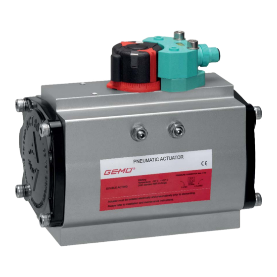
Version F: Nabe mit Stern (Doppelvierkant) / Das Aluminiumgehäuse sowie die Anschluss ISO 5211 / DIN 3337: Gehäusedeckel sind mit einer hochwertigen 4 x 90° = 360° Epoxy Beschichtung versehen (80 - 90 μm). Welle und Schrauben bestehen aus Edelstahl. Hierdurch wird ein sehr øL guter Korrosionsschutz erzielt. -
Seite 10: Pneumatischer Anschluss
(Anschluss 2) öffnet den Antrieb. Entlüften ADA / ∅ □ R ∅ S 5211 ∅ L M x V 5211 x V1 des Antriebs bewirkt das Schließen des 00010 12,1 F03 M5x8 Antriebs durch Federkraft. 00010 12,1 F04 M5x8 0020U 12,5 F03 M5x8 M6x10... -
Seite 11: Einstellung Und Bedienung
Durch den Einsatz einer Hubbegrenzung (optional) können die Endlagen variabel Anschlüsse 2 / 4 siehe Bild auf Seite 10 zwischen 0 ... 90° eingestellt werden (nicht bei Antrieb ADA 00010). Einstellung und Bedienung Einstellung der Endlage 0°: Antrieb in geschlossene Position 12.1... -
Seite 12: Einstellung Der Hubbegrenzung (Optional)
12.3 Einstellung der Antrieb mit drehwinkelabhängiger Hubbegrenzung (optional) Endlageneinstellmöglichkeit (100 %) Länge L [mm] ASR* Spezieller Deckel mit Gewinde Unterlegscheibe (einfach wirkend) 50 % 100 % 00010 0020U 0040U 0080U 0130U 0200U 0300U Einstellschraube Mutter 0500U 0850U Einstellung der Hubbegrenzung: 1200U Antrieb in geöffnete Position bringen. -
Seite 13: Inspektion Und Wartung
Inspektion und Wartung Stellung der Absperrarmatur am Schlitz SZ ablesen und mit optischer VORSICHT Stellungsanzeige vergleichen, ggf. Antrieb in richtige Position drehen. Heiße Anlagenteile! Schlitz SZ quer zur Leitungsrichtung: ® Verbrennungen! ® Antrieb geschlossen. Nur an abgekühlter Anlage Schlitz SZ in Leitungsrichtung: ®... -
Seite 14: Ersatzteile Der Multifunktions- Anzeige (Puck) Wechseln
Antrieb drehen, bis sich Vorgehensweise bei ADA 00010: die Sechskantschrauben / Sechskantmuttern 32 einführen lassen. Sechskantschrauben / Sechskantmuttern 32 mit Unterlegscheiben 31 wieder handfest hineindrehen. Sechskantschrauben / Sechskantmuttern 32 gleichmäßig über Kreuz festziehen: 1. Abdeckkappen 1 nach oben abziehen. Schrauben- / 2. - Seite 15 9. Neuen Puck 5 aufstecken. 10. Neue Federringe 4 aufl egen und mit neuen Zylinderschrauben 3 festschrauben. 2. Puck 2 nach oben abziehen. 3. Skalenring 3 nach oben abziehen. 4. Adapterhülse 4 nach oben abziehen. 11. Abdeckkappe 2 aufstecken und mit passendem Innensechskantschlüssel festschrauben.
-
Seite 16: Demontage
Demontage Hinweise Demontage erfolgt unter den gleichen Hinweis zur Richtlinie Vorsichtsmaßnahmen wie die Montage. 2014/34/EU (ATEX Richtlinie): Antrieb demontieren (siehe Kapitel 10 Ein Beiblatt zur Richtlinie "Mechanischer Anbau"). 2014/34/EU liegt dem Produkt bei, sofern es gemäß ATEX bestellt wurde. Entsorgung Hinweis zur Alle Antriebsteile Mitarbeiterschulung:... -
Seite 17: Fehlersuche / Störungsbehebung
Fehlersuche / Störungsbehebung Fehler Möglicher Grund Fehlerbehebung Betriebsdruck zu hoch Absperrarmatur mit Betriebsdruck laut Datenblatt betreiben Steuerdruck zu niedrig Antrieb mit Steuerdruck laut Datenblatt betreiben (6 - 8 bar) Steuermedium nicht angeschlossen Steuermedium anschließen Antriebsauslegung nicht für Antrieb verwenden, der für die Betriebsbedingungen Betriebsbedingungen geeignet ausgelegt ist Antrieb öffnet /... -
Seite 18: Standardausführung
Standardausführung: Standardausführung: ADA 00010 Pos. Beschreibung Material / Spezifikation Pos. Beschreibung Material / Spezifikation Gehäuse Aluminium Endlageneinstellung ASTM A 105 Kolben Aluminium Federpakete Polyamid PA 6.6 Welle C-Stahl, Nickel beschichtet Einstellschrauben Edelstahl Deckel (End Caps) Aluminium, Epoxy beschichtet Federn DIN 2076 D-5.6 Stützscheibe... -
Seite 19: Konformitätserklärung
Konformitätserklärung ADA / ASR 19 / 40... -
Seite 20: Atex-Bestätigung
ATEX-Bestätigung BESTÄTIGUNG DES EINGANGS DER UNTERLAGEN Nicht-elektrische Geräte zur Verwendung in explosionsgefährdeten Bereichen Richtlinie 94/9/EG Bestätigungsnummer LCIE 05 AR 022 Dossier : 60035219-534543 Anlage oder Schutzsystem : Pneumatische Antriebe ACTREG – Serie ADA, ASR Antragsteller : ACTREG S.A. Adresse : Cantabria, 2 –... -
Seite 38: Declaration Of Conformity
Declaration of Conformity ADA / ASR 38 / 40... -
Seite 39: Atex Confirmation
ATEX confirmation ADA / ASR 39 / 40... - Seite 40 GEMÜ Gebr. Müller Apparatebau GmbH & Co. KG · Fritz-Müller-Str. 6-8 · D-74653 Ingelfi ngen-Criesbach Telefon +49(0)7940/123-0 · Telefax +49(0)7940/123-192 · info@gemue.de · www.gemu-group.com...