Inhaltsverzeichnis
Werbung
Verfügbare Sprachen
Verfügbare Sprachen
General Safety Information
WARNING
• The calipers and rotor will become hot when the brakes are operated, so do not touch them
while riding or immediately after dismounting from the bicycle, otherwise you may get burned.
Check that the brake components have cooled down sufficiently before attempting to adjust
the brakes.
• The required braking distance will be longer during wet weather.
Reduce your speed and apply the brakes early and gently.
• If the road surface is wet, the tires will skid more easily. If the tires skid, you may fall off the
bicycle. To avoid this, reduce your speed and apply the brakes early and gently.
• Always make sure that the front and rear brakes are working correctly before you ride the
bicycle.
• Be careful not to allow any oil or grease to get onto the rotor and brake pads, otherwise the
brakes may not work correctly.
• If any oil or grease do get on the pads, you should replace the pads. If any oil or grease gets
on the rotor, you should clean the rotor. If this is not done, the brakes may not work correctly.
• Use only genuine Shimano mineral oil. If other types of oil are used, it may cause problems
with brake operation, and cause the system to be unuseable.
• Be sure to use only oil from a freshly-opened container, and do not re-use oil which has been
drained from the bleed nipple. Old oil or already-used oil may contain water which could cause
vapor lock in the brake system.
• Be careful not to let water or air bubbles to get into the brake system, otherwise vapor lock
may occur. Be particularly careful when removing the cover of the reservoir tank.
• Vapor lock may occur if the brakes are applied continuously. To relieve this condition,
momentarily release the lever.
Vapor lock is a phenomenon in which the oil inside the brake system becomes heated,
which causes any water or air bubbles inside the brake system to expand. This can then
result in a sudden increase in the brake lever stroke.
• When turning the bicycle upside down or on its side the brake system may have some air
bubbles inside the reservoir tank which are still there when the reservoir tank cover is
replaced, or which accumulate in various parts of the brake system when it is used for long
periods. The M755 disc brake system is not designed to be turned upside down. If the bicycle
is turned upside down or on its side, the air bubbles inside the reservoir tank may move in the
direction of the calipers. If the bicycle is ridden in this condition, there is the danger that the
brakes may not operate and a serious accident could occur.
If the bicycle has been turned upside down or on its side, be sure to operate the brake lever a
few times to check that the brakes operate normally before riding the bicycle. If the brakes do
not operate normally, adjust them by the following procedure.
< If brake operation is sluggish when the lever is depressed >
Gently depress the brake lever several times and wait for the bubbles to return to the
reservoir tank. It is recommended that you then remove the reservoir tank cover and fill
the reservoir tank with brake fluid until no bubbles remain.
If the brakes still operate sluggishly, bleed the air from the brake system.
(Refer to "Adding the brake fluid and bleeding air".)
• If fluid leaks occur, immediately stop using the brakes and carry out the appropriate repairs. If
you continue riding the bicycle while fluid is leaking, there is the danger that the brakes may
suddenly stop working.
• Check that the quick release lever is on the right side (the opposite side to the rotor). If the
quick release lever is on the same side as the rotor, there is the danger that it may interfere
with the rotor, so check that it does not interfere.
• It is important to completely understand the operation of your bicycle's brake system. Improper
use of your bicycle's brake system may result in a loss of control or an accident, which could
lead to severe injury. Because each bicycle may handle differently, be sure to learn the proper
braking technique (including brake lever pressure and bicycle control characteristics) and
operation of your bicycle. This can be done by consulting your professional bicycle dealer and
the bicycle's owners manual, and by practicing your riding and braking technique.
• Obtain, read and carefully service instructions when installing parts. A loose, worn, or
damaged parts may cause injury to the rider.
We strongly recommend that only genuine Shimano replacement parts be used.
• Read these Technical Service Instructions carefully, and keep them in a safe place for later
reference.
CAUTION
• M04 brake pads are designed to reduce the amount of noise which is
generated between the pads and the rotor when the brakes are operated. A
longer running-in period is required for this type of pad compared to M03 pads.
I Handling the mineral oil
• Use safety glasses when handling, and avoid contact with eyes. Contact with eyes may result
in irritation.
• Use gloves when handling. Contact with skin may cause a rash and discomfort.
• Inhalation of oil mist or vapors may cause nausea. Cover nose and mouth with a respirator
type mask and use in a well ventilated area.
• Do not drink. May cause vomiting or diarrhea.
• Keep out of reach of children.
• Do not cut, heat, weld or pressurize the oil container, as this may cause explosion or fire.
I Emergency Care
• In the event of eye contact, flush with fresh water and seek medical assistance immediately.
• In the event of skin contact, wash well with soap and water.
• If mist or vapor is inhaled, go immediately to an area with fresh air. Cover up with a blanket.
Stay warm and stable and seek professional medical advice.
I Disposal of Used Oil
• Follow local county and/or state codes for disposal. Use care when preparing oil for disposal.
I Directions
• Keep the container sealed to prevent foreign objects and moisture from getting inside, and
store it in a cool, dark area away from direct sunlight or heat.
I Burn-in period
• Disc brakes have a burn-in period, and the braking force will gradually increase as the burn-in
period progresses. Make sure that you are aware of any such increases in braking force when
using the brakes during the burn-in period. The same thing will happen when the brake pads or
rotor are replaced.
I When cleaning with a compressor
• If disassembling the caliper body to clean the internal parts using a compressor, note that
moisture from the compressed air may remain on the caliper components. Let the caliper
components dry sufficiently before reassembling the calipers.
Technical Service Instructions
Disc Brake System
( For Cross-Country )
In order to realize the best performance, we recommend that the following combination be
used.
Caliper
BR-M755
Cable Supporter
SM-HANG
Brake Lever
BL-M756
Mineral Oil
SM-DB-OIL
Rotor
SM-RT75
Metal Pads
M03
Brake pad
unit
Hose
SM-BH62
Resin Pads
M04
4
1
Check that the hose is
positioned as shown in
the illustration.
Note
• When the bicycle wheel has been removed, it is recommended that pad
spacers should be installed. The pad spacers will prevent the piston from
coming out if the brake lever is depressed while the wheel is removed.
• If the brake lever is depressed without the pad spacers installed, the pistons will
protrude further than is normal. Use a flat-tipped screwdriver or similar tool to
push back the brake pads, while being careful not to damage the surfaces of
the brake pads. (If the brake pads are not installed, push the pistons straight
back in, while being careful not to damage them.)
If it is difficult to push the brake pads or pistons back, remove the reservoir tank
cover and then try again. (Note that some oil may overflow from the reservoir
tank at this time.)
Adding brake fluid and bleeding air
• Use isopropyl alcohol, soapy water or a dry cloth when carrying out cleaning
and maintenance of the brake system. Do not use commercially-available brake
1.
cleansers or silencing agents, as they can cause damage to parts such as
With the pad spacers still attached to
seals.
the calipers, place the bicycle into a
bicycle stand or similar as shown in
• Do not remove the pistons when disassembling the calipers.
• If the rotor is worn, cracked or warped, it should be replaced.
the illustration so that the reservoir
• Parts are not guaranteed against natural wear or deterioration resulting from
tank is parallel to the ground.
normal use.
• For maximum performance we highly recommend Shimano lubricants and
maintenance products.
Installation
The following tools are needed to assemble this product.
Usage location
Tool
Rotor fixing bolt
Torx wrench #25
Rotor tightening plate
Flat-tipped screwdriver
2.
Set a 8mm socket wrench in place,
attach a bag to the tube, and then
Brake lever fixing bolt
Allen key 5 mm
place the tube onto the bleed nipple
Caliper fixing bolt
Allen key 5 mm
as shown in the illustration.
Adapter (post type) fixing bolt
Allen key 5 mm
Brake pad fixing shaft
Allen key 3 mm
Reservoir tank cover
Phillips screwdriver #1
Cable supporter
Phillips screwdriver #2
Brake hose fixing bolt
Spanner 10 mm
Bleed nipple
Socket wrench 8 mm
3.
Loosen the bleed nipple by 1/8th of a turn to open it, and then pour oil into the
reservoir tank. Gently operate the brake lever while doing this to help prime
I Wheel spoke lacing
the system with the oil.
Check that the spokes have been laced as shown in the illustration.
4.
A radial assembly cannot be used.
When the oil goes into the hose, the oil level in
the reservoir tank will drop, so be sure to
Lace the spokes as shown in Figure 1 below for the left side of the front wheel
continue adding oil to maintain the oil level so
(the side where the roter is installed), and the left and right sides of the rear
that air is not drawn in through the port.
wheel, and as shown in Figure 2 below for the right side of the front wheel.
Rotating
Front left
Rear left Rear right
Front right
direction of
wheel
Fig. 1
Fig. 2
I Installation of the rotor (SM-RT75)
Tightening plate
Fig. 1
Install the rotor and the rotor tightening
Rotor
plate to the hub, and then install and
tighten the bolts as shown in Fig. 1.
Hub
Rotor fixing bolts
(#T25 torx)
While wearing gloves, apply a force to the rotor
to turn it in a clockwise direction as shown in Fig.
Tightening torque:
2. While doing this, tighten the rotor fixing bolts
2 - 4 N·m {18 - 35 in. lbs.}
in the order shown in the illustration.
Use a flat-tipped screwdriver or similar tool to bend the edges of the tightening
plate over the heads of the bolts as shown in Fig. 3.
Fig. 2
Fig. 3
Tightening plate
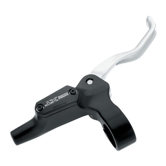
I Installation of the brake lever (BL-M756)
Secure the brake lever as shown in the illustration. (Check that the brake lever
does not interfere with the shifting lever during operation. Refer to the Service
Instructions for the shifting lever also.
Some types might require
the shifting lever to be installed first, due
to the position
of the shifting lever fixing bolts.)
Brake lever Tightening torque:
6 - 8 N·m {53 - 69 in. lbs.}
I Installation of the hose
Install to the brake lever as shown in the illustration. Check that the O-rings are
positioned in the grooves at both the top and bottom of the banjo, and then
secure the banjo to the calipers as shown in the illustration. Make sure that the
O-rings do not protrude from the grooves at this time.
At brake lever end
At caliper end
Hose
Banjo
O-rings
Tightening torque:
5 - 7 N·m {44 - 60 in. lbs.}
The O-ring has grease applied.
5.
With the brake lever depressed, open and close the bleed
nipple in rapid succession (for approximately 0.5 seconds each
time) to release any air bubbles which may be in the calipers.
Repeat this procedure about 2 to 3 times.
Parallel 910°
Then tighten the bleed nipple again.
6.
Fill the reservoir tank with oil and then replace the reservoir tank cover. Fill the reservoir tank to
overflowing with oil while replacing the cover to ensure that no air bubbles remain inside the
Tank should be parallel
reservoir tank. In addition, be careful not to get any oil on parts such as the rotor and brake pads.
to the ground
Reservoir tank
7.
Return the brake lever to its original position.
Hose
Calipers
Note:
Do not use brake fluid fillers, as they can cause small bubbles of air to form, and such
Tube
bubbles can cause severe drops in braking performance.
Bleed nipple
Socket wrench
(8mm)
I Installation of the calipers (BR-M755) and securing the hose.
Remove the pad spacer, and then set the wheel
Bag
which has the rotor onto the frame.
If using post-type caliper mounting bosses, use a
Shimano adapter (F: Y8B298040; R: Y8B298070).
Be sure to use the 170 mm rotor when using the
front adapter.
Start with two 0.5 mm thick shims, and use the 0.2
mm shims for fine tuning. tighten the calipers, and
check that the calipers and the rotor do not
interfere with each other. Next, the caliper fixing
bolts do not contact the rotor. If there is any
interference, or if it looks as though interference
might occur, insert a 2 mm spacer in the position
shown in the illustration.
0.2 mm
If oil periodically comes out from the bleed
nipple, tighten the bleed nipple for a while.
If the brake lever is then operated, air bubbles in
Calipers
the system will rise up through the port into the
reservoir tank. Once the bubbles stop appearing,
depress the brake lever as far as it will go.
The normal condition is for the lever to be stiff at
this point.
Lever operation
Install the accessory caps as shown in the
illustration to prevent the bolts from loosening.
Loose
Slightly stiff
Stiff
If the lever isn't stiff, adjust by the following procedure.
When the lever is depressed once more, bubbles
will rise up and be released into the reservoir
tank. It can be useful to shake the hose gently or
shift the position of the calipers at this time.
Becomes stiff
For C-shaped guides and the
usual type of cable stoppers,
use the special Shimano
cable supporter (sold
separately) to secure as
shown in the illustration.
Operate the brake lever several times and check whether the brakes operate normally or
Tightening torque:
4 - 6 N·m {35 - 53 in. lbs.}
not. Also check that there are no oil leaks visible.
I Brake pad replacement
Tightening torque:
0.3 - 0.5 N·m {2.7 - 4.4 in. lbs.}
If oil adheres to the brake pads after oil is added, or if the brake pads are worn down to a
thickness of 0.5 mm, or if the brake pad presser springs are interfering with the rotor,
replace the brake pads.
1.
2.
3.
4.
Installation of the SHIMANO
adapter and caliper.
< For front >
Front fork
5.
Adapter
Tightening torque:
6 - 8 N·m {53 - 69 in. lbs.}
0.5 mm
< For rear >
Seat stay
6.
7.
Adapter
Shim
(0.5mm, 0.2mm)
I Adjustment when the pistons are not operating correctly
The caliper mechanism includes four pistons. If these pistons do not operate properly or if
they protrude unevenly, or if the brake pads remain in contact with the rotor, adjust the
pistons by the following procedure.
Both long and short types of fixing bolt are
Long bolt
1.
provided. While wearing protective gloves,
apply a force to the calipers to turn it in a
Spacer
counterclockwise direction. While doing
(2mm)
2.
this, tighten the fixing bolts.
Frame
3.
4.
Short bolt
Frame
5.
mounting boss
6.
Rotor
Shim
(0.5mm, 0.2mm)
I Brake fluid replacement
It is recommended that you replace the oil inside the reservoir tank if it becomes severely
Tightening torque:
discolored.
6 - 8 N·m {53 - 69 in. lbs.}
Attach a tube with a bag to the bleed nipple, and then open the bleed nipple and drain out
the oil. You can operate the brake lever at this time to help the oil to drain out. After draining
the fluid, pour in fresh brake fluid while referring to "Adding the brake fluid and bleeding air".
Use only genuine Shimano mineral oil as the brake fluid.
Dispose of the waste oil according to proper country and/or state disposal regulations.
For post type
Caps
Install as shown in
the illustration.
< For front >
Caps
Please note: specifications are subject to change for improvement without notice. (English)
© Mar. 2003 by Shimano Inc. XBC IZM Printed in Japan
< C-shaped guide >
< Usual type of cable stopper >
Tightening torque:
0.3 - 0.5 N·m {2.7 - 4.4 in. lbs.}
Maintenance
Note:
The M755 brake system is designed so that as the brake pads become worn,
the pistons gradually move outward to automatically adjust the clearance between
the rotor and the brake pads. Therefore, you need to push the pistons back to their
original positions when replacing the brake pads.
Brake pads
Remove the wheel from the frame,
and remove the brake pads as shown in the illustration.
Clean the pistons and surrounding area.
Place the bicycle so that the reservoir tank is parallel to
the ground, and then remove the reservoir tank cover.
3 mm Allen key
Push the piston back in as far as it will
go, while being careful not to twist it.
Piston
(Note that some oil may overflow from
the reservoir tank at this time.)
Install the new brake pads, and
then install the pad spacers.
Pad spacer
Tightening torque:
2 - 4 N·m {18 - 35 in. lbs.}
3 mm Allen key
Depress the brake lever several times to check that the operation becomes stiff.
Check that the rotor and the brake pads do not touch each other, and then check the oil
level (adding more oil if required). After doing this, replace the reservoir tank cover.
Remove the wheel and the brake pads.
Clean the pistons and surrounding area, and remove the reservoir tank cover.
Push the piston back in straight, without bending it. Note that some oil may overflow from
the reservoir tank at this time.
Install the brake pads and the pad spacers.
Depress the brake lever as far as it will go, and then operate it several more times so
that the four pistons all move to their initial positions.
Remove the pad spacers, install the wheel, and then check that there is no interference
between rotor and the calipers. If they are touching, adjust using shims.
After checking the oil level, replace the reservoir tank cover.
This service instruction explains how to use and maintain the Shimano bicycle parts
which have been used on your new bicycle.
For any questions regarding your bicycle or other matters which are not related to
Shimano parts, please contact the place of purchase or the bicycle manufacturer.
®
These service instructions are
printed on recycled paper.
One Holland, Irvine, California 92618, U.S.A. Phone: +1-949-951-5003
Industrieweg 24, 8071 CT Nunspeet, The Netherlands Phone: +31-341-272222
3-77 Oimatsu-cho, Sakai, Osaka 590-8577, Japan
Werbung
Inhaltsverzeichnis

Verwandte Anleitungen für Shimano DEORE XT BR-M755


Inhaltszusammenfassung für Shimano DEORE XT BR-M755
- Seite 1 I Brake pad replacement Tank should be parallel • Use only genuine Shimano mineral oil. If other types of oil are used, it may cause problems seals. the calipers, place the bicycle into a reservoir tank.
-
Seite 2: Montage
• Gebruik uitsluitend originele Shimano minerale olie. Als andere soorten olie worden gebruikt, kan dit onderdelen als afdichtingen kunnen veroorzaken. remblokhouder bevestigd in een te staan Let er verder op dat er geen olie op onderdelen zoals de rotor en de remblokken terechtkomt. -
Seite 3: Installation
Sørg desuden for at Reservoiret skal være • Brug kun original Shimano mineralolie. Hvis du bruger andre former for olie, kan der opstå fastgjort til caliperne, skal cyklen pakningerne. - Seite 4 0.2 mm 0.5 mm...
- Seite 5 I Byte av bromsbelägg hamnar på några delar som till exempel bromsskivan och bromsbeläggen. • Använd endast Shimano original mineralolja. Om andra oljetyper används, kan problem ställa cykeln i ett cykelställ eller • Vi lämnar inga garantier mot normalt slitage och försämring av delar orsakat av uppstår med bromsfunktionen och då...
-
Seite 6: Instalación
• Use sólo aceite mineral genuino de Shimano. Si se usan otros tipos de aceites, se podría tener frenos o agentes silenciadores, pues pueden dañar partes como sellos. - Seite 7 Além disso, tenha cuidado para não derramar óleo em peças como o rotor ou as almofadas do • Use apenas óleo mineral Shimano genuíno. Se forem usados outros tipos de óleo, poderá causar • Não retire os pistões quando estiver desmontando os estribos.
- Seite 8 ° 0.2 mm 0.5 mm...
-
Seite 9: Installazione
Prestare inoltre attenzione a non fare colare l'olio su componenti quali il disco e le pastiglie dei • Utilizzare unicamente olio minerale originale Shimano. Utilizzando altri tipi di olio si possono causare • Non rimuovere i pistoni quando si smontano le pinze. -
Seite 10: Einbau
I Ersetzen der Bremsklötze Sind Sie vorsichtig, daß dabei keine Bremsflüssigkeit auf die Bremsscheibe oder die • Verwenden Sie ausschließlich Shimano-Mineralöl. Bei Verwendung von anderen Arten von Öl, • Eine abgenutzte, gerissene oder verbogene Bremsscheibe muss ersetzt werden. usw., wie in der Abbildung gezeigt, Bremsklötze gelangt. -
Seite 11: Entretien
I Remplacement des plaquettes de frein reste plus aucune bulle d'air dans le réservoir. parallèle au sol. • Utiliser exclusivement de l'huile minérale Shimano d'origine. Si l'on utilise d'autres types d'huile, le d'étanchéité. bicyclette sur un support de bicyclette En outre, veiller à ne pas verser d'huile sur les pièces telles que le disque et les plaquettes de fonctionnement du frein risquera d'être faussé...