Baumer POG 11.2 Montage- Und Betriebsanleitung
+ esl
Inhaltsverzeichnis
Montage- und Betriebsanleitung
Installation and operating instructions
POG 11 + ESL
Kombination
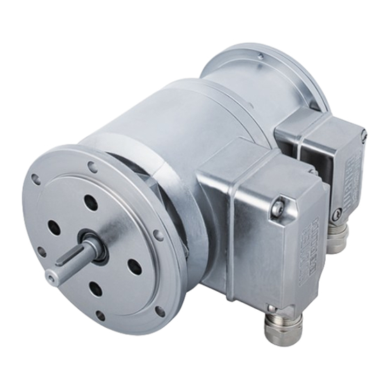
Drehgeber mit integriertem elektronischen Drehzahlschalter
Version B10
Combination
Encoder with integrated electronic speed switch
Version B10
POG 11.2 M + ESL
(Option redundant + EMS)
POG 11.2 + ESL
(Option EMS)
Inhaltsverzeichnis

Verwandte Anleitungen für Baumer POG 11.2


Inhaltszusammenfassung für Baumer POG 11.2
- Seite 1 Montage- und Betriebsanleitung Installation and operating instructions POG 11.2 M + ESL (Option redundant + EMS) POG 11.2 + ESL (Option EMS) POG 11 + ESL Kombination Drehgeber mit integriertem elektronischen Drehzahlschalter Version B10 Combination Encoder with integrated electronic speed switch...
-
Seite 2: Inhaltsverzeichnis
Schritt 1 ................................... Schritt 2 ................................... Schritt 3 ................................... Schritt 4 ................................... Max. zulässige Anbaufehler unter Verwendung der Baumer Hübner Federscheiben-Kupplung K 35 ................Hinweis bei Verwendung einer Klauenkupplung (zum Beispiel „ROTEX®“) ....Anbauhinweis ..............................Abmessung ..................................Elektrischer Anschluss ............................ - Seite 3 Step 2 ..................................Step 3 ..................................Step 4 ..................................Max. permissible mounting tolerance when the Baumer Hübner K 35 spring disk coupling is used ................Note when using a jaw-type coupling (for example “ROTEX®”) ........... Mounting instruction ............................Dimension ..................................
-
Seite 4: Allgemeine Hinweise
Allgemeine Hinweise Allgemeine Hinweise Zeichenerklärung: Gefahr Warnung bei möglichen Gefahren Hinweis zur Beachtung Hinweis zur Gewährleistung eines einwandfreien Betriebes des Produkts Information Empfehlung für die Produkthandhabung Die Kombination POG 11 + ESL ist ein opto-elektronisches Prä zi sionsmessgerät, das mit Sorgfalt nur von technisch qualifiziertem Per sonal gehandhabt werden darf. -
Seite 5: General Notes
General notes General notes Symbol guide: Danger Warnings of possible danger General information for attention Informations to ensure correct product operation Information Recommendation for product handling The combination POG 11 + ESL is an opto electro nic precision measurement device which must be handled with care by skilled personnel only. -
Seite 6: Sicherheitshinweise
Sicherheitshinweise Sicherheitshinweise Verletzungsgefahr durch rotierende Wellen Haare und Kleidungsstücke können von rotierenden Wellen erfasst werden. Vor allen Arbeiten alle Betriebsspannungen ausschalten und Maschinen stillsetzen. • Zerstörungsgefahr durch elektrostatische Aufladung Die elektronischen Bauteile in der Kombination sind empfindlich gegen hohe Spannungen. Steckkontakte und elektronische Komponenten nicht berühren. -
Seite 7: Security Indications
Security indications Security indications Risk of injury due to rotating shafts Hair and clothes may become tangled in rotating shafts. Before all work switch off all operating voltages and ensure machinery is stationary. • Risk of destruction due to electrostatic charge Electronic parts contained in the combination are sensitive to high voltages. -
Seite 8: Vorbereitung
Vorbereitung / Preparation Vorbereitung Preparation Lieferumfang Scope of delivery 11 12 Gehäuse Drehgeber POG 11 Housing encoder POG 11 Gehäuse Drehzahlschalter ESL Housing speed switch ESL EURO-Flansch B10 EURO flange B10 Vollwelle mit Passfeder Solid shaft with key Klemmenkastendeckel POG 11 Terminal box cover POG 11 Kombi-Torx-Schraube M4x32 mm Screw with torx and slotted drive M4x32 mm Kabelverschraubung M20x1,5... -
Seite 9: Zur Montage Erforderlich (Nicht Im Lieferumfang Enthalten)
Vorbereitung / Preparation Zur Montage erforderlich Required for mounting (nicht im Lieferumfang enthalten) (not included in scope of delivery) Anbauvorrichtung, kundenspezifisch Installation fitting, customized Befestigungsschrauben für Anbauvorrichtung Fixing screws for installation fitting ISO 4017, ISO 4017, M6x16 mm M6x16 mm Federscheibenkupplung K 35, Spring disk coupling K 35, als Zubehör erhältlich, siehe Abschnitt 4.5. -
Seite 10: Montage
Montage / Mounting Montage Mounting In den Bildern am Beispiel des POG 11 + ESL Pictures showing type standard POG 11 + ESL as Standard. Gleiche Montageschritte bei allen ande- example. Same mounting steps for all versions. ren Versionen. Schritt 1 Step 1 Zul. -
Seite 11: Schritt 3
Montage / Mounting Schritt 3 Step 3 10 mm Schritt 4 Step 4 2.5 mm Zul. Anzugsmoment Max. tightening torque = 2-3 Nm * Siehe Seite 6 See page 6 MB070.2 - 11055675 Baumer_POG11-ESL_II_DE-EN (16A2) ... -
Seite 12: Max. Zulässige Anbaufehler Unter Verwendung Der Baumer Hübner Federscheiben-Kupplung K 35
K 35 spring disk coupling is used Kombinationen mit Vollwelle sollten Combinations with a solid shaft should be unter Verwendung der Baumer Hübner driven through the Baumer Hübner K 35 Federscheiben-Kupplung K 35 (Zubehör) spring disk coupling (accessory), that can angetrieben werden, die sich ohne axialen be pushed onto the shaft without axial Druck auf die Welle schieben lässt. -
Seite 13: Hinweis Bei Verwendung Einer Klauenkupplung (Zum Beispiel „Rotex®")
Montage / Mounting Hinweis bei Verwendung einer Klauen- Note when using a jaw-type coupling kupplung (zum Beispiel „ROTEX®“) (for example “ROTEX®”) Eine falsche Montage der Klauenkupplung Incorrect mounting of the jaw-type cou- führt zur Beschädigung der Kombination. pling can damage the combination. Mit einem Tiefenmessschieber die Use a depth gauge to find and observe the korrekten Abstände (L, L1), siehe unten,... -
Seite 14: Anbauhinweis
Montage - Abmessung / Mounting - Dimension Anbauhinweis Mounting instruction Wir empfehlen, die Kombination so zu It is recommended to mount the montieren, dass der Kabelanschluss combination with cable connection keinem direkten Wassereintritt aus- facing downward and being not expo- gesetzt ist. -
Seite 15: Elektrischer Anschluss
Elektrischer Anschluss / Electrical connection Elektrischer Anschluss Electrical connection Drehgeber POG 11 Encoder POG 11 6.1.1 Beschreibung der Anschlüsse 6.1.1 Terminal significance Betriebsspannung (für den Drehgeber) +UB; + Voltage supply (for the encoder) Masseanschluss (für die Signale) ; ; GND; 0 V Ground (for the signals) Erdungsanschluss (Gehäuse) Earth ground (chassis) -
Seite 16: Kabelanschluss
Elektrischer Anschluss / Electrical connection Drehgeber POG 11 Encoder POG 11 6.1.3 Kabelanschluss 6.1.3 Cable connection 6.1.3.1 Schritt 1 6.1.3.1 Step 1 TX 20 22 mm 6.1.3.2 Schritt 2 6.1.3.2 Step 2 TX 10 * Siehe Seite 5 See page 5 MB070.2 - 11055675 ... - Seite 17 Elektrischer Anschluss / Electrical connection 6.1.3.3 Schritt 3 und 4 6.1.3.3 Step 3 and 4 ø5-13 mm Ansicht siehe Abschnitt 6.1.4. Kabelschirm Cable shield View see section 6.1.4. * Siehe Seite 6 See page 6 Zur Gewährleistung der angegebenen To ensure the specified protection of Schutzart sind nur geeignete Kabel- the device the correct cable diameter durchmesser zu verwenden.
- Seite 18 Elektrischer Anschluss / Electrical connection Drehgeber POG 11 Encoder POG 11 6.1.3 Kabelanschluss 6.1.3 Cable connection 6.1.3.4 Schritt 5 6.1.3.4 Step 5 Buchse D-SUB TX 10 zum Anschluss an Drehgebergehäuse siehe Abschnitt 6.1.3.5. Connector D-SUB (female) for connecting to encoder housing see section 6.1.3.5.
-
Seite 19: Klemmenbelegung
Elektrischer Anschluss / Electrical connection 6.1.4 Klemmenbelegung 6.1.4 Terminal assignment 6.1.4.1 Standard 6.1.4.1 Standard Max. 1,5 mm Ansicht X Max. AWG 16 Anschlussklemmen, siehe Abschnitt 6.1.3.3. View X Connecting terminal, see section 6.1.3.3. Zwischen besteht keine Verbindung. There is no connection between 6.1.4.2 Mit Option EMS 6.1.4.2... -
Seite 20: Led-Anzeige / Fehlerausgang (Option Ems - Enhanced Monitoring System)
Elektrischer Anschluss / Electrical connection Drehgeber POG 11 Encoder POG 11 6.1.5 LED-Anzeige / Fehlerausgang 6.1.5 LED status / Error output (Option EMS - Enhanced Monitoring (Option EMS - Enhanced Monitoring System) System) Rotblinkend Signalfolge-, Nullimpuls- oder Flash light red Error of signal sequence, zero Impulszahlfehler (Fehlerausgang = pulse or pulses (Error output =... -
Seite 21: Sensorkabel Hek 8 (Zubehör)
Sensorkabel HEK 8 (Zubehör) 6.1.6 Sensor cable HEK 8 (accessory) Es wird empfohlen, das Baumer Hübner Baumer Hübner sensor cable HEK 8 is Sensorkabel HEK 8 zu verwenden oder recommended. As a substitute a shielded ersatzweise ein geschirmtes, paarig ver- twisted pair cable should be used. - Seite 22 Elektrischer Anschluss / Electrical connection Drehzahlschalter ESL Speed switch ESL 6.2.1 Kabelanschluss 6.2.1 Cable connection 6.2.1.2 Schritt 2 6.2.1.2 Step 2 14 * TX 20 Ansicht siehe Abschnitt 6.2.2.1 oder 6.2.3.1. Zul. Anzugsmoment View Max. tightening torque see section 6.2.2.1 or 6.2.3.1. = 2-3 Nm ø5-13 mm Um 180°...
-
Seite 23: Version Esl 90 (1 Internes Relais, 1 Schaltdrehzahl)
Elektrischer Anschluss / Electrical connection 6.2.2 Version ESL 90 6.2.2 Version ESL 90 (1 internes Relais, 1 Schaltdrehzahl) (1 internal relay, 1 switching speed) 6.2.2.1 Anschlussbelegung 6.2.2.1 Terminal assignment Ansicht Y Anschlussklemmen, siehe Abschnitt 6.2.1.2. View Y Connecting terminal, see section 6.2.1.2. ≤6 A / 250 VAC ≤1 A / 48 VDC 6.2.2.2... -
Seite 24: Version Esl 93 (3 Relais-Treiber, 3 Schaltdrehzahlen)
Elektrischer Anschluss / Electrical connection Drehzahlschalter ESL Speed switch ESL 6.2.3 Version ESL 93 6.2.3 Version ESL 93 (3 Relais-Treiber, 3 Schaltdrehzahlen) (3 relay driver, 3 switching speeds) 6.2.3.1 Anschlussbelegung 6.2.3.1 Terminal assignment Kabel: Ansicht Y 5-adrig abgeschirmt, Anschlussklemmen, Länge: ≤200 m bei siehe Abschnitt 6.2.1.2. -
Seite 25: Version Es 93 R Relaismodul (Zubehör)
Elektrischer Anschluss / Electrical connection 6.2.4 Version ES 93 R 6.2.4 Version ES 93 R Relaismodul (Zubehör) Relay modul (accessory) 6.2.4.1 Anschlussbelegung 6.2.4.1 Terminal assignment 3 Kontroll-LED‘s Höhe = 55 mm 3 control LEDs Kunststoffgehäuse für Tragschienenmontage (EN 50022) IP 20 Height = 55 mm 3 Relais/relays Plastic housing for... -
Seite 26: Demontage
Demontage / Dismounting Demontage Dismounting In den Bildern am Beispiel des POG 11 + ESL Pictures showing type standard POG 11 + ESL as Standard. Gleiche Montageschritte bei allen ande- example. Same mounting steps for all versions. ren Versionen. Schritt 1 Step 1 TX 10 TX 20... - Seite 27 Demontage / Dismounting Schritt 2 Step 2 TX 20 22 mm * Siehe Seite 5 oder 6 See page 5 or 6 MB070.2 - 11055675 Baumer_POG11-ESL_II_DE-EN (16A2) ...
- Seite 28 Demontage / Dismounting Schritt 3 Step 3 10 mm 2.5 mm Schritt 4 Step 4 Schritt 5 Step 5 * Siehe Seite 6 2.5 mm See page 6 MB070.2 - 11055675 Baumer_POG11-ESL_II_DE-EN (16A2)
-
Seite 29: Zubehör
Zubehör / Accessories Zubehör Accessories Federscheiben-Kupplung Spring disk coupling • • K 35 K 35 Sensorkabel für Drehgeber Sensor cable for encoders • • HEK 8 HEK 8 Werkzeugset, Tool kit, • • Bestellnummer: 11068265 order number: 11068265 Digital-Konverter: Digital converters: •... -
Seite 30: Technische Daten
Montage / Mounting Technische Daten Technische Daten Technische Daten - elektrisch Störfestigkeit: EN 61000-6-2:2005 • Störaussendung: EN 61000-6-3:2007/A1:2011 • Technische Daten - elektrisch (Drehgeber) Betriebsspannung: 9...30 VDC* (HTL-P, TTL - Version R) • 5 VDC ±5 % (TTL) Betriebsstrom ohne Last: ≤100 mA •... -
Seite 31: Technische Daten - Mechanisch
Technische Daten - mechanisch Baugröße (Flansch): ø115 mm • Wellenart: ø11 mm Vollwelle • Zulässige Wellenbelastung: ≤300 N axial • ≤450 N radial Flansch: EURO-Flansch B10 • Schutzart DIN EN 60529: IP67 • Betriebsdrehmoment typ.: 3 Ncm • Trägheitsmoment Rotor: 220 gcm •... -
Seite 32: Technical Data
Technical data Technical data Technical data - electrical ratings Interference immunity: EN 61000-6-2:2005 • Emitted interference: EN 61000-6-3:2007/A1:2011 • Technical data - electrical ratings (encoder) Voltage supply: 9...30 VDC* (HTL-P, TTL - version R) • 5 VDC ±5 % (TTL) Consumption w/o load: ≤100 mA •... -
Seite 33: Technical Data - Mechanical Design
Technical data - mechanical design Size (flange): ø115 mm • Shaft type: ø11 mm solid shaft • Shaft loading: ≤300 N axial • ≤450 N radial Flange: EURO flange B10 • Protection DIN EN 60529: IP67 • Operating torque typ.: 3 Ncm • Rotor moment of inertia: 220 gcm •... - Seite 34 MB070.2 - 11055675 Baumer_POG11-ESL_II_DE-EN (16A2)
- Seite 35 MB070.2 - 11055675 Baumer_POG11-ESL_II_DE-EN (16A2)
- Seite 36 Baumer Hübner GmbH P.O. Box 12 69 43 · 10609 Berlin, Germany Phone: +49 (0)30/69003-0 · Fax: +49 (0)30/69003-104 info@baumerhuebner.com · www.baumer.com/motion Version: 73864, 73866 MB070.2 - 11055675 Baumer_POG11-ESL_II_DE-EN (16A2 - 23.08.2016)