Baumer POG 90 + ESL Betriebsanleitung

Verwandte Anleitungen für Baumer POG 90 + ESL


Inhaltszusammenfassung für Baumer POG 90 + ESL
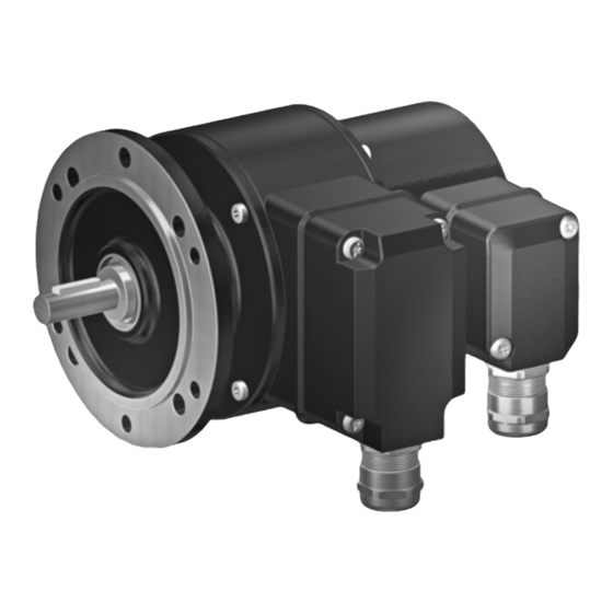
- Seite 1 Montage- und Betriebsanleitung Mounting and operating instructions POG 90 + ESL Kombination Inkrementaler Drehgeber mit integriertem elektronischen Drehzahlschalter Combination Incremental encoder with integrated electronic speed switch...
-
Seite 2: Inhaltsverzeichnis
Schritt 1 ..................................Schritt 2 ..................................Schritt 3 ..................................Schritt 4 ..................................Maximal zulässige Montagefehler unter Verwendung der Baumer Hübner Federscheibenkupplung K 35 ..................Hinweis bei Verwendung einer Klauenkupplung (zum Beispiel „ROTEX®“) ......Montagehinweis ..............................Abmessung ..................................... Elektrischer Anschluss .............................. - Seite 3 Step 2 ..................................... Step 3 ..................................... Step 4 ..................................... Maximum permissible mounting tolerance when the Baumer Hübner K 35 spring disk coupling is used ................. Note when using a jaw-type coupling (for example “ROTEX®”) ........... Mounting instruction ............................. Dimension ....................................
-
Seite 4: Allgemeine Hinweise
Hinweis zur Gewährleistung eines einwandfreien Betriebes des Gerätes Information Empfehlung für die Gerätehandhabung Die Kombination POG 90 + ESL ist ein opto-elektronisches Prä zi sionsmessgerät und ein elektronisch wirkendes Schaltgerät, das mit Sorgfalt nur von technisch qualifiziertem Per sonal gehandhabt werden darf. -
Seite 5: General Notes
Informations to ensure correct device operation Information Recommendation for device handling The combination POG 90 + ESL is an opto electro nic precision measurement device and an electronical operated switching device which must be handled with care by skilled person- nel only. -
Seite 6: Sicherheitshinweise
Sicherheitshinweise Sicherheitshinweise Verletzungsgefahr durch rotierende Wellen Haare und Kleidungsstücke können von rotierenden Wellen erfasst werden. • Vor allen Arbeiten alle Betriebsspannungen ausschalten und Maschinen stillsetzen. Zerstörungsgefahr durch elektrostatische Aufladung Die elektronischen Bauteile im Gerät sind empfindlich gegen hohe Spannungen. • Steckkontakte und elektronische Komponenten nicht berühren. •... -
Seite 7: Security Indications
Security indications Security indications Risk of injury due to rotating shafts Hair and clothes may become tangled in rotating shafts. • Before all work switch off all voltage supplies and ensure machinery is stationary. Risk of destruction due to electrostatic charge Electronic parts contained in the device are sensitive to high voltages. -
Seite 8: Vorbereitung
Vorbereitung / Preparation Vorbereitung Preparation Lieferumfang Scope of delivery Gehäuse POG 90 Housing POG 90 Gehäuse ESL Housing ESL Vollwelle mit Passfeder Solid shaft with key EURO-Flansch B10 EURO flange B10 Klemmenkastendeckel POG 90 Terminal box cover POG 90 Platine mit Anschlussklemmen POG 90, Board with connecting terminal POG 90, siehe Abschnitt 6.1.3.3 und 6.1.4. -
Seite 9: Zur Montage Erforderlich (Nicht Im Lieferumfang Enthalten)
Vorbereitung / Preparation Zur Montage erforderlich Required for mounting (nicht im Lieferumfang enthalten) (not included in scope of delivery) Anbauvorrichtung, kundenspezifisch Installation fitting, customized Befestigungsschrauben M6x16 mm für An- Fixing screws M6x16 mm for installation fit- bauvorrichtung, ISO 4017 ting, ISO 4017 Federscheibenkupplung K 35, Spring disk coupling K 35, als Zubehör erhältlich, siehe Abschnitt 4.5. -
Seite 10: Montage
Montage / Mounting Montage Mounting Schritt 1 Step 1 Zul. Anzugsmoment Max. tightening torque = 100 Ncm 2.5 mm Schritt 2 Step 2 10 mm * Siehe Seite 6 See page 6 Antriebswelle einfetten. Lubricate drive shaft. Die Antriebswelle sollte einen The drive shaft should have as less möglichst kleinen Rundlauffehler runout as possible because this can... -
Seite 11: Schritt 3
Montage / Mounting Schritt 3 Step 3 10 mm Schritt 4 Step 4 2.5 mm Zul. Anzugsmoment Max. tightening torque = 2...3 Nm * Siehe Seite 6 See page 6 MB154.2 - 11067531 Baumer_POG90-ESL_II_DE-EN (18A1) -
Seite 12: Maximal Zulässige Montagefehler Unter Verwendung Der Baumer Hübner Federscheibenkupplung K 35
Montage / Mounting Maximal zulässige Montagefehler Maximum permissible mounting toler- unter Verwendung der Baumer Hübner ance when the Baumer Hübner K 35 Federscheibenkupplung K 35 spring disk coupling is used Geräte mit Vollwelle sollten unter Verwen- Devices with a solid shaft should be dung der Baumer Hübner Federschei-... -
Seite 13: Hinweis Bei Verwendung Einer Klauenkupplung (Zum Beispiel „Rotex®")
Montage / Mounting Hinweis bei Verwendung einer Klauen- Note when using a jaw-type coupling kupplung (zum Beispiel „ROTEX®“) (for example “ROTEX®”) Eine falsche Montage der Klauenkupplung Incorrect mounting of the jaw-type cou- führt zur Beschädigung des Gerätes. pling can damage the device. Mit einem Tiefenmessschieber die Use a depth gauge to find and observe korrekten Abstände (L, L1), siehe unten,... -
Seite 14: Montagehinweis
Montage - Abmessung / Mounting - Dimension Montagehinweis Mounting instruction Wir empfehlen, das Gerät so zu It is recommended to mount the device montieren, dass der Kabelanschluss with cable connection facing down- keinem direkten Wassereintritt ward and being not exposed to water. ausgesetzt ist. Abmessung Dimension (74630) -
Seite 15: Elektrischer Anschluss
Elektrischer Anschluss / Electrical connection Elektrischer Anschluss Electrical connection POG 90 POG 90 6.1.1 Beschreibung der Anschlüsse 6.1.1 Terminal significance Betriebsspannung +UB; + Voltage supply Masseanschluss ; ; GND; 0 V Ground Erdungsanschluss (Gehäuse) Earth ground (chassis) Ausgangssignal Kanal 1 K1; A; A+ Output signal channel 1 Ausgangssignal Kanal 1 invertiert K1;... -
Seite 16: Kabelanschluss
Elektrischer Anschluss / Electrical connection POG 90 POG 90 6.1.3 Kabelanschluss 6.1.3 Cable connection 6.1.3.1 Schritt 1 6.1.3.1 Step 1 11 * TX 20 22 mm 12 * 6.1.3.2 Schritt 2 6.1.3.2 Step 2 TX 10 * Siehe Seite 5 See page 5 MB154.2 - 11067531 Baumer_POG90-ESL_II_DE-EN (18A1) - Seite 17 Elektrischer Anschluss / Electrical connection 6.1.3.3 Schritt 3 und 4 6.1.3.3 Step 3 and 4 12 * ø5...13 mm Ansicht X siehe Abschnitt 6.1.4. Kabelschirm View X Cable shield see section 6.1.4. * Siehe Seite 6 See page 6 Zur Gewährleistung der angegebenen To ensure the specified protection of Schutzart sind nur geeignete Kabel- the device the correct cable diameter...
- Seite 18 Elektrischer Anschluss / Electrical connection POG 90 POG 90 6.1.3 Kabelanschluss 6.1.3 Cable connection 6.1.3.4 Schritt 5 6.1.3.4 Step 5 D-SUB Buchse zum Anschluss an das Gerätegehäuse TX 10 siehe Abschnitt 6.1.3.5. D-SUB connector (female) for connecting to the device housing see section 6.1.3.5. 12 * 22 mm 6.1.3.5...
-
Seite 19: Klemmenbelegung
Sensorkabel HEK 8 (Zubehör) 6.1.5 Sensor cable HEK 8 (accessory) Es wird empfohlen, das Baumer Hübner Baumer Hübner sensor cable HEK 8 is Sensorkabel HEK 8 zu verwenden oder recommended. As a substitute a shielded ersatzweise ein geschirmtes, paarig ver- twisted pair cable should be used. -
Seite 20: Esl
Elektrischer Anschluss / Electrical connection 6.2.1 Kabelanschluss 6.2.1 Cable connection 6.2.1.1 Schritt 1 6.2.1.1 Step 1 TX 20 22 mm 6.2.1.2 Schritt 2 6.2.1.2 Step 2 Um 180° wendbarer Klemmenkasten. Zul. Anzugsmoment Terminal box, turn by 180°. Max. tightening torque = 2...3 Nm Ansicht Y siehe Abschnitt 6.2.2.1 oder 6.2.3.1. -
Seite 21: Esl 90 (1 Internes Relais, 1 Schaltdrehzahl)
Elektrischer Anschluss / Electrical connection 6.2.2 ESL 90 6.2.2 ESL 90 (1 internes Relais, 1 Schaltdrehzahl) (1 internal relay, 1 switching speed) 6.2.2.1 Anschlussbelegung 6.2.2.1 Terminal assignment Ansicht Y Anschlussklemmen, siehe Abschnitt 6.2.1.2. View Y Connecting terminal, see section 6.2.1.2. ≤6 A / 250 VAC ≤1 A / 48 VDC 6.2.2.2 Blockschaltbild... -
Seite 22: Esl 93 (3 Relais-Treiber, 3 Schaltdrehzahlen)
Elektrischer Anschluss / Electrical connection 6.2.3 ESL 93 6.2.3 ESL 93 (3 Relais-Treiber, 3 Schaltdrehzahlen) (3 relay driver, 3 switching speeds) 6.2.3.1 Anschlussbelegung 6.2.3.1 Terminal assignment Kabel: Ansicht Y 5-adrig abgeschirmt, Anschlussklemmen, Länge: ≤200 m bei siehe Abschnitt 6.2.1.2. 1 mm Querschnitt View Y Cable: Connecting terminal, 5 leads shielded,... -
Seite 23: Es 93 R Relaismodul (Zubehör)
Elektrischer Anschluss / Electrical connection 6.2.4 ES 93 R 6.2.4 ES 93 R Relaismodul (Zubehör) Relay modul (accessory) 6.2.4.1 Anschlussbelegung 6.2.4.1 Terminal assignment 3 Kontroll-LED‘s Höhe = 55 mm 3 control LEDs Kunststoffgehäuse für Tragschienenmontage (EN 50022) IP 20 Height = 55 mm 3 Relais/relays Plastic housing for ≤6 A / 250 VAC... -
Seite 24: Demontage
Demontage / Dismounting Demontage Dismounting Schritt 1 Step 1 Elektrische Verbindung trennen. Disconnect electrical connection. TX 10 11 * TX 20 TX 20 22 mm 22 mm * Siehe Seite 5 oder 6 See page 5 or 6 MB154.2 - 11067531 Baumer_POG90-ESL_II_DE-EN (18A1) - Seite 25 Demontage / Dismounting Schritt 2 Step 2 Elektrische Verbindung trennen. Disconnect electrical connection. Schritt 3 Step 3 10 mm 2.5 mm * Siehe Seite 5 oder 6 See page 5 or 6 MB154.2 - 11067531 Baumer_POG90-ESL_II_DE-EN (18A1)
- Seite 26 Demontage / Dismounting Schritt 4 Step 4 Schritt 5 Step 5 2.5 mm * Siehe Seite 6 See page 6 MB154.2 - 11067531 Baumer_POG90-ESL_II_DE-EN (18A1)
-
Seite 27: Zubehör
Zubehör / Accessories Zubehör Accessories • Federscheibenkupplung • Spring disk coupling K 35 K 35 • Sensorkabel für Drehgeber • Sensor cable for encoder HEK 8 HEK 8 • Digital-Konverter • Digital converters HEAG 151 - HEAG 154 HEAG 151 - HEAG 154 •... -
Seite 28: Technische Daten
±4 % (≤1500 U/min) ±2 % (>1500 U/min) • Schalthysterese: ≤30 % der Schaltdrehzahl • Schaltverzögerung: ≤40 ms POG 90 + ESL 90 • Schaltausgänge: 1 Ausgang, drehzahlgesteuert • Ausgangsschaltleistung: ≤6 A / 250 VAC ≤1 A / 48 VDC •... -
Seite 29: Technische Daten - Mechanisch
IEC 60068-2-52 Salzsprühnebel entspricht Umgebungsbedingungen C4 nach ISO 12944-2 • Anschluss: 2x Klemmenkasten • Masse ca.: 2,6 kg POG 90 + ESL 90 • Betriebsdrehzahl: ≤6000 U/min • Schaltdrehzahlbereich (ns): 650...6000 U/min (je nach Bestellung) POG 90 + ESL 90 • Betriebsdrehzahl: ≤5000 U/min... -
Seite 30: Technical Data
Technical data - electrical ratings (speed switch) • Switching accuracy: ±4 % (≤1500 rpm) ±2 % (>1500 rpm) • Switching hysteresis: ≤30 % of switching speed • Switching delay time: ≤40 ms POG 90 + ESL 90 • Switching outputs: 1 output, speed control • Output switching capacity: ≤6 A / 250 VAC ≤1 A / 48 VDC • Minimum switching current: 100 mA POG 90 + ESL 93 •... -
Seite 31: Technical Data - Mechanical Design
Complies to ISO 12944-5 Protective paint systems (C4) • Connection: 2x terminal box • Weight approx.: 2.6 kg POG 90 + ESL 90 • Operating speed: ≤6000 rpm • Range of switching speed (ns): 650...6000 rpm (as ordered) POG 90 + ESL 93 •... - Seite 32 Baumer Hübner GmbH P.O. Box 12 69 43 · 10609 Berlin, Germany Phone: +49 (0)30/69003-0 · Fax: +49 (0)30/69003-104 info@baumerhuebner.com · www.baumer.com/motion Version: 74630 MB154.2 - 11067531 Baumer_POG90-ESL_II_DE-EN (18A1-31.10.2018)