Inhaltsverzeichnis
Werbung
Verfügbare Sprachen
Verfügbare Sprachen
Werbung
Kapitel
Inhaltsverzeichnis

Verwandte Anleitungen für Benning IT 105


Inhaltszusammenfassung für Benning IT 105
- Seite 1 Bedienungsanleitung Operating manual Mehrsprachige Anleitung unter www.benning.de Multilingual manuals at IT 105 HIGH CURRENT 250 V TRIP 500 V AUTO 1 kV x½ RCDt > 440 V Installation Tester...
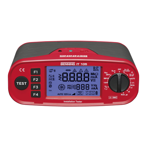
- Seite 2 Gerätefrontseite/ Geräteoberseite Figure 1a: Front tester panel/ device top Bild 1b: Funktionswahlschalter Figure 1b: Function selector switch HIGH CURRENT E F G 250 V TRIP AUTO 500 V x½ 1 kV RCDt > 440 V BENNING IT 105 06/ 2018...
- Seite 3 Bild 1c: Displayanzeige Figure 1c: Digital display Bild 2: -Messung Figure 2: R measurement schwarz black BENNING IT 105 06/ 2018...
- Seite 4 Figure 3: Measurement of Voltage via of 4 mm schwarz measuring leads black Bild 4: Spannungs-, RCD- und -Messung über Prüfkabel mit Schutzkontaktstecker Figure 4: Measurement of voltage, RCD and (Zloop)/Z (Zline) via test cable with shock-proof plug BENNING IT 105 06/ 2018...
- Seite 5 -Messung über 4 mm Messleitung Figure 5: Measurement of voltage, RCD and (Zloop)/Z (Zline) via of 4 mm measuring leads Bild 6: -Messung und PSC-Messung schwarz grün (Phase-Phase) black green Figure 6: Z measurement and PSC measurement (phase-phase) BENNING IT 105 06/ 2018...
- Seite 6 Bild 7: Drehfeldprüfung (Phasenfolge) black green Figure 7: Rotary field (phase sequence) Bild 8: Batterie-/ Sicherungswechsel Figure 8: Battery/fuse replacement FF 1,6A Seriennummer 1000VDC serial number BENNING IT 105 06/ 2018...
-
Seite 7: Inhaltsverzeichnis
Internationale, nationale und gegebenenfalls regionale Vorschriften der Elektrotechnik sind in jedem Fall einzuhalten. Einschlägige Kenntnisse der Elektrotechnik werden vorausgesetzt. Das Installationsprüfgerät BENNING IT 105 ist zur Messung in trockener Umgebung vorgesehen (näheres hierzu im Abschnitt 6: Umgebungsbedingungen). In der Bedienungsanleitung und auf dem BENNING IT 105 werden folgende Symbole verwendet:... -
Seite 8: Sicherheitshinweise
Grenzwert gesunken ist. Trennen Sie das Prüfgerät vom Prüfobjekt und schalten Sie das Prüfgerät aus. Dieses Symbol auf dem BENNING IT 105 bedeutet, dass das BENNING IT 105 konform zu den EU-Richtlinien ist. Dieses Symbol erscheint in der Anzeige für entladene Batterien. Sobald das Batteriesymbol blinkt, tauschen Sie umgehend die Batterien gegen neue Batterien aus. -
Seite 9: Reinigung
Während der Messung keine Metallteile des Prüfobjektes berühren. Das Prüfgerät BENNING IT 105 ist direkt nach beendeter Prüfung von der elektrischen Anlage zu trennen. Verwenden Sie ausschließlich, die im Lieferumfang des BENNING IT 105 enthaltenen Mess- ... -
Seite 10: Gerätebeschreibung
Das BENNING IT 105 benötigt sechs 1,5 V Mignon-Batterien/ Typ AA, IEC LR6 Hinweis auf optionales Zubehör: 40 m Messleitung mit Aufwickler und Handschlaufe, zur Messung von Schutzleiterverbindungen (044039) 4. Gerätebeschreibung siehe Bild 1a: Gerätefrontseite/ Geräteoberseite siehe Bild 1b: Funktionswahlschalter... -
Seite 11: Allgemeine Angaben
Bei Umgebungstemperatur von 0 °C bis 40 °C, nicht kondensierend Lagerungstemperatur: Das BENNING IT 105 kann bei Tem pera turen von - 25 °C bis + 65 °C (Luftfeuchte 0 bis 90 %) gelagert werden. Dabei sind die Batterien aus dem Gerät herauszunehmen. -
Seite 12: Rcd-Prüfung
Benutzen und lagern Sie das BENNING IT 105 nur bei den angegebenen Lager- und Arbeitstemperaturbedingungen, vermeiden Sie dauernde Sonneneinstrahlung. Angaben von Nennspannung und Nennstrom auf den Sicherheitsmessleitungen überprüfen. Starke Störquellen in der Nähe des BENNING IT 105 können zu instabiler Anzeige und zu Messfehlern führen. ... -
Seite 13: Ein-, Ausschalten Des Benning It 105
8.2 Spannung, Frequenz und Drehfeld (Phasenfolge) Mit dem Drehschalter 1 die gewünschte Funktion (V) A wählen. Messleitungen gemäß Bild 3, 4, 5 oder 7 am BENNING IT 105 anschließen und mit dem Prüfobjekt kontaktieren. Die Spannungsmessung startet automatisch, die TEST-Taste 4 oder die Funktionstasten F1 bis F4 3 müssen nicht betätigt werden. -
Seite 14: Isolationswiderstand (Riso )
Widerstandswert an den Messspitzen < 20 kΩ beträgt. Die Funktion bleibt auch nach dem Ausschalten des Prüfgerätes gespeichert. Messleitungen gemäß Bild 2 am BENNING IT 105 anschließen und mit dem Prüfobjekt kontaktieren. Die Durchgangsprüfung startet automatisch, wenn über die Funktionstaste F4 3 die AUTO- Start-Funktion aktiviert wurde. Alternativ betätigen und halten Sie die TEST-Taste 4 , um eine Durchgangsprüfung zu starten. -
Seite 15: Messung Mit Hohem Prüfstrom
IT 105 an Netzspannung angeschlossen wurde. Zum Deaktivieren betätigen Sie erneut die Funktionstaste F4 3 . Messleitungen gemäß Bild 4, 5 oder 6 am BENNING IT 105 anschließen und mit dem Prüfobjekt kon- taktieren. Betätigen Sie die TEST-Taste 4 , um die Messung zu starten. -
Seite 16: Rcd-Prüfung
Die Messung erfordert einen korrekten Anschluss der Netzspannung gemäß Bild 4, 5 oder 6 an das BENNING IT 105. Der Netzspannungsanzeiger muss dauerhaft leuchten: Sollte die Netzspannungsanzeige blinken, drehen Sie den Schutzkontaktstecker des Prüfkabels um 180° oder überprüfen Sie den korrekten Anschluss der Messleitungen. -
Seite 17: Auslösezeit Rcdt (X½, X1, X5)
30 mA ► 100 mA Messleitungen gemäß Bild 4 oder 5 am BENNING IT 105 an schlie ßen und mit dem Prüfobjekt kontak- tieren. Betätigen Sie die TEST-Taste 4 , um die Messung zu starten. Schalten Sie den RCD nach jeder Auslösung wieder ein bis die Prüffolge beendet wurde. -
Seite 18: Auslösestrom Rcd I - Mit Dem Drehschalter 1 Die Gewünschte Funktion Rcd
Messleitungen gemäß Bild 4 oder 5 am BENNING IT 105 an schließen und mit dem Prüfobjekt kontak- tieren. Betätigen Sie die TEST-Taste 4 , um die Messung zu starten. Das Hauptdisplay K zeigt die gemessene Auslösezeit an. -
Seite 19: Instandhaltung
Erkennbaren Folgen von längerer Lagerung unter unzulässigen Bedingungen und Erkennbaren Folgen von außerordentlicher Trans port be an spruchung. In diesen Fällen ist das BENNING IT 105 sofort abzuschalten, von den Prüfstellen zu entfernen und gegen erneute Nutzung zu sichern. 9.2 Reinigung Reinigen Sie das Gehäuse äußerlich mit einem sauberen und trockenen Tuch (Ausnahme spezielle... -
Seite 20: Kalibrierung
Legen Sie das BENNING IT 105 auf die Frontseite und lösen Sie die Schrauben vom Batteriedeckel. Heben Sie den Batteriedeckel vom Unterteil ab. Heben Sie ein Ende der defekten Sicherung seitlich mit einem Schlitzschraubendreher aus dem Sicherungshalter. Entnehmen Sie die defekte Sicherung vollständig aus dem Sicherungshalter. - Seite 21 Operating manual BENNING IT 105 The BENNING IT 105 installation tester is a multifunctional tester for testing electrical installations in com- pliance with IEC 60364-6 (DIN VDE 0100-600) and EN 50110 (DIN VDE 0105-100). The device is intended for the following measurements and tests:...
-
Seite 22: Safety Note
Disconnect the tester from the test object and switch off the tester. This symbol on the BENNING IT 105 means that the BENNING IT 105 complies with the EU directives. -
Seite 23: Scope Of Delivery And Optional Accessories
Parts subject to wear: - The BENNING IT 105 contains a fuse as protection against overload: One fuse, nominal current rating 1.6 A, 1000 V, superfast-acting (FF), breaking capacity ≥ 30 kA, D = 6.3 mm, L = 32 mm (part no. 10194027). - The BENNING IT 105 is powered by six mignon batteries 1.5 V (IEC LR6/ type AA). BENNING IT 105 06/ 2018... -
Seite 24: Description Of Installation Tester
(N-PE) for RCD measurement and loop/line impedance measurement. Indication for correct mains voltage: Note: If the mains voltage indicator flashes, check the measuring leads for correct connection or turn the shock-proof plug of the test cable by 180°: BENNING IT 105 06/ 2018... -
Seite 25: General Information
“Tester is overheated!”; please observe the relevant sections of this operating manual. N Symbol indicating a defective fuse 5. General information The BENNING IT 105 is intended for electrical safety tests in compliance with DIN VDE 0100-600 (IEC 60364-6) and DIN VDE 0105-100 (EN 50110). Appliance dimensions: (length x width x height) = 235 x 132 x 92 mm Appliance weight: 1370 g incl. -
Seite 26: Measuring With The Benning It 105
Check the nominal voltages and nominal current on the safety measuring leads. Strong sources of interference in the vicinity of the BENNING IT 105 might lead to unstable readings and measuring errors. Before starting the installation tester, always check it as well as all measuring leads and ... -
Seite 27: Testing The Battery Condition
8.2 Voltage (V), Frequency (Hz), rotary field (phase sequence) Select the desired function (V) A with the rotary switch 1 . Connect the measuring lead to the BENNING IT 105 as shown in figures 3, 4, 5 or 7 and apply them to the test object. -
Seite 28: Insulating Resistance (Riso )
Connect the measuring leads to the BENNING IT 105 as shown in figure 2 and apply them to the test object. The continuity test is started automatically if the AUTO start function has been enabled via the function key F4 3 . -
Seite 29: Measurement With High Test Current (High Current)
Press the function key F4 3 again to disable the function. Connect the measuring leads to the BENNING IT 105 as shown in figures 4, 5 or 6 and apply them to the test object. -
Seite 30: Rcd Test
8.6 RCD test Measurement requires correct connection of the mains voltage to the BENNING IT 105 as shown in figures 4, 5 or 6. The mains voltage indicator must light permanently: If the mains voltage indicator flashes, turn the shock-proof plug of the test cable by 180° or check the measuring leads for correct connection. -
Seite 31: Tripping Time Rcdt (X½, X1, X5)
30 mA ► 100 mA Connect the measuring leads to the BENNING IT 105 as shown in figures 4 or 5 and apply them to the test object. Press the TEST key 4 to start the measurement. Switch the RCD on again after each tripping until the test sequence is completed. -
Seite 32: Tripping Current Rcdi
Connect the measuring leads to the BENNING IT 105 as shown in figures 4 or 5 and apply them to the test object. Press the TEST key 4 to start the measurement. The measured tripping time is shown on the main display K. -
Seite 33: Maintenance
Electrical danger! Any work required on the BENNING IT 105 when it is under voltage must be done only by a qualified electrician. Special steps must be taken to prevent accidents. Before opening the BENNING IT 105, remove it from all sources of voltage as follows Turn the rotating switch 1 to ”OFF”. -
Seite 34: Spare Parts
Fuse replacement 9.5 Calibration Benning guarantees compliance with the technical and accuracy specifications stated in the operating manual for the first 12 months after the delivery date. To maintain the specified accuracy of the measurement results, the instrument must be recalibrated at regular intervals by our factory service. - Seite 35 Benning Elektrotechnik & Elektronik GmbH & Co. KG Münsterstraße 135 - 137 D - 46397 Bocholt Phone: +49 (0) 2871 - 93 - 0 • Fax: +49 (0) 2871 - 93 - 429 www.benning.de • E-Mail: duspol@benning.de...