Herunterladen Inhalt Inhalt Diese Seite drucken
JVC DT-V9L5 Bedienungsanleitung
Vorschau ausblenden Andere Handbücher für DT-V9L5:
Inhaltsverzeichnis

Werbung

Verfügbare Sprachen
  • DE

Verfügbare Sprachen

  • DEUTSCH, seite 36
DT-V9L5
MULTI FORMAT LCD MONITOR
MONITEUR LCD MULTI-FORMAT
MONITOR LCD MULTIFORMATO
МУЛЬТИФОРМАТНЫЙ ЖК МОНИТОР
BEDIENUNGSANLEITUNG
MANUEL D'INSTRUCTIONS
MANUAL DE INSTRUCCIONES
ИНСТРУКЦИЯ ПО ЭКСПЛУАТАЦИИ
INSTRUCTIONS
ISTRUZIONI
LCT2723-001A
EN
EN
DE
DE
FR
IT IT
ES ES
RU
RU
ZH
(S)

Werbung

Inhaltsverzeichnis
loading

Inhaltszusammenfassung für JVC DT-V9L5

  • Seite 1 DT-V9L5 IT IT MULTI FORMAT LCD MONITOR MULTI FORMAT LCD MONITOR ES ES MONITEUR LCD MULTI-FORMAT MONITOR LCD MULTIFORMATO MONITOR LCD MULTIFORMATO МУЛЬТИФОРМАТНЫЙ ЖК МОНИТОР INSTRUCTIONS BEDIENUNGSANLEITUNG MANUEL D’INSTRUCTIONS ISTRUZIONI MANUAL DE INSTRUCCIONES ИНСТРУКЦИЯ ПО ЭКСПЛУАТАЦИИ LCT2723-001A...
  • Seite 3 MULTI FORMAT LCD MONITOR DT-V9L5 INSTRUCTIONS...
  • Seite 4: Safety Precautions

    Safety Precautions The lightning flash with arrowhead symbol, within an equilateral triangle is CAUTION intended to alert the user to the presence of uninsulated “dangerous voltage” RISK OF ELECTRICAL SHOCK within the product’s enclosure that may DO NOT OPEN be of sufficient magnitude to constitute a risk of electric shock to persons.
  • Seite 5 • Do not attempt to service this product yourself, as opening or The AC power supply is controlled by turning on/off the POWER removing covers may expose you to dangerous voltages and switch on the rear panel. If the product is installed in a place other hazards.
  • Seite 6 (Business users) If you wish to dispose of this product, please visit our web page http:// www.jvc.eu/ to obtain information about the take-back of the product. [Other Countries outside the European Union] If you wish to dispose of this product, please do so in accordance with applicable national legislation or other rules in your country for the treatment of old electrical and electronic equipment.
  • Seite 7: Inhaltsverzeichnis

    Operating Precautions The LCD panel and backlight have life expectancy. Due to the basic characteristics of the LCD panel, an afterimage or uneven display may occur. It is recommended that you change images occasionally, activate the power saving function, or often turn off the power to reduce the load on the LCD panel.
  • Seite 8: Installation

    Installation Caution ● Do not rest your arm on the monitor or lean against the monitor. ● Do not touch the LCD panel when installing the monitor. ● Be sure to install the monitor securely to prevent the monitor from falling over, which may cause damage to the monitor or injury. Adjusting the stand height You can select the stand height according to your preference—higher position or lower position.
  • Seite 9: Tilting The Monitor

    Lower position When you want to lower the position of the monitor. Attachment screws Stand Monitor Tilting the monitor You can tilt the monitor as shown below. About 20° When the monitor is not tilted (0°), the guidelines align as illustrated. 0°...
  • Seite 10: Index Of Parts And Functions

    Index of Parts and Functions Rear panel Carry handle Security slot Use this handle when carrying the monitor. Attach a security wire to this slot. 1 POWER switch Turns AC power on or off. button (☞ q on page 10) to use the monitor after turning on the POWER switch. ●...
  • Seite 11 7 HDMI terminal Input terminal compatible with HDCP for the HDMI signal. (TYPE-A) 8 REMOTE terminal Terminal for controlling the monitor by an external control. (☞ “External Control” on page 23) 9 AUDIO (MONITOR OUT) terminals (pin jack) Output terminals for the analog audio signal. ●...
  • Seite 12: Front Panel

    Index of Parts and Functions (cont.) Front panel Tally lamp This lamp is controlled by the tally function of the MAKE/TRIGGER terminal. • You can select the color of the tally lamp from “Green” or “Red.” You can also select whether the whole lamp is turned on at once, or whether it is turned on one half at a time.
  • Seite 13: Showing Input Signals

    y SCOPE button/lamp Displays/hides the indication of the wave form monitor and vectorscope (☞ “Scope Setting” on page 17). ● Each time you press this button, the window changes in the following order. No display Wave form monitor Histogram Vectorscope u DC lamp When the DC power voltage is being lowered due to the battery consumption, the lamp changes to orange from green.
  • Seite 14: On The Status Display

    Showing Input Signals (cont.) On the Status Display If you press the INPUT SELECT button (☞ 9 on page 10) currently lit, the status of the input signal and setting of MUTING are displayed for about 3 seconds. ● Make the setting to display/hide the status in “Status Display” of the “Information”. (☞ page 20) ●...
  • Seite 15: Menu Transition Diagram

    Menu Transition Diagram Main Menu Picture Function Backlight H Size Aperture H Position Aperture Level V Size Size/Position Adjust V Postion sub menu Gamma reset Aspect Color Temperature sub menu reset Dynamic Auto Aspect Manual Aspect SD4 : 3 Size Signal Setting 16 :...
  • Seite 16: Main Menu

    Menu Configuration (cont.) Main Menu Picture Function Setting for the picture quality. Item To do Setting value Backlight Adjusts the brightness of the display. –20 to +20 Aperture* Activates/deactivates the function at the level set in “Aperture Level”. Off, On Aperture Level* Compensate the frequency response of the luminance signal of the video signal.
  • Seite 17 Signal Setting Settings for input signals. Item To do Setting value Video/Component Select Selects the signal type you want to use for VIDEO/COMPONENT terminals. Video, Component I/P Mode Selects a proper mode corresponding to the input picture. Normal, Cinema Color System Select the color system.
  • Seite 18: Audio Setting

    Menu Configuration (cont.) Audio Setting Settings for EMBEDDED AUDIO signals and audio level meter signal. Item To do Setting value SDI-1 Select Select the input through which audio is output. Off, Auto, Digital, Analog SDI-2 Select Does not output audio. Auto Output digital audio prior to analog audio.
  • Seite 19 Scope Setting* Configure the settings for the wave form monitor and vector scope. Item To do Setting value Gain* Adjust the input gain level. –10 to +10 Size* Set the window size. Normal, Large Position Select the window position. Lower Right, Lower Left Upper Left, Upper Right Transparent Activates/deactivates the function to make the window translucent.
  • Seite 20: Set-Up Menu

    Menu Configuration (cont.) Sync Function Settings for the synchronization with signals. Item To do Setting value No Sync Action Select the screen status when no signal is coming in. Off, Standby, Power Save (power save mode) Gray Back (gray screen) Delay Time Select the period until the screen status changes as selected in “No Sync Action”...
  • Seite 21 Function Key Setting Specify the function assigned to the F1 button. Function1 Specify the function assigned to the F1 button. - - -, Aperture, I/P Mode, * See pages 13 to 22 for details of the functions assigned to Function 1. Frame, Center Marker, Level Meter Display, Gamma, Color...
  • Seite 22: Control Lock

    Menu Configuration (cont.) Remote Setting Settings for the external control. Item To do Setting value Parallel Type Select a control method of the MAKE/TRIGGER terminal. Make, Trigger, Set Pin1 Pin2 ☞ "Display" in "Functions Assign the control functions to the pins of the MAKE/TRIGGER terminal. Pin3 •...
  • Seite 23: All Reset

    Off : Not displayed On : Displayed IMD Protocol Serial communication protocol setting Off, TSL V4.0 Off : Supports JVC protocol TSL V4.0 : Supports TSL UMD Protocol V4.0 Address Address setting 000 to 126 000 to 126 : Set a particular address...
  • Seite 24 Menu Configuration (cont.) ● Setting of “Character Setting” Change the input to one that you want to assign a video source name for. Select “Character Setting”. Ch ar ac te r S e tt in g Press buttons to select the first character. ●...
  • Seite 25: External Control

    External Control About the external control Using the MAKE/TRIGGER system This monitor has three external control terminals. The MAKE/TRIGGER terminal is configured as follows. You can assign ● MAKE/TRIGGER terminal (RJ-45): The following external control a function to each pin terminal in “Remote Setting”. (☞ “Pin1, Pin2, systems are available.
  • Seite 26: Using The Serial Communication

    External Control (cont.) <Functions controlled by the MAKE/TRIGGER system> Display Functions to be controlled Opening Short-circuiting – – – No function — — Tally lamp color selection* Green Tally Color Tally lamp lighting method selection Whole One half at a time Tally Type Light the left half of the tally lamp in red* Tally-L(R)
  • Seite 27 <Command outline> All commands consist of the following segments. Header Monitor ID Function Data Cr (0Dh) On Header “!” : Operation commands from the personal computer, etc. (☞ <Basic command list> below table). “?” : Reference commands from the personal computer, etc. “@”...
  • Seite 28: Troubleshooting

    Troubleshooting Solutions to common problems related to the monitor are described here. If none of the solutions presented here solve the problem, unplug the monitor and consult an authorized dealer or service center. Symptom Probable cause and corrective action Page ●...
  • Seite 29: Self-Check Program

    Self-check program This monitor has a self-check function, which allows it to detect malfunctions and alert you. This makes troubleshooting easier. Whenever a problem occurs, one or some of the INPUT SELECT lamps will flash. If this happens, follow the steps below and contact your dealer to resolve the problem.
  • Seite 30: Specifications

    Specifications General Model name DT-V9L5 Type Multi format LCD monitor Screen size Type 8.2 wide format Aspect ratio 16:10 ☞ “Available signals” on page 30 Compliant video signal format Format HD SDI: SMPTE292M SD SDI: ITU-R BT.656, SMPTE259M EMBEDDED AUDIO 16CH:...
  • Seite 31: Dimensions

    Notice on transportation This monitor is precision equipment and needs dedicated packing material for transportation. Never use any packing material supplied from sources other than JVC or JVC-authorized dealers. ● For easy understanding, pictures and illustrations are shown by being emphasized, omitted or composed, and may be slightly different from actual products.
  • Seite 32: Available Signals

    Specifications (cont.) Available signals The following signals are available for this monitor. Video signals Input terminal Signal format shown in the Signal name status display E.AUDIO * VIDEO analog COMPO. HDMI (☞ page 12)* HD/SD SDI NTSC NTSC √ — —...
  • Seite 33 MEMO...
  • Seite 35 MULTI FORMAT LCD MONITOR DT-V9L5 BEDIENUNGSANLEITUNG...
  • Seite 36 Sicherheitsmaßregeln Das Blitzsymbol in einem gleichseitigen Dreieck weist auf das Vorhandensein von CAUTION nicht isolierten Teilen mit „gefährlicher Spannung“ innerhalb des Gehäuses hin, RISK OF ELECTRICAL SHOCK die bei unvorsichtigen Eingriffen zu DO NOT OPEN elektrischen Schlägen führen können. VORSICHT: Zur Verhinderung von elektrischen Schlägen. Das Ausrufezeichen in einem Keine Abdeckungen (oder Rückplatten) gleichseitigen Dreieck soll den Anwender...
  • Seite 37 • Versuchen Sie nicht, das Produkt selber zu warten, wie etwa Die Netzstromversorgung wird durch Ein-/Ausschalten des durch Öffnen von Abnehmen von Abdeckungen. Im Inneren Netzschalters (POWER) an der Rückseite gesteuert. Wenn das befinden sich Teile mit gefährlicher Hochspannung und andere Produkt an einem Ort aufgestellt ist, wo er sich nicht leicht Gefahrenquellen.
  • Seite 38 Richtlinien. Dieses Gerät ist Sicherheit. für professionelle Videoausrüstungen ausgelegt und kann in den folgenden Umgebungen verwendet werden: Die europäische Vertretung von JVC KENWOOD Corporation ist: • Umgebung mit kontrollierter EMV (zum Beispiel speziell gebaute JVC Technical Services Europe GmbH Postfach 10 05 04 Sende- oder Aufnahmestudios) und ländliche Umgebungen im...
  • Seite 39: Vorsichtsmaßregeln Zum Betrieb

    Vorsichtsmaßregeln zum Betrieb Das LCD-Panel und die Rückbeleuchtung haben eine begrenzte Lebensdauer. Aufgrund der grundlegenden Eigenschaften des LCD- Panels kann ein Nachbild oder eine ungleichmäßige Anzeige auftreten. Wir empfehlen, die Bilder auf dem Display gelegentlich zu wechseln, die Energiesparfunktion zu aktivieren oder regelmäßig die Stromversorgung auszuschalten, um die Belastung des LCD-Panels zu verringern.
  • Seite 40: Aufstellung

    Aufstellung Achtung ● Stützen Sie sich nicht mit dem Arm auf dem Monitor ab oder lehnen sich dagegen. ● Berühren Sie nicht das LCD-Panel bei der Aufstellung des Monitors. ● Stellen Sie sicher, dass der Monitor sicher eingebaut ist, um Herunterfallen zu vermeiden, wodurch der Monitor beschädigt werden oder Verletzungen verursacht werden können.
  • Seite 41: Neigen Des Monitors

    Niedrigere Position Wenn Sie die Position des Monitors senken wollen. Befestigungsschrauben Ständer Monitor Neigen des Monitors Sie können den Monitor wie folgt neigen. Wenn der Monitor nicht geneigt Etwa 20° ist (0°), sind die Führungslinien ausgerichtet, wie gezeigt. 0° Führungslinien Etwa 10°...
  • Seite 42: Index Der Teile Und Funktionen

    Index der Teile und Funktionen Rückseite Tragegriff Sicherheitsschlitz Verwenden Sie diesen Griff beim Tragen des Monitors hoch. Bringen Sie einen Sicherungsdraht an diesem Schlitz an. 1 Netzschalter Schaltet die Netzstromversorgung ein oder aus. (☞ q auf Seite 10) drücken, um den Monitor nach dem Einschalten des Netzschalters zu verwenden. ●...
  • Seite 43 7 HDMI-Klemme Der Eingangsklemmen ist für das HDMI-Signal mit HDCP kompatibel. (TYPE-A) 8 REMOTE-Klemme Klemme für das Steuern des Monitors mithilfe einer externen Steuerung. (☞ „Externe Steuerung“ auf Seite 23) 9 AUDIO (MONITOR OUT)-Klemmen (Klinkenbuchse) Ausgangsklemmen für das analoge Audiosignal. ●...
  • Seite 44: Vorderseite

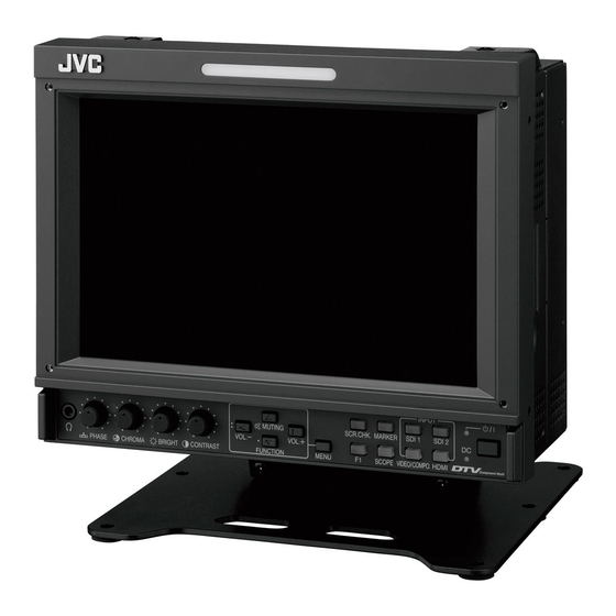
    Index der Teile und Funktionen (Forts.) Vorderseite Signallampe Diese Lampe wird von der Signallampefunktion der MAKE/TRIGGER- Klemme gesteuert. • Sie können die Farbe der Signallampe zwischen „Grün“ und „Rot“ auswählen. Sie können auch auswählen, ob die ganze Lampe auf einmal eingeschaltet wird, oder ab sie jeweils zur Hälfte eingeschaltet wird.
  • Seite 45: Anzeige Von Eingangssignalen

    y SCOPE-Taste/Lampe Zeigt/versteckt die Anzeige des Wellenform-Monitors und Vektorgraphen (☞ „Skope Einstellungen“ auf Seite 17). ● Bei jedem Tastendruck wechselt das Anzeigefenster wie folgt. Keine Anzeige Wellenform-Monitor Histogram Vektorskop u DC-Lampe Wenn die anliegende Gleichspannung aufgrund des Batterieermüdung sinkt, wechselt die Lampe von Grün auf Orange um. Wenn die Spannung unter einen bestimmten Pegel absinkt, schaltet der Monitor automatisch aus, und die Lampe wechselt auf Rot um.
  • Seite 46: Anzeige Des Aktuellen Status

    Anzeige von Eingangssignalen (Forts.) Anzeige des aktuellen Status Wenn Sie die INPUT SELECT-Taste (☞ 9 auf Seite 10) die momentan leuchtet drücken, werden der Status des Eingangssignals und die Einstellung für MUTING etwa 3 Sekunden lang angezeigt. ● Wählen Sie die Einstellung zum Anzeigen/Verstecken des Status in „Status Anzeige“ unter „Informationsanzeige“. (☞ Seite 20) ●...
  • Seite 47: Menü-Transitionsdiagramm

    Menü-Transitionsdiagramm Hauptmenü Bildfunktionen Hintergrundbeleuchtung H Größe Aperatur Bildlage Horizontal Aperaturpegel V Größe Größe und Bildlage Bildlage Vertikal Einblendung unterer Bildrand Gamma zurücksetzen Format Farbtemperatur Einblendung unterer Bildrand zurücksetzen Dynamisch Auto-Aspekt Aspekt manuell SD 4:3 Größe Signal Einstellungen 16:9 Größe 1 : 1 Video/Komponente Auswahl Marker I/P Modus...
  • Seite 48: Hauptmenü

    Menükonfiguration (Forts.) Hauptmenü Bildfunktionen Einstellung der Bildqualität. Gegenstand Einstellwert Hintergrundbeleuchtung Passt die Helligkeit der Anzeige ein. –20 bis +20 Aperatur* Aktiviert/deaktiviert die Funktion auf dem in „Aperaturpegel“ eingestellten Pegel. Aus, Ein Aperatur Level* Ausgleichen den Frequenzgang des Luminanzsignals eines Videosignals. 01 bis 10 Passt die Klarheit der Umrisse des Chrominanzsignals an.
  • Seite 49: Signaleinstellungen

    Signal Einstellungen Einstellungen für Eingangssignale. Gegenstand Einstellwert Video/Komponente Wählt den Signaltyp zur Verwendung für VIDEO/COMPONENT-Klemmen. Video, Komponente Auswahl I/P Modus Wählt einen geeigneten Modus entsprechend dem Eingangsbild. Normal, Kino Farbsystem Auswählen das Farbsystem. Auto, NTSC, PAL, SECAM, NTSC4.43, PAL-M, PAL-N, •...
  • Seite 50: Audio-Einstellungen

    Menükonfiguration (Forts.) Audio-Einstellungen Einstellungen für EMBEDDED AUDIO-Signale und das Audio-Pegelmessersignal. Gegenstand Einstellwert SDI-1 ausgewählt Wählen Sie den Eingang, über den der Ton ausgegeben wird. Aus, Auto, Digital, Analog SDI-2 ausgewählt Gibt kein Audio aus. Auto Gibt digitales Audio vor dem analogen Audio aus. Digital Geben Sie Audio von der SDI-Klemme aus.
  • Seite 51: Skope Einstellungen

    Skope Einstellungen* Konfigurieren Sie die Einstellungen für den Wellenform-Monitor und Vektorskop. Gegenstand Einstellwert Verstärkung* Stellen Sie den Eingang-Gain-Pegel ein. -10 bis +10 Größe* Stellen Sie die Fenstergröße ein. Normal, Groß Position Wählen Sie die Fensterposition. Unten Rechts, Unten Links Oben Links, Oben Rechts Transparent Aktiviert/deaktiviert die Funktion, um das Fenster durchscheinend zu machen.
  • Seite 52: Keine Bedienung

    Menükonfiguration (Forts.) Synchronisations-Modus Einstellungen für die Synchronisation mit Signalen. Gegenstand Einstellwert Ohne Synch.Impuls Wählen des Bildschirmstatus, wenn kein Signal anliegt. Aus, Bereitschaft, Energiesparen (Energiesparmodus) Hintergr. Grau (grauer Bildschirm) Verzögerungszeit Wählen den Zeitraum, bevor der Bildschirmstatus nach dem Stoppen anliegender Signale 30s., 5min., 15min.
  • Seite 53 Funktionstasten-Belegung Legen Sie die der Taste F1 zugewiesene Funktion fest. Funktion 1 Legen Sie die der Taste F1 zugewiesene Funktion fest. - - -, Aperatur, I/P * Siehe Seite 13 bis 22 für Einzelheiten über die zu Funktion 1 zugewiesenen Modus, Funktionen.
  • Seite 54: Fernsteuerungsart

    Menükonfiguration (Forts.) Fernsteuerungsart Einstellungen der externen Steuerung. Gegenstand Einstellwert Parallele-Art Wählen Sie eine Steuerungsmethode des MAKE/TRIGGER-Anschlusses. Make, Trigger, Set Pin1 „Anzeige“ unter „Vom Pin2 Zuweisen die Steuerfunktionen zu den Pins der MAKE/TRIGGER-Klemme. MAKE/TRIGGER-System Pin3 • Weisen Sie eine Funktion zu jedem Anschluss-Pin durch Wählen von „Set“ in „Parallele- gesteuerte Funktionen“...
  • Seite 55: Alles Zurücksetzen

    Aus : Nicht angezeigt Ein : Angezeigt IMD Protokoll Einstellung des seriellen Kommunikationsprotokolls Aus, TSL V4.0 Aus : Unterstützt JVC-Protokoll TSL V4.0 : Unterstützt TSL UMD-Protokoll V4.0 Adresse Adresseinstellung 000 bis 126 000 bis 126 : Stellt eine bestimmte Adresse ein IMD Grösse...
  • Seite 56: Verwendung Von Bildschirmschoner

    Menükonfiguration (Forts.) ● Einstellung von „Ziffern - Einstellungen“ Ändern Sie den Eingang zu einem, zu dem Sie einen Videoquellenname zuweisen wollen. Wählen Sie „Ziffern - Einstellungen“. Z i ff e r n - E i n s t e l l u n g e n Drücken Sie die Tasten zur Wahl des ersten Zeichens.
  • Seite 57: Externe Steuerung

    Externe Steuerung Über die externe Steuerung Verwendung des MAKE/TRIGGER- Systems Der Monitor hat drei externe Steuerklemmen. ● MAKE/TRIGGER-Klemme (RJ-45): Die folgenden externen Der MAKE/TRIGGER-Klemme ist wie folgt konfiguriert. Sie können Steuersysteme stehen zur Verfügung. eine Funktion zu jeder Pin-Klemme in „Fernsteuerungsart“ zuweisen. (1) MAKE (Kontakt-Herstellen)-System: (☞...
  • Seite 58: Verwendung Serieller Kommunikation

    Externe Steuerung (Forts.) <Vom MAKE/TRIGGER-System gesteuerte Funktionen> Anzeige Zu steuernde Funktionen Öffnen Kurzschließen – – – Keine Funktion — — Auswahl der Tally-Lampenfarbe* Grün Tally Farbe Auswahl der Tally-Lampen-Beleuchtungsmethode Ganz Nur jeweils die Hälfte Tally Type Die linke Hälfte der Tally-Lampe leuchtet rot* Tally-L(R) Die rechte Hälfte der Tally-Lampe leuchtet grün* Tally-R(G)
  • Seite 59 <Befehlsumriss> Alle Befehle bestehen aus den folgenden Segmenten. Kopfzeile Monitor-ID Funktion Daten Cr (0Dh) Über Header „!“ : Steuerbefehle vom PC usw. Einzelheiten (☞ <Grundlegende Befehlsliste> siehe Tabelle unten). „?“ : Bezugsbefehle vom PC usw. „@“ : Statusrückgaben vom Monitor Zum Starten der Kommunikation senden Sie den Verbindungsbefehl von dem PC usw.
  • Seite 60: Störungssuche

    Störungssuche Lösungen für übliche Probleme beim Monitor werden hier beschrieben. Wenn keine der hier vorgeschlagenen Lösungen das Problem behebt, trennen Sie den Monitor vom Netz und wenden sich an Ihren Fachhändler oder eine Kundendienststelle. Symptom Mögliche Ursache und Abhilfe Seite ●...
  • Seite 61: Selbstdiagnoseprogramm

    Selbstdiagnoseprogramm Dieser Monitor arbeitet mit einer Selbstdiagnosefunktion, die Betriebsstörungen identifiziert und anzeigt. Dies macht die Fehlerbehebung einfacher. Wenn immer ein Problem auftritt, blinken eine oder mehrere der INPUT SELECT-Lämpchen. Wenn dies eintritt, befolgen Sie die Schritte weiter unten und wenden Sie sich zur Problemlösung an Ihren Fachhändler. INPUT SCOPE HDMI...
  • Seite 62: Technische Daten

    Technische Daten Allgemeines Modellbezeichnung DT-V9L5 Multiformat LCD-Monitor Bildschirmgröße Typ 8,2 Breitformat Seitenverhältnis 16:10 ☞ “Verfügbare Signale“ auf Seite 30 Konformes Videosignalformat Format HD SDI: SMPTE292M SD SDI: ITU-R BT.656, SMPTE259M EMBEDDED AUDIO 16CH: SMPTE299M, SMPTE272M Audioausgang Interner Lautsprecher: 1,0 W Betriebsbedingungen Betriebstemperatur: 5°C –...
  • Seite 63: Abmessungen

    Hinweis zum Transport Dieser Monitor ist ein Präzisionsgerät und benötigt spezielles Verpackungsmaterial zum Transport. Verwenden Sie niemals Verpackungsmaterial von anderen Quellen als JVC oder JVC-Fachhändlern. ● Zum leichteren Verständnis wurden Bilder und Zeichnungen zur Hervorhebung von Erklärungen bearbeitet und können sich deshalb leicht von den tatsächlichen Produkten unterscheiden.
  • Seite 64: Verfügbare Signale

    Technische Daten (Forts.) Verfügbare Signale Die folgenden Signale stehen für diesen Monitor zur Verfügung. Videosignale Eingangsbuchse In der Statusanzeige gezeigtes Signalbezeichnung Signalformat E.AUDIO * VIDEO Analog COMPO. HDMI (☞ Seite 12)* HD/SD SDI NTSC NTSC √ — — — NTSC 4.43 N 4.43 √...
  • Seite 65 NOTIZEN...
  • Seite 67 MONITEUR LCD MULTI-FORMAT DT-V9L5 MANUEL D’INSTRUCTIONS...
  • Seite 68: Précautions De Sécurité

    Précautions de sécurité Le symbole en forme d’éclair avec des tête de flèche dans un triangle équilatéral CAUTION a pour but d’attirer l’attention de l’utilisateur sur la présence d’une “tension RISK OF ELECTRICAL SHOCK dangereuse” non isolée à l’intérieur du DO NOT OPEN boîtier de l’appareil, qui peut être d’une amplitude suffisante pour constituer un...
  • Seite 69 • N’essayez pas de réparer vous même cet appareil, car ouvrir L’alimentation secteur est commandée par la mise sous/hors ou retirer des couvercles vous exposerait à des tensions tension au niveau de l’interrupteur POWER sur le panneau dangereuses ou d’autres dangers. Confier toutes les réparations arrière.
  • Seite 70 Ce matériel électrique. est conçu pour des applications vidéo professionnelles et peut être utilisé dans les milieux suivants: Le représentant européen de JVC KENWOOD Corporation est: • Milieux contrôlés EMC (par exemple studio d’enregistrement ou JVC Technical Services Europe GmbH Postfach 10 05 04 conçu pour la diffusion), et en extérieur (loin des lignes de chemins...
  • Seite 71: Précautions De Fonctionnement

    Précautions de fonctionnement Le panneau LCD et le rétroéclairage ont une durée de vie. Les caractéristiques de base du panneau LCD pourraient produire une image consécutive ou une anomalie d’affichage. Il est conseillé de changer les images régulièrement, d’activer la touche de sauvegarde d’énergie, ou d’éteindre le matériel régulièrement pour diminuer la charge sur le panneau LCD.
  • Seite 72: Installation

    Installation Précaution ● N’appuyez pas votre bras sur le moniteur ni ne vous appuyez à lui. ● Ne touchez pas le panneau à cristaux liquides lors de l’installation du moniteur. ● Assurez-vous d’installer le moniteur de façon sûr pour éviter qu’il tombe et qu’il soit endommagé ou cause des blessures. Ajustage de la hauteur du socle Vous pouvez choisir la hauteur du socle en fonction de vos préférences—position haute ou position basse.
  • Seite 73: Inclinaison Du Moniteur

    Position basse Quand vous souhaitez baisser la position du moniteur. Vis de fixation FR FR Socle Moniteur Inclinaison du moniteur Vous pouvez incliner le moniteur de la façon suivante. Quand le moniteur n’est pas Environ 20° incliné (0°), les lignes guides sont alignées comme montré.
  • Seite 74: Liste Des Pièces Et Des Fonctions

    Liste des pièces et des fonctions Panneau arrière Poignée de transport Verrou de sécurité Utilisez cette poignée lors du transport du moniteur. Fixez un fil de sécurité à cette fente. 1 Interrupteur d’alimentation (POWER) Met l’alimentation secteur en ou hors service. (☞...
  • Seite 75 7 Prise HDMI Prise d’entrée compatible avec HDCP pour le signal HDMI. (TYPE-A) 8 Prise REMOTE Prise pour commander le moniteur à partir d’une commande externe. (☞ “Commande externe” à la page 23) 9 Prises AUDIO (MONITOR OUT) (prise cinch) Prises de sortie pour le signal audio analogique.
  • Seite 76: Panneau Avant

    Liste des pièces et des fonctions (suite) Panneau avant Témoin de signalisation (Tally) Ce témoin est commandé par la fonction de signalisation de la prise MAKE/TRIGGER. • Vous pouvez choisir la couleur du témoin de signalisation “Vert” ou “Rouge”. Vous pouvez aussi sélectionner si tout le témoin s’allume en une fois, ou s’il s’allume une moitié...
  • Seite 77: Affichage Des Signaux D'entrée

    y Touche/témoin SCOPE Affiche/cache l’indication du moniteur de forme d’onde et de l’oscilloscope vectoriel (☞ “Réglage scope” à la page 17). ● Chaque fois que vous appuyez sur cette touche, la fenêtre change de la façon suivante. Moniteur de forme d’onde Pas d’affichage Histogram Oscilloscope vectoriel...
  • Seite 78: À Propos De L'affichage D'état

    Affichage des signaux d’entrée (suite) À propos de l’affichage d’état Si vous appuyez sur la touche INPUT SELECT (☞ 9 à la page 10) actuellement allumée, l’état du signal d’entrée et le réglage de MUTING sont affichés pendant environ 3 secondes. ●...
  • Seite 79: Menu Diagramme De Transition

    Menu Diagramme de transition Menu Principal Fonction Image Rétro-éclairage Taille H Contour Position Horizontale Niveau de Contour Taille V Réglage Taille/Position Position Vertical sous-menu Gamma réinitialisation Aspect Température de couleur sous-menu réinitialisation Dynamique Aspect Auto Aspect Manuel FR FR Taille Standard 4:3 Paramètres Signal Taille 16:9 1 :...
  • Seite 80: Menu Principal

    Configuration des menus (suite) Menu Principal Fonction Image Réglage pour la qualité de l’image. Elément Pour Valeur de réglage Rétro-éclairage Ajuste la luminosité de l’affichage. –20 à +20 Contour * Met en/hors service la fonction au niveau réglé dans “Niveau de Contour”. Arrêt, Marche Niveau de Contour * Compenser la réponse en fréquence du signal de luminance du signal vidéo.
  • Seite 81 Paramètres Signal Réglages pour les signaux d’entrée. Elément Pour Valeur de réglage selection Vidéo/Composantes Choisit le type de signal que vous souhaitez utiliser pour les prises VIDEO/COMPONENT. Vidéo, Composantes Mode I/P Choisit un mode correct correspondant à l’image entrée. Normale, Cinéma Système Couleur Choisit le standard de couleur.
  • Seite 82: Paramètres Audio

    Configuration des menus (suite) Paramètres Audio Réglages pour les signaux EMBEDDED AUDIO et pour les signal d’affichage du niveau audio. Elément Pour Valeur de réglage Sélection audio SDI-1 Sélectionnez l’entrée par laquelle le son est sorti. Arrêt, Auto, Numérique, Sélection audio SDI-2 Analogique Arrêt Le son n’est pas sorti.
  • Seite 83 Réglage scope* Configurer les paramètres du moniteur de forme d’onde et de l’oscilloscope vectoriel. Elément Pour Valeur de réglage Gain* Régler le niveau de l’amplificateur d’entrée. –10 à +10 Taille* Régler la taille de la fenêtre. Normale, Grand Position Sélectionner la position de la fenêtre. Inf.Droit, Inf.Gauche Sup.Gauche, Sup.Droit Transparence...
  • Seite 84: Menu De Paramétrage

    Configuration des menus (suite) Parametres Sync. Réglages de la synchronisation avec les signaux. Elément Pour Valeur de réglage Abscence Sync. Choisir l’état de l’écran quand aucun signal n’est entré. (mode Arrêt, En veille, Energie Eco. d’économie d’énergie) Fond gris (écran gris) Temporisation Choisir la période avant que l’écran ne change comme choisi dans “Abscence Sync.”...
  • Seite 85 Réglage des touches de Spécifiez la fonction affectée à la touche F1. fonction Fonction 1 Spécifiez la fonction affectée à la touche F1. - - -, Contour, * Reportez-vous aux pages 13 à 22 pour les détails sur les fonctions affectées à Fonction 1. Mode I/P, Image, Marqueur Central, Affichage vumètres,...
  • Seite 86 Configuration des menus (suite) Paramètre Télécommande Réglages de la commande externe. Elément Pour Valeur de réglage Type Parallèle Choisir une méthode de commande pour la prise MAKE/TRIGGER. Make, Trigger, Set Pin1 Pin2 ☞ “Display” dans “Fonctions Affecter les fonctions de commande aux broches de la prise MAKE/TRIGGER. Pin3 •...
  • Seite 87 Marche : Displayed Protocole IMD Réglage du protocole de communication série Arrêt, TSL V4.0 Off : Prend en charge le protocole JVC TSL V4.0 : Prend en charge le protocole TSL UMD V4.0 Adresse Réglage de l’adresse 000 à 126 000 à...
  • Seite 88 Configuration des menus (suite) ● Réglage de “Paramètres Caractères” Changez l’entrée à laquelle vous souhaitez affecter un nom de source vidéo. Choisissez “Paramètres Caractères”. P a r a m è t r e s C a r a c t è r e s Appuyez sur les touches pour choisir le premier caractère.
  • Seite 89: Commande Externe

    Commande externe À propos de la commande Utilisation du système MAKE/ externe TRIGGER Ce moniteur a trois prises de commande externe. La prise MAKE/TRIGGER est configurée comme suit. Vous ● Prise MAKE/TRIGGER (RJ-45): Les systèmes de commande externe pouvez affecter des fonctions à chaque broche dans “Paramètre suivants sont disponibles.
  • Seite 90: Utilisation De La Communication Série

    Commande externe (suite) <Fonctions commandées par le système MAKE/TRIGGER> Display Fonctions à commander Ouverture Court-circuit – – – Pas de fonction — — Sélection de la couleur du témoin de signalisation* Vert Rouge Couleur Tally Sélection de la méthode d’éclairage du témoin de signalisation Entièrement Une moitié...
  • Seite 91 <Présentation des commandes> Toutes les commandes sont constituées des segments suivants. Numéro d’identification du Entête Fonction Données Cr (0Dh) moniteur À propos de l’entête “!” : Commandes de fonctionnement à partir de l’ordinateur personnel, etc. (☞ <Basic command list> au tableau ci-dessous). “?”...
  • Seite 92: Dépannage

    Dépannage Des solutions aux problèmes usuels relatifs à votre moniteur sont données ici. Si aucune des solutions données ici ne résout votre problème, débranchez le moniteur et consultez un revendeur autorisé ou un centre de service après-vente. Symptôme Cause probable et action corrective Page Appuyez sur la touche Insérez fermement la fiche d’alimentation secteur ou la fiche d’alimentation CC.
  • Seite 93: Programme De Vérification Automatique

    Programme de vérification automatique Ce moniteur dispose d’une fonction de vérification automatique, qui lui permet de détecter des dysfonctionnements et de vous alerter. Ce qui facilite le dépannage. Chaque fois qu’un problème se produit, un ou plusieurs témoins INPUT SELECT clignotent. Si cela arrive, suivre les étapes ci-dessous et contacter le revendeur pour résoudre le problème.
  • Seite 94: Spécifications

    Spécifications Généralités Nom du modèle DT-V9L5 Type Moniteur LCD multi-format Taille de l’écran Type de 8,2 pouces au format d’écran large Format d’image 16:10 Format de signal vidéo conforme ☞ “Signaux disponibles” à la page 30 Format HD SDI: SMPTE259M SD SDI: ITU-R BT.656, SMPTE259M...
  • Seite 95: Dimensions

    Notice sur le transport du moniteur Ce moniteur est un appareil de précision et nécessite des matériaux d’emballage spécialisés pour son transport. N’utilisez jamais des matériaux d’emballage fournis par d’autres sources que JVC et les revendeurs JVC autorisé. ● Pour qu’elles soient plus facile à comprendre, les images et les illustrations utilisées sont exagérées, simplifiées ou modifiées et peuvent être légèrement différentes des produits réels.
  • Seite 96: Signaux Disponibles

    Spécifications (suite) Signaux disponibles Les signaux suivants sont disponibles pour ce moniteur. Signaux vidéo Prise d’entrée Format de signal montré sur Nº Nom du signal l’affichage de l’état COMPO. E.AUDIO * VIDEO HDMI (☞ page 12)* analogique HD/SD SDI NTSC NTSC √...
  • Seite 97 MEMO FR FR...
  • Seite 99 MONITOR LCD MULTIFORMATO DT-V9L5 ISTRUZIONI...
  • Seite 100: Precauzioni Di Sicurezza

    Precauzioni di sicurezza Il simbolo con il fulmine e la punta di CAUTION freccia collocato nel triangolo equilatero ha lo scopo di allertare l’utilizzatore sulla RISK OF ELECTRICAL SHOCK presenza di “tensione pericolosa” non isolata all’interno dell’apparecchio, la cui DO NOT OPEN intensità...
  • Seite 101 • Non tentare di riparare l’apparecchio da sé, poiché l’apertura o L’alimentazione CA dell’apparecchio è controllabile la rimozione dei coperchi può esporre a tensioni pericolose o ad agendo sull’interruttore POWER del pannello posteriore. Se altri pericoli. Si raccomanda piuttosto di rivolgersi a personale l’apparecchio è...
  • Seite 102 Paese. (Per gli utenti aziendali) Qualora si desideri smaltire questo prodotto, visitare la nostra pagina web http://www.jvc.eu/ per ottenere informazioni sul ritiro del prodotto. [Per altri Paesi al di fuori dell’Unione Europea] Qualora si desideri smaltire questo prodotto, effettuare lo smaltimento in conformità...
  • Seite 103: Precauzioni Per L'uso

    Precauzioni per l’uso Il pannello LCD e la retroilluminazione hanno una durata limitata. Per via delle proprie caratteristiche intrinseche, i pannelli LCD possono visualizzare immagini fantasma o non uniformi. Per questo si raccomanda di non lasciare visualizzata a lungo la stessa immagine, di attivare la funzione di risparmio energetico o di spegnere frequentemente il monitor per ridurre il carico sul pannello.
  • Seite 104 Installazione Attenzione ● Non appoggiare il braccio sull’apparecchio né appoggiarvisi col corpo intero. ● Durante l’installazione del monitor si deve fare attenzione a non toccarne il pannello LCD. ● Il monitor deve essere installato saldamente affinché non cada o si ribalti, in tal modo danneggiandosi o causando lesioni alle persone. Regolazione dell’altezza del supporto L’altezza del supporto può...
  • Seite 105 Posizione più bassa Per installare il monitor nella posizione più bassa. Viti di fissaggio Supporto Monitor Inclinazione del monitor Il monitor è inclinabile nel seguente modo. Circa 20° A monitor non inclinato (0°) le linee guida si allineano come mostrato. 0°...
  • Seite 106: Pannello Posteriore

    Indice delle parti e delle funzioni Pannello posteriore Maniglia di trasporto Attacco antifurto Per trasportare il monitor di deve usare questa maniglia. A questo attacco va fissato un cavetto di sicurezza. 1 Interruttore POWER Fornisce o interrompe l’alimentazione in corrente alternata. ●...
  • Seite 107 7 Terminale HDMI Presa d’ingresso del segnale HDMI compatibile con la tecnologia HDCP (TYPE-A) 8 Terminale REMOTE Terminale per il controllo del monitor mediante comando dall’esterno. (☞ “Controllo esterno” a pagina 23) 9 Terminali AUDIO (MONITOR OUT) (pin jack) Terminali di uscita per il segnale audio analogico. ●...
  • Seite 108: Pannello Anteriore

    Indice delle parti e delle funzioni (continua) Pannello anteriore Spia di controllo Questa spia è controllata dalla funzione di controllo del terminale MAKE/TRIGGER. • Il colore della spia di controllo può essere scelto tra “Verde” o “Rosso”. È altresì possibile specificare se la spia si dovrà accendere completamente oppure solo una metà...
  • Seite 109 y Tasto/spia SCOPE Visualizza o nasconde l’indicazione del controllo di forma d’onda e del vettorscopio (☞ “Regolazioni waveform/vector” a pagina 17). ● Ogni volta che si preme il tasto la finestra cambia nel seguente ordine: Nessuna Controllo di forma d’onda visualizzazione Vettorscopio Histogram...
  • Seite 110: Configurazione Dei Menu

    Visualizzazione dei segnali d’ingresso (continua) Imposta la visualizzazione delle condizioni Se si preme il tasto INPUT SELECT (☞ 9 a pagina 10) attualmente acceso appaiono per circa 3 secondi lo stato del segnale d’ingresso e l’impostazione MUTING. ● In “Visual. Stato” di “Informazioni” specificare se visualizzare o nascondere lo stato. (☞ pagina 20) ●...
  • Seite 111: Schema Dei Menu

    Schema dei menu Menu Principale Regolazione Immagine Retroilluminazione Dimensione orizzontale Apertura Posizione orizzontale Livello Apertura Dimensione verticale Regolazione Dimens/posiz CTI crominanza Posizione verticale LTI luminanza sottomenu Gamma ripristino Aspetto Temperatura colore sottomenu ripristino Dinamica Aspetto automatico Aspetto Manuale Standard dimensione 4:3 Settaggio segnali Formato 16 : 9 1 :...
  • Seite 112: Menu Principale

    Configurazione dei menu (continua) Menu Principale Regolazione Immagine Regolazione della qualità dell’immagine. Opzione Funzione Impostazione Retroilluminazione Regola la luminosità dello schermo. Da –20 a +20 Apertura* Attiva e disattiva la funzione al livello impostato in “Livello Apertura”. Spento, Acceso Livello Apertura* Compensare le caratteristiche di frequenza del segnale di luminanza dei segnali video.
  • Seite 113 Settaggio segnali Impostazioni del segnale d’ingresso Opzione Funzione Impostazione Selezione Video/ Seleziona il tipo di segnale da usare con i terminali VIDEO/COMPONENT. Video, Componenti Component I/P Mode Seleziona la modalità corretta corrispondente alle immagini inserite. Normale, Cinema Sistema Colore Per selezionare il sistema di colore. Auto, NTSC, PAL, SECAM, NTSC 4.43, PAL-M, PAL-N, PAL60 •...
  • Seite 114 Configurazione dei menu (continua) Settaggi audio Impostazioni dei segnali EMBEDDED AUDIO e degli indicatori di livello del segnale audio. Opzione Funzione Impostazione Audio on su SDI-1 input Selezionare l’ingresso attraverso il quale emettere il segnale audio. Spento, Auto, Digitale, Audio on su SDI-2 input Analogico Spento il monitor non emette segnali audio.
  • Seite 115 Regolazioni waveform/vector* Imposta il controllo di forma d’onda e il vettorscopio. Opzione Funzione Impostazione Guadagno* Regola il guadagno del segnale in ingresso. Da –10 a +10 Formato* Regola le dimensioni della finestra. Normale, Grande Posizione Specifica la posizione della finestra. Destra basso, Sinistra basso Sinistra alto, Destra alto Trasparenza...
  • Seite 116 Configurazione dei menu (continua) Funzioni Sincronismo Impostazioni della sincronizzazione con segnali. Opzione Funzione Impostazione No Sincronismo Per selezionare lo stato dello schermo in assenza di segnali in ingresso. Spento, Standby, Rispar. (modo energia risparmio energetico) Fondo grigio (finestra con sfondo grigio) Ritardo Selezionare l’intervallo di tempo al termine del quale lo stato dello schermo deve cambiare 30s, 5min,...
  • Seite 117: Bilanciamento Del Bianco

    Settaggio funzioni principali Per specificare la funzione da assegnare al tasto F1. Funzione 1 Per specificare la funzione da assegnare al tasto F1. - - -, Apertura, * Per informazioni dettagliate sulle funzioni assegnabile a Funzione 1 si prega di vedere alle I/P Mode, pagine da 13 a 22.
  • Seite 118 Configurazione dei menu (continua) Settaggio Controllo Remoto Impostazione del controllo esterno. Opzione Funzione Impostazione Tipo Parallelo Selezionare il metodo di controllo per la presa MAKE/TRIGGER. Make, Trigger, Set Pin1 Pin2 Assegnare le funzioni di controllo ai contatti del terminale MAKE/TRIGGER. “Visualizzazione”...
  • Seite 119: Ripristino Totale

    Acceso : visualizzato In Monitor Display Impostazione del protocollo di comunicazione seriale Spento, TSL V4.0 Protocollo Spento : compatibile con il protocollo JVC TSL V4.0 : compatibile con il protocollo TSL UMD V4.0 Address Impostazione dell’indirizzo Da 000 a 126...
  • Seite 120 Configurazione dei menu (continua) ● Impostazione della funzione “Settaggio carattere” Selezionare l’ingresso cui assegnare il nome.di una sorgente video. Selezionare “Settaggio carattere”. S e tt a gg io ca r at t er e Con i tasti selezionare il primo carattere della stringa. ●...
  • Seite 121: Informazioni Sul Controllo Esterno

    Controllo esterno Informazioni sul controllo Utilizzo del sistema MAKE/TRIGGER esterno Il terminale MAKE/TRIGGER è configurato nel modo seguente. In “Settaggio Controllo Remoto” è possibile assegnare una funzione a Questo monitor dispone di tre terminali di controllo esterni. ciascuno dei contatti della presa. (☞ “PIN1, PIN2, PIN3, PIN4, PIN5” in ●...
  • Seite 122: Uso Della Comunicazione Seriale

    Controllo esterno (cont.) <Funzioni controllate dal sistema MAKE/TRIGGER> Visualizzazione Funzioni da controllare Apertura Cortocircuitazione – – – Nessuna funzione — — Selezione del colore della spia di controllo* Verde Rosso Colore Tally Selezione del metodo di accensione della spia di controllo si accende completamente si accende metà...
  • Seite 123 <Panoramica di comando> Tutti i comandi comprendono i seguenti segmenti: Intestazione ID del monitor Funzione Dati Cr (0Dh) Su Intestazione ☞ “!” : comandi operativi provenienti da un computer o da un altro apparecchio ( <Elenco dei principali comandi> tabella qui sotto). “?”...
  • Seite 124: Risoluzione Dei Problemi

    Risoluzione dei problemi Di seguito si illustrano le soluzioni ai problemi comuni relativi al monitor. Se nessuna delle soluzioni qui illustrate consente di risolvere il problema, scollegare il monitor e consultare un rivenditore autorizzato oppure un centro servizi per l’assistenza. Sintomo Causa probabile e azioni correttive Pagina...
  • Seite 125: Funzione Di Auto-Diagnosi

    Funzione di auto-diagnosi Questo monitor dispone di una funzione di auto-diagnosi, che consente di rilevare eventuali malfunzionamenti e di avvisare l’utente. Tale funzione facilita la diagnostica del monitor. All’eventuale verificarsi di un problema una o più delle spie INPUT SELECT iniziano a lampeggiare. In tal caso, attenersi alla procedura descritta e contattare il rivenditore per risolvere il problema.
  • Seite 126: Caratteristiche Tecniche

    Caratteristiche tecniche Generali Nome del modello DT-V9L5 Tipo Monitor LCD multiformato Dimensioni dello schermo Formato panoramico da 8,2" Rapporto d’aspetto 16:10 ☞ “Segnali disponibili” a pagina 30 Formato segnale video compatibile Formato HD SDI: SMPTE292M SD SDI: ITU-R BT.656, SMPTE259M...
  • Seite 127 Avviso per il trasporto Questo monitor è un’apparecchio di precisione e deve pertanto essere imballato con materiale dedicato al trasporto. Si raccomanda di usare esclusivamente i materiali d’imballaggio forniti da JVC o dai propri rivenditori autorizzati. ● Per maggior comodità di comprensione le immagini e le figure sono mostrate evidenziate, del tutto omesse oppure composte con altre, e potrebbero lievemente variare rispetto a quelle visualizzate negli apparecchi reali.
  • Seite 128: Segnali Disponibili

    Caratteristiche tecniche (cont.) Segnali disponibili Questo monitor è in grado di trattare i seguenti tipi di segnale: Segnali video Formato del segnale mostrato Presa d’ingresso nella visualizzazione dello Nome del segnale COMPO. E.AUDIO * stato VIDEO HDMI analogico HD/SD SDI (☞...
  • Seite 129 MEMO...
  • Seite 131 MONITOR LCD MULTIFORMATO DT-V9L5 MANUAL DE INSTRUCCIONES...
  • Seite 132: Precauciones De Seguridad

    Precauciones de seguridad El símbolo de relámpago con la punta en forma de flecha dentro de un triángulo CAUTION equilátero tiene el propósito de alertar al usuario la presencia de “voltaje RISK OF ELECTRICAL SHOCK peligroso” no aislado dentro de la caja del DO NOT OPEN producto, que puede tener la intensidad suficiente para constituir un riesgo de...
  • Seite 133 • Jamás intente reparar este producto por su cuenta, ya que La fuente de alimentación de CA se controla mediante la si abre o desmonta las cubiertas, puede quedar expuesto activación/desactivación del interruptor POWER en el panel a descargas de tensión y otros peligros. Deje todo el trasero.
  • Seite 134 Directivas Europeas. Este equipo ha sido diseñado para aparatos de vídeo profesional y puede utilizarse en los El representante para Europa de JVC KENWOOD Corporation es: siguientes entornos: JVC Technical Services Europe GmbH •...
  • Seite 135: Precauciones De Operación

    Precauciones de operación El panel LCD y la luz de fondo tienen una expectativa de vida de servicio estimada. Debido a las características básicas del panel LCD, puede que ocurra el fenómeno de imagen residual o visualización irregular. Se recomienda cambiar las imágenes ocasionalmente, activar la función de ahorro de energía, o apagar el producto con frecuencia para reducir la carga sobre el panel LCD.
  • Seite 136: Instalación

    Instalación Precaución Evite poner su brazo o apoyar su cuerpo contra el monitor. No toque el panel LCD al instalar el monitor. Asegúrese de instalar firmemente el monitor para evitar una eventual caída, con el consiguiente riesgo de daños al monitor o de lesiones. Ajuste de la altura del soporte Puede seleccionar la altura del soporte según sus preferencias—posición más alta o más baja.
  • Seite 137: Inclinación Del Monitor

    Posición más baja Cuando desee bajar la posición del monitor. Tornillos de fijación Soporte Monitor Inclinación del monitor Puede inclinar el monitor tal como se muestra a continuación. Cuando el monitor no está inclinado (0°), las líneas de guía se Aprox.
  • Seite 138: Índice De Piezas Y Funciones

    Índice de piezas y funciones Panel trasero Asa para el transporte Ranura de seguridad Utilice el asa para transportar el monitor. Fije un cable de seguridad en esta ranura. 1 Interruptor POWER Conecta o desconecta la alimentación de CA. q en la página 10) para usar el monitor, luego de conectar el interruptor de alimentación (POWER). Deberá...
  • Seite 139 7 Terminal HDMI Terminal de entrada compatible con HDCP para la señal HDMI. (TYPE-A) 8 Terminal REMOTE Terminal para controlar el monitor mediante un control exterior. ( “Control exterior” en la página 23) 9 Terminales AUDIO (MONITOR OUT) (jack miniatura) Terminales de salida para la señal de audio analógica.
  • Seite 140: Panel Frontal

    Índice de piezas y funciones (cont.) Panel frontal Lámpara indicadora Esta lámpara se controla mediante la función de recuento del terminal MAKE/TRIGGER. • Puede seleccionar el color de la lámpara indicadora entre “Verde” y “Rojo”. También puede seleccionar entre iluminación completa de la lámpara e iluminación de una u otra mitad de la lámpara.
  • Seite 141: Visualización De Señales De Entrada

    y Botón/lámpara SCOPE Visualiza/oculta la indicación del monitor de forma de onda o el alcance de vectores ( “Ajuste Scope” en la página 17). Cada vez que presiona este botón, la ventana cambia en el orden siguiente. Sin indicación Monitor de forma de onda Histogram Monitor vectorscopio u Lámpara DC...
  • Seite 142: Acerca De La Indicación De Estado

    Visualización de señales de entrada (cont.) Acerca de la indicación de estado 9 en la página 10) actualmente iluminado, el estado de la señal de entrada y el ajuste de MUTING se Si pulsa el botón INPUT SELECT ( visualizan durante aproximadamente 3 segundos. Configure de manera que el estado se visualice/oculte en “Visual.
  • Seite 143: Diagrama De Transición De Menú

    Diagrama de transición de menú Menú Principal Menu Setup * : La opción “Temperatura de color” sólo se visualiza y no pude ajustarse/cambiarse.
  • Seite 144: Menú Principal

    Configuración del menú (cont.) Menú Principal Funciones de imagen Ajuste de la calidad de la imagen. Opción Para Valor de ajuste Retroiluminac Ajusta el brillo de la pantalla. –20 a +20 Detalle* Activar/desactivar la función en el nivel ajustado en “Nivel de Detalle”. Off, On Nivel de Detalle* Compensar la respuesta de frecuencia de la señal de luminancia de la señal de vídeo.
  • Seite 145 Ajuste señal Ajustes para las señales de entrada Opción Para Valor de ajuste Selección Video/Componentes Selecciona el tipo de señal que desea usar para los terminales VIDEO/COMPONENT. Video, Componentes Modo I/P Selecciona el modo que corresponda a la imagen de entrada. Normal, Cine Sistema Color Seleccionar el sistema de color.
  • Seite 146 Configuración del menú (cont.) Ajustes Audio Configuración para las señales EMBEDDED AUDIO y la señal del medidor de nivel de audio Opción Para Valor de ajuste Seleccion audio SDI-1 Seleccionar la entrada a través de la cual se emitirá el audio. Off, Auto, Digital, Seleccion audio SDI-2 Analógico...
  • Seite 147 Ajuste Scope* Haga los ajustes para el monitor de forma de onda y el monitor vectorscopio. Opción Para Valor de ajuste Ganancia* Ajuste el nivel de ganancia de entrada. –20 à +10 Tamaño* Ajuste el tamaño de la ventana. Normal, Grande Posición Seleccione la posición de la ventana.
  • Seite 148: Menu Setup

    Configuración del menú (cont.) Funcion Sincros Ajustes de la sincronización con las señales Opción Para Valor de ajuste Sin Funcion Seleccionar el estado de la pantalla cuando no hay señal entrante. Off, Standby, Power save (modo de ahorro de energía) Fondo gris (pantalla gris) Tiempo Retardo Seleccionar el tiempo hasta que el estado de la pantalla cambie según lo seleccionado en...
  • Seite 149 Tecla de función Especifica la función asignada al botón F1. Function1 Especifica la función asignada al botón F1. - - -, Detalle, Modo * Para obtener más información sobre las funciones asignadas a Function 1, consulte las páginas I/P, Cuadro, Marca 13 a 22.
  • Seite 150 Configuración del menú (cont.) Ajustes Remoto Ajustes para el control externo. Opción Para Valor de ajuste Tipo Paralelo Seleccionar un método de control para el terminal MAKE/TRIGGER. Make, Trigger, Set Pin1 Pin2 Asignar las funciones de control de las patillas del terminal MAKE/TRIGGER. “Funciones controladas Pin3 •...
  • Seite 151 On : Se visualizarà IMD Protocolo Ajuste de protocolo para comunicación en serie Off, TSL V4.0 Off : Compatible con el protocolo JVC TSL V4.0 : Compatible con el protocolo TSL UMD V4.0 Dirección Ajuste de la dirección 000 a 126 000 a 126 : Define una dirección específica...
  • Seite 152 Configuración del menú (cont.) Ajuste de “Ajuste Carácteres” Cambie la entrada a la que se desea asignar un nombre de fuente de vídeo. Seleccione “Ajuste Carácteres”. A ju st e C a r ác te r e s Pulse los botones para seleccionar el primer carácter.
  • Seite 153: Control Exterior

    Control exterior Acerca del control exterior Uso del sistema MAKE/TRIGGER Este monitor dispone de tres terminales para control exterior. El terminal MAKE/TRIGGER se configura de la siguiente manera. Terminal MAKE/TRIGGER (RJ-45): Se encuentran disponibles los Puede asignar una función a cada terminal de patilla en “Ajustes siguientes sistemas de control exterior.
  • Seite 154: Uso De La Comunicación En Serie

    Control exterior (cont.) <Funciones controladas mediante el sistema MAKE/TRIGGER> Indicación Funciones a controlar Desconexión En cortocircuito – – – Ninguna función — — Selección del color de la lámpara indicadora* Verde Rojo Color de Tally Selección del método de iluminación de la lámpara indicadora Completa Una mitad a la vez Tipo de Tally...
  • Seite 155 <Resumen del comando> Todos los comandos se componen de los siguientes segmentos. Cabecera ID del monitor Función Datos Cr (0Dh) En la cabecera “!” : Comandos de operación desde el ordenador, etc. ( <Lista de comandos básicos> en la tabla de abajo). “?”...
  • Seite 156: Localización De Averías

    Localización de averías A continuación se describen los problemas comunes relacionados con el monitor. Si no puede resolver el problema con las soluciones que aquí se ofrecen, desenchufe el monitor y consulte con un distribuidor o centro de servicio autorizado. Síntoma Causa posible y acción correctiva Página...
  • Seite 157: Programa De Autocomprobación

    Programa de autocomprobación Este monitor cuenta con la función de autocomprobación, que le permite detectar problemas en el funcionamiento. Esto también permite simplificar la localización de averías. Siempre que ocurra un problema, parpadeará una o más lámparas INPUT SELECT. En tal caso, realice los pasos descritos seguidamente y póngase en contacto con su concesionario para resolver el problema.
  • Seite 158: Especificaciones

    Especificaciones General Nombre del modelo DT-V9L5 Tipo Monitor LCD multiformato Tamaño de la pantalla Formato ancho tipo 8,2 Relación de aspecto 16:10 Formato de señal de vídeo “Señales disponibles” en la página 30 compatible Formato HD SDI: SMPTE292M SD SDI: ITU-R BT.656, SMPTE259M...
  • Seite 159: Dimensiones

    Este monitor es un equipo de precisión y por lo tanto, deberá utilizar el material de embalaje exclusivo para el transporte. No utilice nunca un material de embalaje distinto del suministrado por JVC o por los proveedores autorizados por JVC.
  • Seite 160: Señales Disponibles

    Especificaciones (cont.) Señales disponibles Las siguientes señales se encuentran disponibles para este monitor. Señales de vídeo Formato de señal Terminal de entrada mostrado en la pantalla Nº. Nombre de la señal E.AUDIO * de estado VIDEO COMPO. analógico HDMI HD/SD SDI página 12)* NTSC NTSC...
  • Seite 161 MEMO...
  • Seite 163 МУЛЬТИФОРМАТНЫЙ МОНИТОР С ЖК-ДИСПЛЕЕМ DT-V9L5 ИНСТРУКЦИЯ ПО ЭКСПЛУАТАЦИИ...
  • Seite 164: Меры Предосторожности

    Меры предосторожности CAUTION RISK OF ELECTRICAL SHOCK DO NOT OPEN • Перед подключением других изделий, например видеомагнитофонов и персональных компьютеров, необходимо отключить питание данного изделия во избежание поражения электрическим током. • Не используйте принадлежности, которые не были рекомендованы изготовителем, поскольку они могут быть опасными.
  • Seite 165 • Питание переменным электрическим током управляется включением/выключением выключателя питания POWER, расположенного на задней панели. Если изделие установлено в месте, где сложно включать/выключать переключатель POWER, управляйте включением/ выключением питания подключая/отсоединяя вилку шнура питания к/от розетки питания переменного тока. В этом случае установите изделие как можно ближе к розетке сети...
  • Seite 166 Меры предосторожности (продолж.) Только для Европейского Союза JVC KENWOOD Corporation: JVC Technical Services Europe GmbH Postfach 10 05 04 • В условиях контролируемой EMC (например, специально 61145 Friedberg построенные вещательные или записывающие студии), в Germany ( условиях использования вне помещений в сельской местности...
  • Seite 167: Предостережение, Касающееся Эксплуатации Изделия В Течение Многих Часов

    Меры предосторожности при работе с устройством Предостережение, касающееся эксплуатации изделия в течение многих часов “ ” “ ” “ .” LCD. Предостережение, касающееся эксплуатации изделия в условиях высоких температур “ ”, Обслуживание Корпус Перед чисткой отключите изделие от настенной розетки. ЖК-панель...
  • Seite 168: Установка

    Установка Не облокачивайтесь и не опирайтесь на монитор. Не касайтесь ЖК-панели во время выполнения установки монитора. Убедитесь в том, что монитор надежно установлен, чтобы предотвратить падение монитора, которое может стать причиной повреждения монитора или травмы. Регулировка высоты стойки Вы можете выбрать высоту стойки в соответствии с Вашими предпочтениями, закрепив ее в верхнем или нижнем положении. Чтобы...
  • Seite 169: Регулировка Угла Наклона Монитора

    Нижнее положение Когда вы хотите опустить позицию монитора. Крепежные винты Подставка Монитор Регулировка угла наклона монитора Вы можете регулировать угол наклона монитора, как это показано ниже. Около 20° Когда монитор стоит прямо (0°), указатели наклона совпадают, как это показано на рисунке. 0°...
  • Seite 170: Указатель Частей И Функций

    Указатель частей и функций Задняя панель Ручка для переноски Гнездо безопасности Пользуйтесь этой ручкой при переноске монитора. Прикрепите шнур безопасности к этому гнезду. 1 Выключатель POWER Включает и выключает питание от источника переменного тока. q на стр. 10). Чтобы пользоваться монитором после включения выключателя питания POWER, необходимо нажать кнопку 2 Разъем...
  • Seite 171 7 Разъем HDMI Входной разъем совместим с HDCP для сигнала HDMI. (TYPE-A) 8 Разъем REMOTE Разъем для управления монитором с помощью внешнего устройства. ( “Внешнее управление” на стр. 23) 9 Разъемы AUDIO (MONITOR OUT) (штекерное гнездо) Выходные разъемы для аналогового аудиосигнала. Разъемы...
  • Seite 172: Передняя Панель

    Указатель частей и функций (продолжение) Передняя панель Сигнальный индикатор Данный индикатор управляется функцией сигнальной индикации разъема MAKE/TRIGGER. • Вы можете выбрать цвет сигнального индикатора из “Зеленый” (ЗЕЛЕНЫЙ) или “Красный” (КРАСНЫЙ). Вы также можете выбрать, включается индикатор сразу полностью или он включается наполовину за раз. ( “Настройка...
  • Seite 173: Индикация Входных Сигналов

    y Кнопка/индикатор SCOPE Отображает/скрывает индикацию формы сигнала и векторскопа ( “Настройки обзора” на стр. 17). Каждый раз с нажатием этой кнопки окно меняется в следующем порядке. Не отображается Индикация формы сигнала Histogram Векторскоп u Индикатор DC Когда напряжение источника питания постоянного тока понижается из-за расхода заряда батареи, индикатор изменяет цвет с зеленого...
  • Seite 174: Отображение Состояния

    Индикация входных сигналов (продолжение) Отображение состояния 9 на стр. 10), горящей в текущее время, в течение примерно 3 секунд будет отображаться При нажатии кнопки INPUT SELECT ( состояние входного сигнала и значение настройки функции MUTING. Выполняйте настройку для отображения/скрытия информации о состоянии в “Статуc Дисплея” в “Информация”. ( стр.
  • Seite 175: Диаграмма Структуры Меню

    Диаграмма структуры меню Главное меню Меню настроек * : “Цветовая температура” только отображается и не может настраиваться/изменяться.
  • Seite 176: Главное Меню

    Структура меню (продолжение) Главное меню Настройка изображения Настройка качества изображения. Элемент Действие Значение параметра Подсветка Настройка яркости дисплея. от –20 до +20 Апертура* Включение/выключение функции на уровне, установленном в параметре “Уровень Выкл., Вкл. апертуры”. Уровень апертуры* Компенсация частотной характеристики сигнала яркости видеосигнала. от...
  • Seite 177: Настройка Сигнала

    Настройка сигнала Настройки для входных сигналов. Элемент Действие Значение параметра Видео/Компонентный Выберите тип сигналов, которые Вы хотите использовать на разъемах VIDEO/ Видео, Компонентный COMPONENT. I/P Режим Выбор надлежащего режима, соответствующего входной картинке. Нормальный, Кино Сист. Цветности Выбор цветовой системы. Авто, NTSC, PAL, SECAM, NTSC4.43, PAL-M, PAL-N, •...
  • Seite 178 Структура меню (продолжение) Audio настройки Настройки сигналов EMBEDDED AUDIO и сигнала индикатора уровня звука. Элемент Действие Значение параметра Выбрать SDI-1 Выбор входа, через который выводится звук. Выкл., Авто, Цифровой, Выбрать SDI-2 Аналоговый Выкл. Звук не выводится. Авто Цифровой звук выводится с приоритетом по отношению к аналоговому Цифровой...
  • Seite 179 Настройки обзора* Конфигурация настроек для индикации монитора волновой формы сигнала и векторскопа. Элемент Действие Значение параметра Усиление* Регулировка уровня усиления входного сигнала. от -10 до +10 Размер Изображ.* Настройка размера окна. Нормальный, Большой Позиция Выбор положения окна. Ниже враво, Ниже влево Выше...
  • Seite 180: Меню Настроек

    Структура меню (продолжение) Функция Синхронизации Настройки для синхронизации с сигналами. Элемент Действие Значение параметра Нет Синхронизации Выбор состояния экрана при отсутствии входного сигнала. Выкл., Спящий, (режим Энергосбереж. энергосбережения) Серый фон (серый экран) Задержка Выбор периода времени после прекращения подачи входного сигнала, по 30сек, 5мин, 15мин...
  • Seite 181: Настройка Баланса Белого

    Кнопка функциональной Задайте функцию, назначенную кнопке F1. настройки Функция 1 Задайте функцию, назначенную кнопке F1. - - -, Апертура, I/P Режим, * Подробную информацию о функциях, назначаемых для Функция 1, см. на стр. с 13 Кадр, Центр Маркера, по 22. Выбор...
  • Seite 182 Структура меню (продолжение) Настройка управления Настройки внешнего управления. Элемент Действие Значение параметра Паралельный порт Выбор метода управления для разъема MAKE/TRIGGER. Make, Trigger, Set Pin1 “Отображение” в Pin2 Назначение функций управления контактам разъема MAKE/TRIGGER. “Функции, управляемые Pin3 • Назначьте функцию каждому контакту разъема, выбрав “Set” в “Паралельный порт” в системой...
  • Seite 183 Выкл. : Не отображается Вкл. : Отображается Протокол IMD Настройка протокола последовательного соединения Выкл., TSL V4.0 Выкл. : Поддерживается протокол JVC TSL V4.0 : Поддерживается протокол TSL UMD Protocol V4.0 Адрес Настройка адреса от 000 до 126 от 000 до 126 : Задание определенного адреса...
  • Seite 184 Структура меню (продолжение) Настройка параметра “Установить название” Измените вход на тот, которому Вы желаете присвоить имя видеоисточника. Выберите “Установить название”. Ус та н о в и т ь н аз ва н и е Нажимайте кнопки , чтобы выбрать первый символ. При...
  • Seite 185: Внешнее Управление

    Внешнее управление О внешнем управлении Использование системы MAKE/TRIGGER Данный монитор оснащен тремя разъемами для внешнего управления. Разъем MAKE/TRIGGER настроен следующим образом. Вы можете Разъем MAKE/TRIGGER (RJ-45): Доступны следующие системы назначить функцию каждому контакту разъема в “Настройка внешнего управления. управления”. ( “Pin1, Pin2, Pin3, Pin4, Pin5”...
  • Seite 186: Использование Последовательного Соединения

    Внешнее управление (продолжение) <Функции, управляемые системой MAKE/TRIGGER> Отображение Управляемые функции Размыкание Замыкание – – – Нет функции — — Выбор цвета сигнального индикатора* Зеленый Красный Цвет Tally Выбор способа включения сигнального индикатора Полностью Наполовину за один раз Тип Tally Левая половина сигнального индикатора загорается красным цветом* Вкл.
  • Seite 187 <Описание команд> Все команды состоят из следующих сегментов. Заголовок Идентификационное имя Функция Данные Cr (0Dh) монитора Заголовок “!” : Команды управления с персонального компьютера и т. п. ( <Список основных команд> в таблице ниже). “?” : Команды привязки с персонального компьютера и т. п. “@”...
  • Seite 188: Устранение Неисправностей

    Устранение неисправностей Здесь описаны решения наиболее распространенных проблем. Если ни одно из предложенных решений не помогло, отключите питание монитора и обратитесь к уполномоченному представителю компании или в сервисный центр. Признак Возможная причина и способ устранения Страница Нажмите кнопку Плотно вставьте штепсель питания от сети переменного тока или штепсель питания...
  • Seite 189: Программа Самодиагностики

    Программа самодиагностики Данный монитор оснащен функцией самодиагностики, которая позволяет обнаружить неполадку и известить о ней пользователя. Это облегчает поиск и устранение неполадок. При возникновении какой-либо проблемы начинают мигать один или несколько индикаторов INPUT SELECT. Если это произойдет, выполните шаги, описанные внизу, и обратитесь к продавцу, чтобы устранить проблему. INPUT SCOPE HDMI...
  • Seite 190: Технические Характеристики

    Технические характеристики Общие сведения Название модели DT-V9L5 Тип Мультиформатный монитор с ЖК-дисплеем Размер экрана Широкоформатный типа 8,2 Форматное соотношение 16:10 Поддерживаемый формат “Допустимые сигналы” на стр. 30 видеосигнала Формат HD SDI: SMPTE292M SD SDI: ITU-R BT.656, SMPTE259M EMBEDDED AUDIO 16CH: SMPTE299M, SMPTE272M Аудиовыход...
  • Seite 191: Размеры

    Замечание по транспортировке Монитор является точным устройством и требует использования специальных материалов для транспортировки. Для упаковки используйте только материалы, поставляемые компанией JVC или уполномоченными дилерами JVC. Для большей простоты некоторые изображения и иллюстрации могут быть увеличены, удалены, объединены или немного...
  • Seite 192: Допустимые Сигналы

    Технические характеристики (продолжение) Допустимые сигналы Следующие сигналы доступны для данного монитора. Видеосигналы Формат сигнала показан Входной разъем в окне отображения № Имя сигнала аналоговый E.AUDIO * состояния VIDEO HDMI COMPO. HD/SD SDI стр. 12)* NTSC NTSC √ — — — NTSC 4.43 N 4.43 √...
  • Seite 193 ДЛЯ ЗАМЕТОК...
  • Seite 195 DT-V9L5...
  • Seite 196 • • • • • • • • • – – AC 120 V – 220 – 240 V – – • • AC 120 V AC 220 – 240 V AC 220 – 240 V • • ☞ • •...
  • Seite 197 • POWER POWER • • 120 V / 220V — 240V 50 Hz/60 Hz • • 12 V — 17 V • • • • • • • • M4 x 10 mm VESA M4 x 10 mm...
  • Seite 198 • JVC KENWOOD Corporation JVC Technical Services Europe GmbH Postfach 10 05 04 61145 Friedberg 2.0 m H05VV-F 3 x 0.75 mm 2.0 m 1.5 m HDMI 2.0 m RS-232C 2.0 m D-sub 9- REMOTE 2.0 m 4.12 http://www.jvc.eu/...
  • Seite 199 Sync Function No Sync Action Main Menu Power Save LCD Saver Temp. Over ● ● ● ● ● ● ● ● ● ● ....2 ......12 First Time Installation .
  • Seite 200 ● ● ● ● ● ● ● ●...
  • Seite 201 0° ● ● ●...
  • Seite 202 1 POWER ☞ ● POWER 2 AC IN ☞ ● 3 DC ☞ ● ● 4 DC IN 12 V 17 V 12 V 17 V DC IN ● POWER ● 5 VIDEO/COMPONENT ☞ Video/Component Select 6 AUDIO IN ● Main Menu Audio Setting ●...
  • Seite 203 7 HDMI HDMI HDCP TYPE-A 8 REMOTE ☞ 9 AUDIO MONITOR OUT ● AUDIO IN E. AUDIO HD/SD SDI IN 1 IN 2 EMBEDDED AUDIO ☞ ● Power Save No Sync Action ● EMBEDDED AUDIO – – SDI 1 SDI 2 EMBEDDED AUDIO E.
  • Seite 204 MAKE/TRIGGER • Green ☞ Set-Up Menu Tally Setting • Effect • Make Remote On INPUT SCOPE HDMI 8 MARKER ● ● Main Menu Marker ☞ ● Marker ☞ 9 INPUT SELECT ● ● SDI 1 E. AUDIO HD/SD SDI (IN 1) SDI 2 E.
  • Seite 205 y SCOPE ☞ Scope Setting ● u DC ● POWER ● Volume Volume/Embedded Audio Volume Volume Volume/Embedded Audio MENU Volume Volume/Embedded Audio EMBEDDED AUDIO AUDIO (MONITOR OUT) (OUT1(L)/OUT2(R)) ☞ ● Audio Setting Embedded Audio Group ● SDI 1 SDI 2 ●...
  • Seite 206 ☞ INPUT SELECT MUTING ☞ ● Information Status Display ● Status Display Auto – – – ● Status Display ● ➔ HDCP HDMI ➔ No Sync ➔ Out of range 2 HDMI VIDEO/COMPONENT MUTING ☞ • First Time Installation First Time Installation •...
  • Seite 207 Main Menu Picture Function Backlight H Size Aperture H Position Aperture Level V Size Size/Position Adjust V Postion sub menu Gamma reset Aspect Color Temperature sub menu reset Dynamic Auto Aspect Manual Aspect SD4 : 3 Size Signal Setting 16 : 9 Size 1 :...
  • Seite 208 Main Menu Picture Function Backlight –20 Aperture* Aperture Level Off On Aperture Level* Off Normal Hard Off Normal Hard Gamma Υ 2.2 2.35 Υ 2.35 2.45 Υ 2.45 Υ 2.6 Color Temperature 9300K 6500K User sub menu Picture Function reset Picture Function Size/Position Adjust H Size*...
  • Seite 209 Signal Setting Video/Component VIDEO/COMPONENT Video Component Select I/P Mode Normal Cinema Color System Auto NTSC PAL SECAM NTSC 4.43 • Auto PAL-M PAL-N PAL60 sub menu Signal Setting reset Signal Setting Marker* 1/2 Area Marker Off Line Half Half+Line Line Half Half+Line Marker Aspect...
  • Seite 210 Audio Setting EMBEDDED AUDIO SDI-1 Select Off Auto Digital SDI-2 Select Analog Auto Digital Analog AUDIO IN HDMI Select Off Digital Analog Digital HDMI Analog AUDIO IN Video/Component Off Analog Select Analog AUDIO IN Embedded Audio EMBEDDED AUDIO 1G 2G 1-2G 3G Group* EMBEDDED AUDIO GROUP...
  • Seite 211 Scope Setting* Gain* –10 Size* Normal Large Position Lower Right Lower Left Upper Left Upper Right Transparent Auto Off Off On Histogram Display Y R G B Wave Display Y Pb Pr HD Y Cb Cr SD R G B RGB Wave Filter Flat Lowpass...
  • Seite 212 Sync Function No Sync Action Off Standby Power Save Gray Back Delay Time No Sync Action 30s 5min 15min Low Latency Off On • • ● No Sync Action Gray Back Power Save No Operation Action Off On ● Set-Up Menu Function Setting sub menu Position sub menu...
  • Seite 213 Function Key Setting Function1 - - - Aperture Function 1 I/P Mode Frame Center Marker Level Meter Display Gamma Color Temperature CRC Error Manual Aspect Time Code 1:1 Dynamic Function Display Off Mode-1 Mode-2 Mode-1 Mode-2 ● Function Key Setting ●...
  • Seite 214 Remote Setting Parallel Type MAKE/TRIGGER Make Trigger Set Pin1 ☞ MAKE/ Pin2 MAKE/TRIGGER TRIGGER Pin3 • Parallel Type Pin4 Pin5 Pin6 Pin6 – Pin8 Tally Pin7 Enable Pin8 Information ☞ Source ID Off On Auto Character Setting ☞ • Auto ☞...
  • Seite 215 ☞ IMD Display Off On IMD Protocol Off TSL V4.0 TSL V4.0 TSL UMD V4.0 Address IMD Size Small Large Small Large Text Color Command Red Green Command Amber Blue Cyan Red Green Amber Blue Cyan Magenta White Magenta White Tally 1 Color Command Red Green Command...
  • Seite 216 ● Character Setting Character Setting Ch aract er S et t in g ● ● Charac ter S et ti ng MENU ● LCD Saver Execute STANDBY MODE ■ LCD Saver OPERATION MODE ■ Cancel ● Cancel ■ 1st Start Work Time LCD Saver LCD Saver...
  • Seite 217 MAKE/TRIGGER ● MAKE/TRIGGER RJ-45 MAKE/TRIGGER Remote ☞ Setting (1) MAKE Parallel Type Pin1 Pin2 Pin3 Pin4 Pin5 ● (2) TRIGGER Pin1 ☞ MAKE/TRIGGER Pin2 ● RS-232C D-sub 9- RS-232C ☞ Pin3 Pin4 Set-Up Menu ☞ Remote Setting Pin5 Parallel Type Tally* Enable* Parallel Type...
  • Seite 218 < MAKE/TRIGGER > – – – Tally Color Tally Type Tally-L(R) Tally-R(G) SDI 1 SDI-1 SDI 2 SDI-2 HDMI HDMI VIDEO/COMPO. Video/Component Marker Center Marker Frame Marker Marker Select 16:9 Manual Aspect ☞ Status Level Meter Time Code ☞ Source ID Information Source ID Color Off...
  • Seite 219 <RS-232C > ● < > Cr (0Dh) ☞ < > !00BCN1Cr @00BOKCr SDI 1 !00BINACr @00BOKCr !00BCN0Cr @00BOKCr < > Main Menu Set-Up Menu SDI 1 SDI 2 HDMI VIDEO/COMPO. 00: 4:3, 01: 16:9 00-30 ● ● ☞ INPUT SELECT...
  • Seite 220 ● ● ● POWER ● ● INPUT SELECT ● ● ● ● ● ● ● ● Audio Setting SDI-1 Select SDI-2 Select HDMI Select Video/Component Select ● 12, 30 Out of range ● INPUT SELECT ● No Sync ● ● 10, 19 Set-Up Menu Picture Sub Adjust...
  • Seite 221 INPUT SELECT INPUT SCOPE HDMI INPUT SELECT SDI 1/SDI 2 DC IN ● INPUT SELECT INPUT SELECT ● Setup menu Remote Active On Standby...
  • Seite 222 DT-V9L5 16:10 ☞ HD SDI SMPTE292M SD SDI ITU-R BT.656 SMPTE259M EMBEDDED AUDIO 16CH SMPTE299M SMPTE272M 1.0 W 5°C – 35°C 20% – 80% 120 V / 220 V – 240 V 50 Hz/60 Hz 12 V – 17 V 0.5 A...
  • Seite 223 DT-V9L5 < > < > 26.5 < > VESA 8-M4 10mm ● ● ●...
  • Seite 224 E.AUDIO * VIDEO COMPO. HDMI ☞ HD/SD SDI NTSC NTSC √ — — — NTSC 4.43 N 4.43 √ — — — PAL-M PAL-M √ — — — PAL60 PAL60 √ — — — √ — — — PAL-N PAL-N √...
  • Seite 228 LCT2723-001A © 2012 JVC KENWOOD Corporation...

Inhaltsverzeichnis