Herunterladen Diese Seite drucken

Werbung

Verfügbare Sprachen

Verfügbare Sprachen

Operating Instructions
LEVEL TRANSMITTER
8186
4 ... 20 mA/HART two-wire

Werbung

loading

Inhaltszusammenfassung für bürkert 8186

  • Seite 1 Operating Instructions LEVEL TRANSMITTER 8186 4 … 20 mA/HART two-wire...
  • Seite 2 Rectify malfunctions ......33 Exchanging the electronics module ....34 LEVEL TRANSMITTER 8186 • 4 … 20 mA/HART two-wire...
  • Seite 3 Instructions manuals for accessories and replacement parts Tip: To ensure reliable setup and operation of your LEVEL TRANSMITTER 8186, we offer accessories and replacement parts. The corresponding documentations are: Operating instructions manual "Oscillator LEVEL TRANSMITTER 818X" LEVEL TRANSMITTER 8186 • 4 … 20 mA/HART two-wire...
  • Seite 4 The dot set in front indicates a list with no implied sequence. à Action This arrow indicates a single action. Sequence Numbers set in front indicate successive steps in a procedure. LEVEL TRANSMITTER 8186 • 4 … 20 mA/HART two-wire...
  • Seite 5 During work on and with the device the required personal protective equipment must always be worn. 2.2 Appropriate use LEVEL TRANSMITTER 8186 is a sensor for continuous level measurement. You can find detailed information on the application range in chapter "Product description".
  • Seite 6 By attaching the CE mark, we provide confirmation of successful testing. 2.7 Fulfillment of NAMUR recommendations With regard to compatibility, LEVEL TRANSMITTER 8186 and its indicating and adjustment components fulfill NAMUR recommendation NE 53. The parameter adjustment of the basic sensor functions is independ- ent of the software version.
  • Seite 7 Housing cover with integrated indicating and adjustment module (optional) Housing with electronics Process fitting Type label The type label contains the most important data for identification and use of the instrument: LEVEL TRANSMITTER 8186 • 4 … 20 mA/HART two-wire...
  • Seite 8 In addition to the type label outside on the instrument, you find the serial number also inside the instrument. 3.2 Principle of operation LEVEL TRANSMITTER 8186 is a level sensor with cable or rod probe Application area for continuous level measurement.
  • Seite 9 Protected against solar radiation Avoiding mechanical shock and vibration Storage and transport Storage and transport temperature see chapter "Supplement - temperature Technical data - Ambient conditions" Relative humidity 20 … 85 % LEVEL TRANSMITTER 8186 • 4 … 20 mA/HART two-wire...
  • Seite 10 (e.g. through cleaning processes) or on cooled or heated vessels. Fig. 2: Measures against moisture penetration LEVEL TRANSMITTER 8186 • 4 … 20 mA/HART two-wire...
  • Seite 11 The max. permissible pressure is specified in chapter "Technical data" or on the type label of the sensor. 4.2 Mounting instructions Mount LEVEL TRANSMITTER 8186 in such a way that the distance to Mounting position vessel installations or to the vessel wall is at least 300 mm (12 in).
  • Seite 12 Measuring probes can be mounted in bypass tubes up to DN 200. The max. temperature is 250 °C (482 °F). If LEVEL TRANSMITTER 8186 is used in standpipes or bypass tubes, contact with the tube wall should be avoided. We offer spacers as accessories for fastening the probe in the middle of the tube.
  • Seite 13 Inflowing medium Make sure that the probe is not subjected to strong lateral forces. Mount LEVEL TRANSMITTER 8186 at a position in the vessel where no disturbances, e.g. from filling openings, agitators, etc., can occur. LEVEL TRANSMITTER 8186 • 4 … 20 mA/HART two-wire...
  • Seite 14 4 Mounting Fig. 6: Lateral load LEVEL TRANSMITTER 8186 • 4 … 20 mA/HART two-wire...
  • Seite 15 (e. g. 1 nF, 1500 V). The low frequency potential equalisation currents are thus suppressed, but the protective effect against high frequency interfer- ence signals remains. LEVEL TRANSMITTER 8186 • 4 … 20 mA/HART two-wire...
  • Seite 16 Fig. 7: Connection steps 6 and 7 Insert the wire ends into the open terminals according to the wiring plan Press down the opening levers of the terminals, you will hear the terminal spring closing LEVEL TRANSMITTER 8186 • 4 … 20 mA/HART two-wire...
  • Seite 17 Fig. 8: Electronics and connection department, single chamber housing Service interface Spring-loaded terminals for connection of an external indication Ground terminal for connection of the cable screen Spring-loaded terminals for voltage supply LEVEL TRANSMITTER 8186 • 4 … 20 mA/HART two-wire...
  • Seite 18 5 Connecting to power supply Wiring plan Display I 2 C Fig. 9: Wiring plan, single chamber housing Voltage supply/Signal output LEVEL TRANSMITTER 8186 • 4 … 20 mA/HART two-wire...
  • Seite 19 Screw housing cover with inspection window tightly back on Removal is carried out in reverse order. The indicating and adjustment module is powered by the sensor, an additional connection is not necessary. LEVEL TRANSMITTER 8186 • 4 … 20 mA/HART two-wire...
  • Seite 20 Fig. 10: Insert indicating and adjustment module Note: If you intend to retrofit the instrument with an indicating and adjustment module for continuous measured value indication, a higher cover with an inspection glass is required. LEVEL TRANSMITTER 8186 • 4 … 20 mA/HART two-wire...
  • Seite 21 The functions of the individual keys are shown in the above illustration. Approx. 10 minutes after the last pressing of a key, an automatic reset to measured value indication is triggered. Any values not confirmed with [OK] will not be saved. LEVEL TRANSMITTER 8186 • 4 … 20 mA/HART two-wire...
  • Seite 22 6 Set up with the indicating and adjustment module 6.4 Setup steps After connecting LEVEL TRANSMITTER 8186 to power supply or after Switch on phase a voltage recurrence, the instrument carries out a self-check for approx. 30 seconds: Internal check of the electronics Indication of the instrument type, the firmware as well as the...
  • Seite 23 Prepare the % value for editing with [OK] and set the cursor to the requested position with [->]. Set the requested percentage value with [+] and save with [OK]. The cursor jumps now to the distance value. LEVEL TRANSMITTER 8186 • 4 … 20 mA/HART two-wire...
  • Seite 24 - e.g. in a horizontal cylindrical or spherical tank - and the indication or output of the volume is required. Corresponding linearization curves are preprogrammed for LEVEL TRANSMITTER 8186 • 4 … 20 mA/HART two-wire...
  • Seite 25 Move from the measured value display to the main menu by pushing [OK]. Select the menu item "Service" with [->] and confirm with [OK]. Now the menu item "False signal suppression" is displayed. LEVEL TRANSMITTER 8186 • 4 … 20 mA/HART two-wire...
  • Seite 26 If the function "Reset" is carried out, the sensor resets the values of the following menu items to the reset values (see chart): The following values will be reset: Sensor-specific basic adjustment. LEVEL TRANSMITTER 8186 • 4 … 20 mA/HART two-wire...
  • Seite 27 You will find a detailed description of these menu items in the operating instructions manual "Indicating and adjustment module". Special parameters are parameters which are set customer-specifically on the service level with the adjustment software PACTware. LEVEL TRANSMITTER 8186 • 4 … 20 mA/HART two-wire...
  • Seite 28 100 % = 005.0 hl Diagnostics Basic adjustment Display ▶ Diagnostics Service Info Pointer Sensor status Curve selection Echo curve Distance min.: 0.234 m(d) Echo curve Presentation of the echo Distance max.: 5.385 m(d) curve LEVEL TRANSMITTER 8186 • 4 … 20 mA/HART two-wire...
  • Seite 29 Service ▶ Info Instrument type Date of manufacture Last change using PC Sensor characteristics LEVEL TRANSMITTER 818X 16. March 2006 Serial number Software version 16. March 2006 Display now? 12345678 3.32.00 LEVEL TRANSMITTER 8186 • 4 … 20 mA/HART two-wire...
  • Seite 30 They are hence available for multiple use or service purposes. If LEVEL TRANSMITTER 8186 is equipped with an indicating and adjustment module, the most important data can be read out of the sensor into indicating and adjustment module. The procedure is described in the operating instructions manual "Indicating and...
  • Seite 31 A detailed description is available in the online help of PACTware and the Bürkert DTMs. Note: Keep in mind that for setup of LEVEL TRANSMITTER 8186, DTM- Collection in the actual version must be used. LEVEL TRANSMITTER 8186 • 4 … 20 mA/HART two-wire...
  • Seite 32 That way they are available for multiple use or service purposes. The Bürkert DTM Collection and PACTware in the licensed, professional version provide suitable tools for systematic project documentation and storage. LEVEL TRANSMITTER 8186 • 4 … 20 mA/HART two-wire...
  • Seite 33 The operator of the system is responsible for taking suitable measures tions occur to remove interferences. LEVEL TRANSMITTER 8186 offers a maximum of reliability is Causes of malfunction ensured. Nevertheless, faults can occur during operation. These may be caused by the following, e.g.:...
  • Seite 34 If there is no electronics module available on site, one can be ordered from the agency serving you. 8.4 Instrument repair If a repair is necessary, please proceed as follows: You can download a return form from our homepage. LEVEL TRANSMITTER 8186 • 4 … 20 mA/HART two-wire...
  • Seite 35 Clean the instrument and pack it damage-proof Attach the completed form and probably a safety data sheet to the instrument Send the instrument to the address of the agency serving you, in Germany directly to the headquarters LEVEL TRANSMITTER 8186 • 4 … 20 mA/HART two-wire...
  • Seite 36 Materials: see chapter "Technical data" If you have no way to dispose of the old instrument properly, please contact us about return and disposal. LEVEL TRANSMITTER 8186 • 4 … 20 mA/HART two-wire...
  • Seite 37 Instrument weight (depending on proc- ess fitting) Rod: ø 10 mm (0.394 in) approx. 620 g/m (6.7 oz/ft) Cable: ø 4 mm (0.157 in) approx. 80 g/m (0.86 oz/ft) 325 g (11.5 oz) Gravity weight LEVEL TRANSMITTER 8186 • 4 … 20 mA/HART two-wire...
  • Seite 38 Max. tensile load with cable: ø 4 mm 2 KN (450 lbf) (0.157 in) Input variable Measured variable Level of liquids and solids > 1.6 Min. dielectric figure of the medium ε LEVEL TRANSMITTER 8186 • 4 … 20 mA/HART two-wire...
  • Seite 39 1. HART value (Primary Value) Distance to the level 2. HART value (Secondary Value) Distance to the level - scaled (for example hl, %) > 1 mm (0.039 in) Resolution, digital LEVEL TRANSMITTER 8186 • 4 … 20 mA/HART two-wire...
  • Seite 40 Depending on the installation conditions, there can be deviations which can be rectified with an adaptation of the adjustment or a change of the measured value offset in the DTM service mode. LEVEL TRANSMITTER 8186 • 4 … 20 mA/HART two-wire...
  • Seite 41 (3.15 (7.874 " " (1.575 ") 0,04 m (1.575 ") Fig. 14: Deviation LEVEL TRANSMITTER 8186 in rod version in water Dead zone - no measurement possible in this area Probe length 15 mm (0.591 " 5 mm (0.197 ") -5 mm (-0.197...
  • Seite 42 " (2.756 ") 0,07 m (2.756 ") Fig. 16: Deviation LEVEL TRANSMITTER 8186 in cable version, probe length L < 20 m in water Dead zone - no measurement possible in this area Probe length 15 mm (0.591 " 5 mm (0.197...
  • Seite 43 " (2.756 ") 0,07 m (2.756 ") Fig. 18: Deviation LEVEL TRANSMITTER 8186 in cable version, probe length L > 20 m in water Dead zone - no measurement possible in this area Probe length 20 mm (0.787 " 15 mm (0.591...
  • Seite 44 M20 x 1.5 2.5 mm² (AWG 14) Spring-loaded terminals for wire cross-sec- tion up to Indicating and adjustment module Voltage supply and data transmission through the sensor Indication LC display in dot matrix LEVEL TRANSMITTER 8186 • 4 … 20 mA/HART two-wire...
  • Seite 45 < 10 mV Load see diagram Ω 1000 Fig. 21: Voltage diagram HART load Voltage limit EEx-ia instrument Voltage limit non-Ex/Ex-d instrument Operating voltage Electrical protective measures IP 66/IP 67 Protection rating LEVEL TRANSMITTER 8186 • 4 … 20 mA/HART two-wire...
  • Seite 46 Depending on the version, instruments with approvals can have different technical data. For these instruments, please note the corresponding approval documents. They are included in the scope of delivery. Not with temperatures < -40 °C (-40 °F) LEVEL TRANSMITTER 8186 • 4 … 20 mA/HART two-wire...
  • Seite 47 ø 91 mm ø 91 mm ") ") M20x1,5/ M20x1,5/ ½ NPT ½ NPT Fig. 22: Housing versions Housing with transparent cover for indicating and adjustment module Housing without indicating and adjustment module LEVEL TRANSMITTER 8186 • 4 … 20 mA/HART two-wire...
  • Seite 48 ø 10 mm ø 20mm ") ") Fig. 23: LEVEL TRANSMITTER 8186 - flange version Sensor length, see chapter "Technical data" Cable version with flange connection Rod version with flange connection Tri-Clamp Bolting LEVEL TRANSMITTER 8186 • 4 … 20 mA/HART two-wire...
  • Seite 49 10 Supplement LEVEL TRANSMITTER 8186 • 4 … 20 mA/HART two-wire...
  • Seite 50 10 Supplement LEVEL TRANSMITTER 8186 • 4 … 20 mA/HART two-wire...
  • Seite 51 10 Supplement LEVEL TRANSMITTER 8186 • 4 … 20 mA/HART two-wire...
  • Seite 52 The smart choice of Fluid Control Systems www.burkert.com 32342-EN-100506...
  • Seite 53 Bedienungsanleitung LEVEL TRANSMITTER 8186 4 … 20 mA/HART - Zweileiter...
  • Seite 54 Wartung........34 Störungen beseitigen ......34 LEVEL TRANSMITTER 8186 • 4 … 20 mA/HART - Zweileiter...
  • Seite 55 Anleitungen für Zubehör und Ersatzteile Tipp: Für den sicheren Einsatz und Betrieb Ihres LEVEL TRANSMITTER 8186 bieten wir Zubehör und Ersatzteile an. Die zugehörigen Dokumentationen sind: Betriebsanleitung "Elektronikeinsatz LEVEL TRANSMITTER 818X" LEVEL TRANSMITTER 8186 • 4 … 20 mA/HART - Zweileiter...
  • Seite 56 Dieses Symbol kennzeichnet besondere Hinweise für Ex-Anwendun- gen. Liste Der vorangestellte Punkt kennzeichnet eine Liste ohne zwingende Reihenfolge. à Handlungsschritt Dieser Pfeil kennzeichnet einen einzelnen Handlungsschritt. Handlungsfolge Vorangestellte Zahlen kennzeichnen aufeinander folgende Hand- lungsschritte. LEVEL TRANSMITTER 8186 • 4 … 20 mA/HART - Zweileiter...
  • Seite 57 Der Betreiber ist ferner verpflichtet, während der gesamten Einsatz- dauer die Übereinstimmung der erforderlichen Arbeitssicherheits- maßnahmen mit dem aktuellen Stand der jeweils geltenden Regel- werke festzustellen und neue Vorschriften zu beachten. LEVEL TRANSMITTER 8186 • 4 … 20 mA/HART - Zweileiter...
  • Seite 58 Bei Fragen zur Softwarehistorie wenden Sie sich bitte an uns. 2.8 Sicherheitshinweise für Ex-Bereiche Beachten Sie bei Ex-Anwendungen die Ex-spezifischen Sicherheits- hinweise. Diese sind Bestandteil der Betriebsanleitung und liegen jedem Gerät mit Ex-Zulassung bei. LEVEL TRANSMITTER 8186 • 4 … 20 mA/HART - Zweileiter...
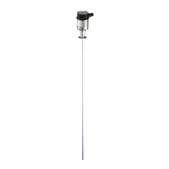
  • Seite 59 Abb. 1: LEVEL TRANSMITTER 8186 - Stabausführung Gehäusedeckel mit darunter liegendem Anzeige- und Bedienmodul (optio- nal) Gehäuse mit Elektronik Prozessanschluss Typschild Das Typschild enthält die wichtigsten Daten zur Identifikation und zum Einsatz des Gerätes: LEVEL TRANSMITTER 8186 • 4 … 20 mA/HART - Zweileiter...
  • Seite 60 Zusätzlich zum Typschild außen am Gerät finden Sie die Serien- nummer auch im Inneren des Gerätes. 3.2 Arbeitsweise Der LEVEL TRANSMITTER 8186 ist ein Füllstandsensor mit Seil- oder Einsatzbereich Stabmesssonde zur kontinuierlichen Füllstandmessung. Er ist konzipiert für industrielle Einsätze in allen Bereichen der Verfahrenstechnik und kann in aggressiven Flüssigkeiten eingesetzt...
  • Seite 61 Keinen aggressiven Medien aussetzen Vor Sonneneinstrahlung schützen Mechanische Erschütterungen vermeiden Lager- und Transport- Lager- und Transporttemperatur siehe Kapitel "Anhang - Techni- temperatur sche Daten - Umgebungsbedingungen" Relative Luftfeuchte 20 … 85 % LEVEL TRANSMITTER 8186 • 4 … 20 mA/HART - Zweileiter...
  • Seite 62 Dies gilt vor allem bei Montage im Freien, in Räumen, in denen mit Feuchtigkeit zu rechnen ist (z. B. durch Reinigungs- prozesse) oder an gekühlten bzw. beheizten Behältern. Abb. 2: Maßnahmen gegen das Eindringen von Feuchtigkeit LEVEL TRANSMITTER 8186 • 4 … 20 mA/HART - Zweileiter...
  • Seite 63 Den maximal zulässigen Druck können Sie dem Kapitel "Technische Daten" oder dem Typschild des Sensors entnehmen. 4.2 Montagehinweise Montieren Sie den LEVEL TRANSMITTER 8186 so, dass der Abstand Montageposition zu Behältereinbauten bzw. der Behälterwand min. 300 mm (12 in) beträgt.
  • Seite 64 Auch seitliche Zuführungen bei Bypassrohren haben keinen Einfluss auf die Messung. Die Messsonden können in Bypassrohren bis DN 200 montiert werden. Die maximale Temperatur ist dabei 250 °C (482 °F). LEVEL TRANSMITTER 8186 • 4 … 20 mA/HART - Zweileiter...
  • Seite 65 In Füllgütern, die zu starken Anhaftungen neigen, ist die Messung im Standrohr nicht sinnvoll. Einströmendes Füllgut Achten Sie darauf, dass die Messsonde keinen starken seitlichen Kräften ausgesetzt ist. Montieren Sie den LEVEL TRANSMITTER LEVEL TRANSMITTER 8186 • 4 … 20 mA/HART - Zweileiter...
  • Seite 66 4 Montieren 8186 an einer Stelle im Behälter, wo keine störenden Einflüsse, wie z. B. von Befüllöffnungen, Rührwerken etc. auftreten können. Abb. 6: Seitliche Belastung LEVEL TRANSMITTER 8186 • 4 … 20 mA/HART - Zweileiter...
  • Seite 67 Erdpotenzial. Im Sensor muss der Schirm direkt an die dung innere Erdungsklemme angeschlossen werden. Die äußere Erdungs- klemme am Gehäuse muss niederimpedant mit dem Potenzialaus- gleich verbunden sein. LEVEL TRANSMITTER 8186 • 4 … 20 mA/HART - Zweileiter...
  • Seite 68 Drehen nach links herausnehmen Überwurfmutter der Kabelverschraubung lösen Anschlusskabel ca. 10 cm (4 in) abmanteln, Aderenden ca. 1 cm (0.4 in) abisolieren Kabel durch die Kabelverschraubung in den Sensor schieben LEVEL TRANSMITTER 8186 • 4 … 20 mA/HART - Zweileiter...
  • Seite 69 Dichtring muss das Kabel komplett umschließen 12 Gehäusedeckel verschrauben Der elektrische Anschluss ist somit fertig gestellt. 5.3 Anschlussplan Einkammergehäuse Die nachfolgenden Abbildungen gelten sowohl für die Nicht-Ex-, als auch für die Ex-ia-Ausführung. LEVEL TRANSMITTER 8186 • 4 … 20 mA/HART - Zweileiter...
  • Seite 70 Abb. 8: Elektronik- und Anschlussraum Einkammergehäuse Serviceschnittstelle Federkraftklemmen zum Anschluss einer externen Anzeige Erdungsklemme zum Anschluss des Kabelschirms Federkraftklemmen für die Spannungsversorgung Anschlussplan Display I 2 C Abb. 9: Anschlussplan Einkammergehäuse Spannungsversorgung/Signalausgang LEVEL TRANSMITTER 8186 • 4 … 20 mA/HART - Zweileiter...
  • Seite 71 Einrasten drehen Gehäusedeckel mit Sichtfenster fest verschrauben Der Ausbau erfolgt sinngemäß umgekehrt. Das Anzeige- und Bedienmodul wird vom Sensor versorgt, ein weiterer Anschluss ist nicht erforderlich. LEVEL TRANSMITTER 8186 • 4 … 20 mA/HART - Zweileiter...
  • Seite 72 6 In Betrieb nehmen mit dem Anzeige- und Bedienmodul Abb. 10: Anzeige- und Bedienmodul einsetzen Hinweis: Falls Sie das Gerät mit einem Anzeige- und Bedienmodul zur ständigen Messwertanzeige nachrüsten wollen, ist ein erhöhter Deckel mit Sichtfenster erforderlich. LEVEL TRANSMITTER 8186 • 4 … 20 mA/HART - Zweileiter...
  • Seite 73 Sie bitte der vorhergehenden Darstellung. Ca. 10 Minuten nach der letzten Tastenbetätigung wird ein automatischer Rücksprung in die Messwertanzeige ausgelöst. Dabei gehen die noch nicht mit [OK] bestätigten Werte verloren. LEVEL TRANSMITTER 8186 • 4 … 20 mA/HART - Zweileiter...
  • Seite 74 Hilfe von PACTware bzw. DTM. HART-Betriebsart Standard Adresse 0 Da es sich beim LEVEL TRANSMITTER 8186 um ein Distanzmess- Parametrierung gerät handelt, wird die Entfernung vom Sensor bis zur Füllgutober- fläche gemessen. Um die eigentliche Füllguthöhe anzeigen zu können, muss eine Zuweisung der gemessenen Distanz zur prozentualen Höhe erfolgen.
  • Seite 75 Behälter eingeben (z. B. Distanz vom Sensor bis zum Behälterboden). Speichern der Einstellungen mit [OK] und wechseln mit [->] zum Max.-Abgleich. Max.-Abgleich durchfüh- Gehen Sie wie folgt vor: LEVEL TRANSMITTER 8186 • 4 … 20 mA/HART - Zweileiter...
  • Seite 76 Messung länger wird und der Sensor auf schnelle Messwertveränderungen nur noch verzögert reagiert. In der Regel genügt eine Zeit von wenigen Sekunden, um die Messwertanzeige weit gehend zu beruhigen. LEVEL TRANSMITTER 8186 • 4 … 20 mA/HART - Zweileiter...
  • Seite 77 Anlagen sollte zur genaueren Identifizierung der einzelnen Messstellen eine einmalige Bezeichnung eingegeben werden. Sensor-TAG Sensor Mit diesem Menüpunkt ist die Grundeinstellung abgeschlossen und Sie können nun mit der [ESC]-Taste ins Hauptmenü zurückspringen. LEVEL TRANSMITTER 8186 • 4 … 20 mA/HART - Zweileiter...
  • Seite 78 Bedienmodul. Eine Beschreibung der Funktion finden Sie in der Betriebsanleitung "Anzeige- und Bedienmodul". Folgende Daten werden mit dieser Funktion ausgelesen bzw. ge- schrieben: Messwertdarstellung Abgleich Medium Behälterform Dämpfung Linearisierungskurve Sensor-TAG Anzeigewert Anzeigeeinheit Skalierung LEVEL TRANSMITTER 8186 • 4 … 20 mA/HART - Zweileiter...
  • Seite 79 < 3.6 mA Stromausgang - Störung Anwendung - Stab-/Koaxausführung Flüssigkeit Anwendung - Seilausführung Schüttgut Die Werte folgender Menüpunkte werden mit dem "Reset" nicht auf die Resetwerte (siehe Tabelle) zurückgesetzt: Sensorspezifische Grundeinstellung. LEVEL TRANSMITTER 8186 • 4 … 20 mA/HART - Zweileiter...
  • Seite 80 Menüplan abgebildet. Eine nähere Beschreibung dieser Menüpunkte finden Sie in der Betriebsanleitung "Anzeige- und Bedienmodul". Spezialparameter sind Parameter, die mit der Bediensoftware PACTware auf der Serviceebene kundenspezifisch eingestellt werden. LEVEL TRANSMITTER 8186 • 4 … 20 mA/HART - Zweileiter...
  • Seite 81 0 % = 000.5 hl 100 % = 005.0 hl Diagnose Grundeinstellung Display ▶ Diagnose Service Info Schleppzeiger Gerätestatus Kurvenauswahl Echokurve Distanz min.: 0.234 m(d) Echokurve Darstellung der Echo- Distanz max.: 5.385 m(d) kurve LEVEL TRANSMITTER 8186 • 4 … 20 mA/HART - Zweileiter...
  • Seite 82 Jetzt aktivieren? Info Grundeinstellung Display Diagnose Service ▶ Info Gerätetyp Kalibrierdatum letzte Änderung über PC Sensormerkmale LEVEL TRANSMITTER 818X 16. März 2006 Seriennummer Softwareversion 16. März 2006 Jetzt anzeigen? 12345678 3.32.00 LEVEL TRANSMITTER 8186 • 4 … 20 mA/HART - Zweileiter...
  • Seite 83 Sollte ein Austausch des Sensors erforderlich sein, so wird das Anzeige- und Bedienmodul in das Austauschgerät gesteckt und die Daten ebenfalls im Menüpunkt "Sensordaten kopieren" in den Sensor geschrieben. LEVEL TRANSMITTER 8186 • 4 … 20 mA/HART - Zweileiter...
  • Seite 84 Online-Hilfe von PACTware und den Bürkert- DTMs enthalten. Hinweis: Bitte beachten Sie, dass zur Inbetriebnahme des LEVEL TRANS- MITTER 8186 die DTM Collection in der aktuellen Version benutzt werden muss. LEVEL TRANSMITTER 8186 • 4 … 20 mA/HART - Zweileiter...
  • Seite 85 Sie stehen damit für mehrfache Nutzung bzw. für Service- zwecke zur Verfügung. Die Bürkert DTM Collection und PACTware in der lizenzierten, professionellen Version bieten Ihnen die geeigneten Werkzeuge für eine systematische Projektspeicherung und -dokumentation. LEVEL TRANSMITTER 8186 • 4 … 20 mA/HART - Zweileiter...
  • Seite 86 Prüfen, ggf. anpassen nung zu niedrig bzw. Bürdenwi- derstand zu hoch Stromsignal grö- Elektronikeinsatz Gerät austauschen bzw. zur Repara- ßer 22 mA oder im Sensor defekt tur einsenden kleiner 3,6 mA LEVEL TRANSMITTER 8186 • 4 … 20 mA/HART - Zweileiter...
  • Seite 87 Bei Ex-Anwendungen darf nur ein Gerät und ein Elektronikeinsatz mit entsprechender Ex-Zulassung eingesetzt werden. Falls vor Ort kein Elektronikeinsatz verfügbar ist, kann dieser über die zuständige Vertretung bestellt werden. LEVEL TRANSMITTER 8186 • 4 … 20 mA/HART - Zweileiter...
  • Seite 88 Das Gerät reinigen und bruchsicher verpacken Dem Gerät das ausgefüllte Formular und eventuell ein Sicher- heitsdatenblatt beilegen Das Gerät an die jeweilige Adresse Ihrer Vertretung senden, in Deutschland direkt an das Hauptwerk LEVEL TRANSMITTER 8186 • 4 … 20 mA/HART - Zweileiter...
  • Seite 89 Mensch und Umwelt und ermöglicht eine Wiederverwendung von wertvollen Rohstoffen. Werkstoffe: siehe Kapitel "Technische Daten" Sollten Sie keine Möglichkeit haben, das Altgerät fachgerecht zu entsorgen, so sprechen Sie mit uns über Rücknahme und Entsorgung. LEVEL TRANSMITTER 8186 • 4 … 20 mA/HART - Zweileiter...
  • Seite 90 Gerätegewicht (je nach Prozessan- schluss) Stab: ø 10 mm (0.394 in) ca. 620 g/m (6.7 oz/ft) Seil: ø 4 mm (0.157 in) ca. 80 g/m (0.86 oz/ft) 325 g (11.5 oz) Straffgewicht LEVEL TRANSMITTER 8186 • 4 … 20 mA/HART - Zweileiter...
  • Seite 91 4 Nm (3 lbf ft) (0.394 in) Max. Zugbelastung bei Seil: ø 4 mm 2 KN (450 lbf) (0.157 in) Eingangsgröße Messgröße Füllstand von Flüssigkeiten und Schüttgütern > 1,6 Minimale Dielektrizitätszahl des Füllgutes ε LEVEL TRANSMITTER 8186 • 4 … 20 mA/HART - Zweileiter...
  • Seite 92 Erfüllte NAMUR-Empfehlung HART-Ausgangswerte 1. HART-Wert (Primary Value) Distanz zum Füllstand 2. HART-Wert (Secondary Value) Distanz zum Füllstand - skaliert (z. B. hl, %) > 1 mm (0.039 in) Messauflösung digital LEVEL TRANSMITTER 8186 • 4 … 20 mA/HART - Zweileiter...
  • Seite 93 Verbindliche Genauigkeitsangaben sind daher nicht möglich. Messabweichung siehe Diagramme Abhängig von den Einbaubedingungen können sich Abweichungen ergeben, die durch eine Anpassung des Abgleichs oder einer Veränderung des Mess- wertoffsets im DTM-Servicemode behoben werden können. LEVEL TRANSMITTER 8186 • 4 … 20 mA/HART - Zweileiter...
  • Seite 94 (3.15 (7.874 " " (1.575 ") 0,04 m (1.575 ") Abb. 14: Messabweichung LEVEL TRANSMITTER 8186 in Stabausführung in Füllgut Wasser Totbereich - in diesem Bereich ist keine Messung möglich Messsondenlänge 15 mm (0.591 " 5 mm (0.197 ") -5 mm (-0.197...
  • Seite 95 " " (2.756 ") 0,07 m (2.756 ") Abb. 16: Messabweichung LEVEL TRANSMITTER 8186 in Seilausführung, Messsondenlänge L < 20 m in Füllgut Wasser Totbereich - in diesem Bereich ist keine Messung möglich Messsondenlänge 15 mm (0.591 " 5 mm (0.197...
  • Seite 96 (787.4 " (2.756 ") 0,07 m (2.756 ") Abb. 18: Messabweichung LEVEL TRANSMITTER 8186 in Seilausführung, Messsondenlänge L > 20 m in Füllgut Wasser Totbereich - in diesem Bereich ist keine Messung möglich Messsondenlänge 20 mm (0.787 " 15 mm (0.591...
  • Seite 97 Prozesstemperatur (abhängig vom Dichtungswerkstoff) Elektromechanische Daten 1 x Kabelverschraubung M20 x 1,5 (Kabel: Kabeleinführung ø 5 … 9 mm), 1 x Blindstopfen M20 x 1,5 2,5 mm² (AWG 14) Federkraftklemmen für Leitungsquerschnitt LEVEL TRANSMITTER 8186 • 4 … 20 mA/HART - Zweileiter...
  • Seite 98 20 … 30 V DC EEx-ia-Gerät 20 … 36 V DC EEx-d-ia-Gerät Zulässige Restwelligkeit < 100 Hz < 1 V 100 Hz … 10 kHz < 10 mV Bürde siehe Diagramm LEVEL TRANSMITTER 8186 • 4 … 20 mA/HART - Zweileiter...
  • Seite 99 Geräte mit Zulassungen können je nach Ausführung abweichende technische Daten haben. Bei diesen Geräten sind deshalb die zugehörigen Zulassungsdokumente zu beachten. Diese sind im Gerätelieferumfang enthalten. Nicht bei Temperaturen < -40 °C (-40 °F) LEVEL TRANSMITTER 8186 • 4 … 20 mA/HART - Zweileiter...
  • Seite 100 ") ø 91 mm ø 91 mm ") ") M20x1,5/ M20x1,5/ ½ NPT ½ NPT Abb. 22: Gehäuseausführungen Gehäuse mit Klarsichtdeckel für Anzeige- und Bedienmodul Gehäuse ohne Anzeige- und Bedienmodul LEVEL TRANSMITTER 8186 • 4 … 20 mA/HART - Zweileiter...
  • Seite 101 ø 4mm ") ø 10 mm ø 20mm ") ") Abb. 23: LEVEL TRANSMITTER 8186 - Flanschausführung Sensorlänge, siehe Kapitel "Technische Daten" Seilausführung mit Flanschanschluss Stabausführung mit Flanschanschluss Tri-Clamp Rohrverschraubung LEVEL TRANSMITTER 8186 • 4 … 20 mA/HART - Zweileiter...
  • Seite 102 10 Anhang LEVEL TRANSMITTER 8186 • 4 … 20 mA/HART - Zweileiter...
  • Seite 103 10 Anhang LEVEL TRANSMITTER 8186 • 4 … 20 mA/HART - Zweileiter...
  • Seite 104 The smart choice of Fluid Control Systems www.buerkert.com 32342-DE-100428...
  • Seite 105 Mise en service LEVEL TRANSMITTER 8186 4 … 20 mA/HART - deux fils...
  • Seite 106 Éliminer les défauts ......36 LEVEL TRANSMITTER 8186 • 4 … 20 mA/HART - deux fils...
  • Seite 107 Pour une application et un fonctionnement sûrs de votre LEVEL TRANSMITTER 8186, nous vous proposons des accessoires et pièces de rechange dont voici les documentations : Notice de mise en service "Préamplificateur LEVEL TRANSMIT- TER 818X" LEVEL TRANSMITTER 8186 • 4 … 20 mA/HART - deux fils...
  • Seite 108 Étape de déroulement d'une action Cette flèche indique l'étape de déroulement d'une action. Chronologie de déroulement d'une action Le déroulement d'une action est numéroté dans son ordre chronolo- gique. LEVEL TRANSMITTER 8186 • 4 … 20 mA/HART - deux fils...
  • Seite 109 Portez toujours l'équipement de protection personnel nécessaire en travaillant sur et avec l'appareil. 2.2 Application conforme à sa destination Le LEVEL TRANSMITTER 8186 est un capteur pour la mesure de niveau continue. Vous trouverez des informations plus détaillées concernant le domaine d'application au chapitre "Description du produit".
  • Seite 110 CE. Avec le marquage CE, nous confirmons que le contrôle a été effectué avec succès. 2.7 Recommandations NAMUR satisfaites En ce qui concerne la compatibilité, le LEVEL TRANSMITTER 8186 et ses composants de réglage et d'affichage satisfont à la recomman- dation NAMUR NE 53.
  • Seite 111 Le LEVEL TRANSMITTER 8186 est composé des éléments : Composants Raccord process avec sonde de mesure Boîtier avec électronique Couvercle du boîtier, en option avec module de réglage et d'affichage LEVEL TRANSMITTER 8186 • 4 … 20 mA/HART - deux fils...
  • Seite 112 également un numéro de série à l'intérieur de l'appareil. 3.2 Mode de fonctionnement Le LEVEL TRANSMITTER 8186 est un capteur de niveau avec sonde Domaine d'application câble ou tige destiné à la mesure de niveau continue. Il est conçu pour les applications industrielles dans tous les secteurs de la technique des procédés et peut être utilisé...
  • Seite 113 Ne pas entreposer à l'extérieur Entreposer dans un lieu sec et sans poussière Ne pas exposer à des produits agressifs Protéger contre les rayons du soleil Éviter des secousses mécaniques LEVEL TRANSMITTER 8186 • 4 … 20 mA/HART - deux fils...
  • Seite 114 Température de transport et de stockage voir au chapitre "Annexe de stockage et de trans- - Caractéristiques techniques - Conditions ambiantes" Humidité relative de l'air 20 … 85 % port LEVEL TRANSMITTER 8186 • 4 … 20 mA/HART - deux fils...
  • Seite 115 à de l'humidité (due par exemple à des processus de nettoyage) ou encore dans des cuves réfrigérées ou chauffées. Fig. 2: Mesures prises contre l'infiltration d'humidité LEVEL TRANSMITTER 8186 • 4 … 20 mA/HART - deux fils...
  • Seite 116 4.2 Consignes de montage Montez le LEVEL TRANSMITTER 8186 de façon à ce qu'il soit à un Position de montage écart d'au moins 300 mm (12 in) de la paroi ou des obstacles fixes de la cuve.
  • Seite 117 PTFE, la mise de place de rondelles ressorts sur les boulons de fixation. Les vis de la bride du capteur LEVEL TRANSMITTER 8186 doivent toujours être vissées avec un couple de serrage de l'ordre de 60 Nm (44 lbf ft) pour assurer l'étanchéité...
  • Seite 118 DN 200. La température maximale en est de 250 °C (482 °F). Si le LEVEL TRANSMITTER 8186 doit être installé dans des tubes de mesure ou bypass, il faut éviter tout contact de la sonde avec la paroi du tube.
  • Seite 119 Installez le LEVEL TRANSMITTER 8186 à un endroit de la cuve où il ne sera pas soumis à des influences perturbatrices telles que par exemple orifices de remplissage, agitateurs etc. LEVEL TRANSMITTER 8186 • 4 … 20 mA/HART - deux fils...
  • Seite 120 4 Montage Fig. 6: Charge latérale LEVEL TRANSMITTER 8186 • 4 … 20 mA/HART - deux fils...
  • Seite 121 à la terre être raccordé directement à la borne de terre interne. La borne de terre externe se trouvant sur le boîtier doit être reliée à basse impédance au conducteur d'équipotentialité. LEVEL TRANSMITTER 8186 • 4 … 20 mA/HART - deux fils...
  • Seite 122 Enlevez la gaine du câble sur 10 cm (4 in) env. et dénudez l'extrémité des conducteurs sur 1 cm (0.4 in) env. Introduisez le câble dans le capteur en le passant par le presse- étoupe. LEVEL TRANSMITTER 8186 • 4 … 20 mA/HART - deux fils...
  • Seite 123 Le raccordement électrique est maintenant terminé. 5.3 Schéma de raccordement boîtier à chambre unique Les schémas suivants sont valables aussi bien pour la version non-Ex que pour la version Ex-ia. LEVEL TRANSMITTER 8186 • 4 … 20 mA/HART - deux fils...
  • Seite 124 Borne de terre pour le raccordement du blindage du câble Bornes auto-serrantes pour l'alimentation de tension Schéma de raccorde- ment Display I 2 C Fig. 9: Schéma de raccordement boîtier à chambre unique Alimentation de tension/sortie signal LEVEL TRANSMITTER 8186 • 4 … 20 mA/HART - deux fils...
  • Seite 125 Le démontage s'effectue de la même façon, mais en sens inverse. Le module de réglage et d'affichage est alimenté par le capteur, un autre raccordement n'est donc pas nécessaire. LEVEL TRANSMITTER 8186 • 4 … 20 mA/HART - deux fils...
  • Seite 126 Si le module de réglage et d'affichage doit demeurer définitivement dans votre appareil pour disposer en permanence d'un affichage des valeurs de mesure, il vous faudra un plus haut couvercle muni d'un hublot. LEVEL TRANSMITTER 8186 • 4 … 20 mA/HART - deux fils...
  • Seite 127 10 minutes après le dernier appui sur une touche. À ce moment là, les valeurs n'ayant pas encore été validées avec [OK] seront perdues. LEVEL TRANSMITTER 8186 • 4 … 20 mA/HART - deux fils...
  • Seite 128 Au menu principal "Réglage de base", il est nécessaire pour obtenir un réglage optimal de la mesure de sélectionner les sous-menus l'un après l'autre et de leur attribuer les paramètres corrects. LEVEL TRANSMITTER 8186 • 4 … 20 mA/HART - deux fils...
  • Seite 129 (par exemple distance entre capteur et fond de la cuve). Sauvegardez vos réglages avec [OK] et allez avec [->] au réglage maxi. Effectuer le réglage Procédez comme suit : max. LEVEL TRANSMITTER 8186 • 4 … 20 mA/HART - deux fils...
  • Seite 130 Ce temps d'intégration peut se trouver entre 0 et 999 secondes. Veuillez cependant tenir compte que le temps de réaction de la mesure totale sera prolongé et que la réaction du LEVEL TRANSMITTER 8186 • 4 … 20 mA/HART - deux fils...
  • Seite 131 TAG capteur Capteur LEVEL TRANSMITTER 8186 • 4 … 20 mA/HART - deux fils...
  • Seite 132 "Module de réglage et d'affichage". Cette fonction permet la lecture et/ou la saisie des données suivantes : Représentation de la valeur de mesure Réglage Produit Forme de la cuve Atténuation Courbe de linéarisation LEVEL TRANSMITTER 8186 • 4 … 20 mA/HART - deux fils...
  • Seite 133 Application - version câble Solide en vrac En effectuant un "Reset", les valeurs des menus suivants ne seront pas remises aux valeurs reset (voir tableau) : Réglage de base spécifique au capteur. LEVEL TRANSMITTER 8186 • 4 … 20 mA/HART - deux fils...
  • Seite 134 "Module de réglage et d'affichage". Les paramètres spéciaux sont des paramètres qui seront réglés selon les spécifications du client au niveau du menu service via le logiciel de con- figuration PACTware. LEVEL TRANSMITTER 8186 • 4 … 20 mA/HART - deux fils...
  • Seite 135 Info Index suiveur Etat du capteur Sélection de la courbe Courbe échos Distance min. : 0.234 m(d) Courbe échos Représentation de la Distance max. : 5.385 m(d) courbe échos LEVEL TRANSMITTER 8186 • 4 … 20 mA/HART - deux fils...
  • Seite 136 Date de l'étalonnage Dernière modification via PC Caractéristiques du capteur LEVEL TRANSMITTER 818X 16 mars 2006 Numéro de série Version logicielle 16 mars 2006 Afficher maintenant ? 12345678 3.32.00 LEVEL TRANSMITTER 8186 • 4 … 20 mA/HART - deux fils...
  • Seite 137 à des fins de maintenance. Si le LEVEL TRANSMITTER 8186 est équipé d'un module de réglage et d'affichage, les données les plus importantes pourront être lues du capteur vers le module de réglage et d'affichage. La procédure vous sera décrite dans la notice technique "Module de réglage et...
  • Seite 138 PACTware et des DTM Bürkert. Remarque: N'oubliez pas que pour la mise en oeuvre de votre LEVEL TRANSMITTER 8186, il vous faut la collection DTM dans sa version actuelle. LEVEL TRANSMITTER 8186 • 4 … 20 mA/HART - deux fils...
  • Seite 139 à des fins de maintenance ou de service. La collection DTM Bürkert et PACTware vous offrent dans leur version professionnelle (avec licence) les outils appropriés pour une docu- mentation et une sauvegarde systématiques de projet. LEVEL TRANSMITTER 8186 • 4 … 20 mA/HART - deux fils...
  • Seite 140 C'est à l'exploitant de l'installation qu'il incombe la responsabilité de de pannes prendre les mesures appropriées pour éliminer les défauts survenus. Le LEVEL TRANSMITTER 8186 vous offre une très haute sécurité de Causes des défauts fonctionnement. Toutefois, des défauts peuvent apparaître pendant le fonctionnement de l'appareil.
  • Seite 141 Comportement après Suivant la cause du défaut et les mesures prises pour l'éliminer, il élimination des défauts faudra le cas échéant recommencer les étapes décrites au chapitre "Mise en service". LEVEL TRANSMITTER 8186 • 4 … 20 mA/HART - deux fils...
  • Seite 142 Prière de joindre à l'appareil le formulaire rempli et éventuellement une fiche de sécurité Prière de retourner l'appareil à l'adresse de votre agence respective, en Allemagne directement à l'usine-mère LEVEL TRANSMITTER 8186 • 4 … 20 mA/HART - deux fils...
  • Seite 143 Au cas où vous n'auriez pas la possibilité de faire recycler l'ancien appareil par une entreprise spécialisée, contactez-nous, nous vous conseillerons sur les possibilités de reprise et de recyclage. LEVEL TRANSMITTER 8186 • 4 … 20 mA/HART - deux fils...
  • Seite 144 Tige : ø 10 mm (0.394 in) env. 620 g/m (6.7 oz/ft) Câble : ø 4 mm (0.157 in) env. 80 g/m (0.86 oz/ft) 325 g (11.5 oz) Poids tenseur LEVEL TRANSMITTER 8186 • 4 … 20 mA/HART - deux fils...
  • Seite 145 Charge de traction max. avec câble : ø 4 mm 2 KN (450 lbf) (0.157 in) Grandeur d'entrée Grandeur de mesure Niveau de liquides et solides en vrac/pulvérulents > 1,6 Constante diélectrique minimum du produit ε LEVEL TRANSMITTER 8186 • 4 … 20 mA/HART - deux fils...
  • Seite 146 1. Valeur HART (Primary Value) Distance au niveau 2. Valeur HART (Secondary Value) Distance par rapport au niveau - gradué (par exemple hl, %) > 1 mm (0.039 in) Résolution de mesure numérique LEVEL TRANSMITTER 8186 • 4 … 20 mA/HART - deux fils...
  • Seite 147 En fonction des conditions de montage, il peut y avoir des écarts qui peuvent être supprimés en adaptant le réglage ou en modifiant l'offset de la valeur de mesure en mode de service DTM. LEVEL TRANSMITTER 8186 • 4 … 20 mA/HART - deux fils...
  • Seite 148 " (1.575 ") 0,04 m (1.575 ") Fig. 14: Écart de mesure LEVEL TRANSMITTER 8186 en version tige dans l'eau Zone morte - Aucune mesure n'est possible dans cette zone Longueur de la sonde 15 mm (0.591 " 5 mm (0.197...
  • Seite 149 0,07 m (2.756 ") Fig. 16: Écart de mesure LEVEL TRANSMITTER 8186 en version à câble, longueur de la sonde de mesure L < 20 m dans l'eau Zone morte - Aucune mesure n'est possible dans cette zone Longueur de la sonde 15 mm (0.591...
  • Seite 150 0,07 m (2.756 ") Fig. 18: Écart de mesure LEVEL TRANSMITTER 8186 en version à câble, longueur de la sonde de mesure L > 20 m dans l'eau Zone morte - Aucune mesure n'est possible dans cette zone Longueur de la sonde 20 mm (0.787...
  • Seite 151 1 x presse-étoupe M20 x 1,5 (ø du câble : Entrée de câble 5 … 9 mm), 1 x obturateur M20 x 1,5 2,5 mm² (AWG 14) Bornes à ressort pour section de conducteur jusqu'à LEVEL TRANSMITTER 8186 • 4 … 20 mA/HART - deux fils...
  • Seite 152 20 … 36 V DC Appareil EEx d ia Ondulation résiduelle tolérée < 100 Hz < 1 V 100 Hz … 10 kHz < 10 mV Charge ohmique voir diagramme LEVEL TRANSMITTER 8186 • 4 … 20 mA/HART - deux fils...
  • Seite 153 Ceux-ci font partie de la livraison des appareils. Pas à des températures < -40 °C (-40 °F) LEVEL TRANSMITTER 8186 • 4 … 20 mA/HART - deux fils...
  • Seite 154 ") M20x1,5/ M20x1,5/ ½ NPT ½ NPT Fig. 22: Versions de boîtiers Boîtier avec couvercle transparent pour module de réglage et d'affichage Boîtier sans module de réglage et d'affichage LEVEL TRANSMITTER 8186 • 4 … 20 mA/HART - deux fils...
  • Seite 155 Fig. 23: LEVEL TRANSMITTER 8186 - version à bride Longueur du capteur, voir au chapitre "Caractéristiques techniques" Version câble avec raccord à bride Version tige avec raccord à bride Tri-Clamp Raccord union LEVEL TRANSMITTER 8186 • 4 … 20 mA/HART - deux fils...
  • Seite 156 The smart choice of Fluid Control Systems www.burkert.com 32342-FR-100604...