SICK OD Mini Pro Kurzanleitung
English
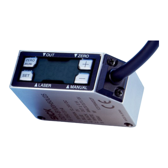
Distance sensor OD Mini Pro
with display and serial output
Operating Instructions
OD Mini Pro
EN/IEC 60825-1:2014
Complies with 21 CFR 1040.10 and 1040.11
except for deviations pursuant to
Laser Notice No. 50, dated June 24, 2007
D-79183 Waldkirch, Germany
Manufactured in :
Australia
Phone +61 3 9457 0600
Laser radiation – Laser class 1
Austria
Phone +43 22 36 62 28 8-0
Identical laser class for issue EN/IEC 60825-1:2007
Belgium/Luxembourg
Phone +32 2 466 55 66
Brazil
Safety notes
Phone +55 11 3215-4900
Canada
Phone +1 905 771 14 44
•
CAUTION: Use of controls or adjustments or performance
Czech Republic
Phone +420 2 57 91 18 50
of procedures other than those specified herein may re-
Chile
Phone +56 2 2274 7430
sult in hazardous radiation exposure.
China
•
Phone +86 20 2882 3600
Read the Operating Instructions before starting opera-
Denmark
tion.
Phone +45 45 82 64 00
Finland
•
Phone +358-9-2515 800
Connection, mounting and setting must be performed by
France
qualified personnel.
Phone +33 1 64 62 35 00
Germany
•
Protect devices from moisture and contamination during
Phone +49 211 5301-301
Hong Kong
commissioning.
Phone +852 2153 6300
Hungary
•
Not free of paint-wetting impairment substances.
Phone +36 1 371 2680
•
India
No safety component pursuant to EU directive.
Phone +91 22 6119 8900
Israel
Phone +972 4 6881000
Intended use
Italy
Phone +39 02 274341
The distance sensor OD Mini Pro is an optoelectronic sensor
Japan
Phone +81 3 5309 2112
and is used for optical determination of object distances
Malaysia
Phone +6 03 8080 7425
without contact.
Mexico
Phone +52 (472) 748 9451
Netherlands
Scope of delivery
Phone +31 30 2044 000
Sensor OD Mini Pro, 2x M3 screws, laser warning label and
Please find detailed addresses and further locations in all major industrial
nations at www.sick.com
Operating Instructions
Commissioning
! Mount sensor.
SICK AG | Erwin-Sick-Str. 1 | 79183 Waldkirch | Germany | www.sick.com
— For steps, eccentricity measurements of round
objects and strong contrast changes, consider the
preferred direction of the sensor. See Fig. C.
" Align sensor.
— Align sensor so that object is within measuring range.
See Tab. G. Display indicates distance from center of
measuring range. If 9999 is displayed, measurement
is not possible. Object may be out of measuring
range.
§ Electrical connection: Connect cable socket tension free
and tighten the screw. See Fig. E.
$ Connect sensor to supply voltage. Operating display is
lit. Consider warm-up time for best measuring results.
See Tab. G.
% Perform parameterization. See Fig. H and Tab. I/J.
Operation via operating keys
The result of the taught-in switching behaviour can be que-
ried via the serial interface (see table J for details).)
Perform teach-in (see Fig. F, Fig. H and Tab. I)
! Align distance sensor with the distance to be taught-in.
" Select teach option via parameter MoDE and teach-in
switching point:
— 1Pt (1-point teach): Switching point FAr. See Fig. F1.
— 2Pt (2-point teach): Switching point nEAr and FAr.
See Fig. F2.
— Obsb (background): Switching point ObSb.
See Fig. F3.
§ If necessary, enter hysteresis (hYst) and tolerance (tol).
See Fig. H and Tab. I.
Zeroing
The distance sensor is in RUN mode.
•
Set value to zero: Press key ZERO/RUN for 2 seconds.
The display shows 0.00 when successfully reset.
•
Recover value: Press key ZERO/RUN for 4 seconds.
Key lock (see Fig. H)
Identische Laserklasse für Ausgabe EN/IEC 60825-1:2007
The distance sensor is in RUN mode.
•
On: Press – and + key for 3 seconds simultaneously.
Sicherheitshinweise
•
Off: Press – and + key for 3 seconds simultaneously.
•
Vor allen Arbeiten die Betriebsanleitung lesen.
Maintenance
•
Anschluss, Montage und Einstellung nur durch Fachper-
sonal.
It is recommended to regularly clean the external lens
•
Gerät bei Inbetriebnahme vor Feuchte und Verunreinigung
surfaces and to check the screw connections and plug
schützen.
connections.
•
Nicht frei von lackbenetzungsstörenden Substanzen.
•
Kein Sicherheitsbauteil gemäß EU-Maschinenrichtlinie.
Bestimmungsgemäße Verwendung
Der Distanzsensor OD Mini Pro ist ein optoelektronischer
Sensor und wird zur optischen, berührungslosen Distanz-
messung eingesetzt.
Lieferumfang
OD Mini Pro Sensor, Befestigungswinkel, 2x M3 Schrauben,
Laserwarnschild und Betriebsanleitung
Inbetriebnahme
! Sensor montieren.
— Bei Stufen, Exzentrizitätsmessungen von runden Ob-
jekten und bei starken Kontrastwechseln Vorzugsrich-
tung des Sensors beachten. Siehe Abb. C.
" Sensor ausrichten.
— Das Objekt muss im Messbereich liegen. Siehe
Tab. G. Das Display zeigt den Abstand von der Mess-
bereichsmitte an. Wird 9999 angezeigt, ist keine Mes-
sung möglich. Objekt liegt z. B. außerhalb des Mess-
bereiches.
§ Elektrischer Anschluss: Leitungsdose spannungsfrei auf-
stecken und festschrauben. Siehe Abb. E.
8017923/ZMO9/2017-06/HS_8M
$ Sensor an Versorgungsspannung legen. Betriebsanzeige
leuchtet. Für optimale Messergebnisse Aufwärmzeit be-
achten. Siehe Tab. G.
% Parametrierung durchführen. Siehe Abb. H und Tab. I/J.
Bedienung über Bedientasten
NFPA79 applications only.
Das Ergebnis des eingelernten Schaltverhaltens kann über
Adapters providing field
die serielle Schnittstelle abgefragt werden. (Details siehe
wiring leads are available.
as marked on device
Refer to the product information.
Tab. J)
Teach-in durchführen (siehe Abb. F, Abb. H und Tab. I)
! Distanzsensor auf einzulernende Distanz ausrichten.
" Teach-Option über Parameter MoDE wählen und Schalt-
New Zealand
punkt einlernen:
Phone +64 9 415 0459
Norway
Phone +47 67 81 50 00
— 1Pt (1-Punkt-Teach): Schaltpunkt FAr. Siehe Abb. F1.
Poland
Phone +48 22 539 41 00
— 2Pt (2-Punkt-Teach): Schaltpunkt nEAr und FAr. Sie-
Romania
Phone +40 356 171 120
he Abb. F2.
Russia
Phone +7 495 775 05 30
— Obsb (Hintergrund): Schaltpunkt ObSb. Siehe Abb. F3.
Singapore
Phone +65 6744 3732
§ Ggf. Hysterese (hYst) und Toleranz (tol) eingeben. Siehe
Slovakia
Phone +421 482 901201
Abb. H und Tab. I.
Slovenia
Phone +386 591 788 49
South Africa
Nullpunktverschiebung
Phone +27 11 472 3733
South Korea
Phone +82 2 786 6321
Der Distanzsensor befindet sich im RUN-Mode.
Spain
Phone +34 93 480 31 00
•
Wert auf Null setzen: Taste ZERO/RUN für 2 Sekunden
Sweden
Phone +46 10 110 10 00
drücken. Bei erfolgreicher Rücksetzung zeigt das Display
Switzerland
Phone +41 41 619 29 39
0.00 an.
Taiwan
Phone +886 2 2375-6288
•
Wert wieder herstellen: Taste ZERO/RUN für 4 Sekunden
Thailand
Phone +66 2645 0009
drücken.
Turkey
Phone +90 216 528 50 00
Tastensperre (siehe Abb. H)
United Arab Emirates
Phone +971 4 88 65 878
United Kingdom
Der Distanzsensor befindet sich im RUN-Mode.
Phone +44 1727 831121
USA
•
Ein: Taste – und + gleichzeitig für 3 Sekunden drücken.
Phone +1 800 325 7425
Vietnam
•
Aus: Taste – und + gleichzeitig für 3 Sekunden drücken.
Phone +84 945452999
Wartung
Es wird empfohlen in regelmäßigen Abständen die optischen
Grenzflächen zu reinigen und Verschraubungen, sowie Steck-
verbindungen zu überprüfen.
Subject to change without notice
Irrtümer und Änderungen vorbehalten
Deutsch
Distanzsensor OD Mini Pro
mit Display und serieller Schnittstelle
Betriebsanleitung
G
Technical Data / Technische Daten
EN/IEC 60825-1:2014
Complies with 21 CFR 1040.10 and 1040.11
except for deviations pursuant to
Laser Notice No. 50, dated June 24, 2007
D-79183 Waldkirch, Germany
Manufactured in :
Measuring range /Messbereich
Laserstrahlung – Laserklasse 1
15 ± 5 mm
35 ± 15 mm
100 ± 50 mm
Housing material /
Gehäusematerial
Stainless steel / Edelstahl
Aluminum / Aluminium
Interface / Schnittstelle
RS-485
Connection / Anschluss
M8 plug, 4-pin / M8-Stecker, 4-polig
Cable with M12 plug, 5-pin /
Leitung mit M12-Stecker, 5-polig
1)
At set averaging 512
2)
Constant ambient conditions
3)
Measurement on 90 % remission (ceramic, white)
For best performance consider warm up time ≤ 5 min.
4)
A
Dimensions / Abmessungen
OD1-xxxxHxxxxx
Edelstahl/Stainless steel
31
(1.22)
3
2 x M3
(0.12)
1
16
(0.63)
All dimensions in mm (inch)
1
Type with 30 cm cable with M12, 5 pin connector /
Variante mit Anschlussleitung 30 cm mit Stecker M12, 5-pin
2
Optical axis / Optische Achse
3
Distance optical axis sender to receiver /
Abstand optische Achse Sender zu Empfänger:
OD1-B015x: 8.1 mm / OD1-B35x: 12.6 mm /
OD1-B100x: 15.5 mm
4
Optical axis receiver / Optische Achse Empfänger
5
Optical axis sender / Optische Achse Sender
C
Preferred mounting direction /
Vorzugsrichtung der Sensormontage
D
Measurement value scaling /
Messwertskalierung
Measured
value
in Hex
7FFF
2
1
Near end
Far end of
of measuring
measuring
range
Model
OD1-B015x05xxx OD1-B035x15xxx
Range
±5mm
±15mm
Unit
1μm
10μm
Data
EC78h
1388h
FA24h
05DCh
(Hex)
1
2
1
2
Resolution
1)
Repeatability
Linearity
3), 4
1), 2)
Auflösung
1)
Reproduzier-
Linearität
3), 4
OD1-
barkeit
1), 2)
B015
05
1 μm
3 μm
± 10 μm
B035
15
6 μm
9 μm
± 30 μm
B100
50
20 μm
30 μm
± 100 μm
H
C
A1
4
5
1)
Bei Mittelwerteinstellung 512
2)
Konstante Rahmenbedingungen
3)
Messung auf 90 % Remission (Keramik, weiß)
Für optimale Messergebnisse max. Aufwärmzeit von 5 Min. beachten.
4)
OD1-xxxxCxxxxx
Aluminium/Aluminum
17
31
17,8
(1.22)
(0.67)
(0.7)
3
1.1
2 x M3
2
(0.12)
2
(0.04)
4
3
1
5
16
(0.63)
E
Electrical connection / Elektrischer Anschluss
OD1-Bxxxxxxx1x
M8, 4-pin
1
2
4
brn
L+ (12 V ... 24 V)
2
wht
RS-485 (B)
3
blu
0 V
1
3
blk
4
RS-485 (A)
F
Switching behavior / Schaltverhalten
The result of the taught-in switching behaviour can be queried via the serial interface (see table J for details). / Das
Ergebnis des eingelernten Schaltverhaltens kann über die serielle Schnittstelle abgefragt werden (Details siehe Tab. J)
F1
F2
ModE: 1Pt
ModE: 2Pt
1
FAr
OD
Min
Max
hYSt
RUN Mode
RUN Mode
SET
MEnu
–
+
–
+
SET
ModE
2Pt
1pt
obSb
SET
Teach-in current
–
+
distance
SET
FAr
tch
ZERO
RUN
RUN Mode
Distance
range
OD1-B100x50xxx
RUN Mode
±50mm
10μm
EC78h
1388h
1
2
OD1-
Typ. light spot
dimension
Light source
Laser, red
(Distance)
Laser protection class
1 (EN 60825-1)
1)
Typ. Lichtfleckab-
Response time
2)
2 ms / 4 ms / 8 ms / 16 ms / Auto
messung (Distanz)
Measuring frequency
2 kHz / 1 kHz / 500 Hz / 250 Hz / Auto
Supply voltage V
4)
12 V DC (–5 %) ... 24 V DC (+10 %)
S
Power consumption
≤ 1,92 W (without load, incl. current output)
700 μm x 500 μm
Warm up time
≤ 5 min
(15 mm)
Material
Housing: stainless steel or aluminum,
800 μm x 450 μm
Front window: PPSU
(35 mm)
Weight
with stainless steel housing: 70 g,
700 μm x 600 μm
with aluminum housing: 40 g
(100 mm)
Enclosure rating
IP 67
Protection class
Ambient temperature
Operation: –10 ... +50 °C at rel. humidity
35 % ... 95 % (not condensing)
Storage: –20 ... +60 °C
Typ. ambient light safety
Artificial light: ≤ 3.000 lx;
Sunlight: ≤ 10.000 lx
Temperature drift
± 0.08 % FS/K (FS: Full Scale: Measuring
range of sensor)
Vibration resistance
10 ... 55 Hz (Amplitude 1,5 mm; x-, y- and
z-axis 2 hours each)
Shock resistance
50 G (x-, y- and z-axis 3 times each)
1)
Wavelength 655 nm, max. output: 390 μW
2)
At fixed sensitivity setting and averaging =1
3)
Sampling rate 500µs: 2 ... 7.5 ms response time/ sampling rate 1000µs:
4 ... 15 ms response time
4)
When using analog voltage output reduced to DC 18 V (–5 %) ... DC 24 V
(+ 10 %)
B
Display and operating elements /
Display und Bedienelemente
1
2
OUT
ZERO
+
ZERO
RUN
5
–
1.1
SET
(0.04)
LASER
MANUAL
4
3
1
Status switching output /
Status Schaltausgang
4
2
Status zeroing /
Status Nullpunktverschiebung
3
3
Status Teach mode /
5
Status Teach-Modus
Status laser
4
Status Laser
Minus sign for measured value indicator /
5
Minuszeichen für Messwertanzeige
OD1-Bxxxxxxx2x
M12, 5-pin
brn
brown
braun
wht
white
weiß
1
4
5
3
brn
L+ (12 V ... 24 V)
blu
blue
blau
2
wht
blk
black
schwarz
RS-485 (B)
gra
grey
grau
3
blu
0 V
4
1
2
blk
RS-485 (A)
1 not connected
5
gra
nicht belegt
nc
1
F3
ModE: obSb
1
1
2
nEAr
FAr
obSb
hYSt
hYSt
OD
OD
Min
Max
Min
Max
hYSt
hYSt
tol
tol
RUN Mode
SET
SET
MEnu
MEnu
–
+
–
+
–
+
–
+
SET
SET
ModE
ModE
2Pt
1pt
obSb
2Pt
1pt
obSb
SET
SET
Teach-in current
Teach-in current
–
+
–
+
distance
distance
SET
SET
nEAr
obSb
tch
tch
Teach-in current
ZERO
–
+
RUN
distance
SET
RUN Mode
FAr
tch
ZERO
RUN
Switching
point
Hysteresis
1. Teach-in point
1
2
2. Teach-in point
OD1-
Lichtsender
Laser, rot
Laserschutzklasse
1 (EN 60825-1)
1)
3)
Ansprechzeit
2)
2 ms / 4 ms / 8 ms / 16 ms / Auto
3)
Messfrequenz
2 kHz / 1 kHz / 500 Hz / 250 Hz / Auto
Versorgungsspannung U
4)
12 V DC (–5 %) ... 24 V DC (+10 %)
V
Leistungsaufnahme
≤ 1,92 W (ohne Last, inkl. Stromausgang)
Aufwärmzeit
≤ 5 min
Material
Gehäuse: Edelstahl oder Aluminium,
Frontscheibe: PPSU
Gewicht
mit Edelstahlgehäuse: 70 g,
mit Aluminiumgehäuse: 40 g
Schutzart
IP 67
Schutzklasse
Umgebungsbedingungen
Betrieb: –10 ... +50 °C bei rel. Feuchte
35 % ... 95 % (nicht kondensierend)
Lagerung: –20 ... +60 °C
Fremdlichtsicherheit
Künstliches Licht: ≤ 3.000 lx;
Sonnenlicht: ≤ 10.000 lx
Temperaturdrift
± 0,08 % FS/K (FS: Full Scale: Messbereich
des Sensors)
Vibrationsfestigkeit
10 ... 55 Hz (Amplitude 1,5 mm; x-, y- und
z-Achse jeweils 2 Stunden)
Stoßfestigkeit
50 G (x-, y- und z-Achse jeweils 3 Mal)
1)
Wellenlänge 655 nm, max. Leistung: 390 μW
2)
Bei fixer Empfindlichkeitseinstellung und Mittelwertbildung =1
3)
Messrate 500µs: 2 ... 7,5 ms Ansprechzeit/Messrate 1000µs: 4 ... 15 ms
Ansprechzeit
4)
Bei Nutzung des analogen Spannungsausganges reduzierte Grenzen auf
DC 18 V (–5 %) ... DC 24 V (+ 10 %)

Verwandte Anleitungen für SICK OD Mini Pro


Inhaltszusammenfassung für SICK OD Mini Pro
- Seite 1 Scope of delivery Phone +31 30 2044 000 Wartung Sensor OD Mini Pro, 2x M3 screws, laser warning label and Es wird empfohlen in regelmäßigen Abständen die optischen Please find detailed addresses and further locations in all major industrial nations at www.sick.com Operating Instructions Grenzflächen zu reinigen und Verschraubungen, sowie Steck-...
- Seite 2 Empfangszeile des Sensors und das Funktionsprinzip für die Parameter tHrE und NtoP – die Lichtverteilkurve kann beim OD Mini Pro nicht ausgelesen Example for two signal peaks/ Beispiel für zwei Signalspitzen: werden. 1 Ntop: Measured barycenter/Gemessener Lichtschwerpunkt (Pt_1/Pt_2)
- Seite 3 Setting Address/ DATA1 (upper) DATA2 (lower) Description Communication (English) Parameter Display setting Address Communication method RS-485 Half Duplex (Multi-drop protocol is not supported) Parameter 00h / 01h ON / OFF Transmission code Binary Hysteresis Address Data length 8bit Parameter Upper data Lower data Stop length 1bit...
- Seite 4 Einstellung Adresse/ DATEN1 DATEN2 (untere) Beschreibung Kommunikation (Deutsch) Parameter (obere) Alarmeinstellung Adresse Kommunikationsmethode RS-485 Halbduplex (Multidrop-Protokoll wird nicht unterstützt) Parameter 00h / 01h Clamp / Hold Sendecode binär Alarm - Hold und Adresse Datenlänge 8 Bit Clamp Parameter Obere Daten Untere Daten Stoppbitlänge 1 Bit...