Herunterladen Inhalt Inhalt Diese Seite drucken
Bpt TH400TX-RX Gebrauchsanweisung

Bpt TH400TX-RX Gebrauchsanweisung

Thermoprogram programmierbarer temperaturregler mit funkfrequenzsteuerung
Inhaltsverzeichnis

Werbung

Verfügbare Sprachen

Verfügbare Sprachen

PROGRAMMABLE THERMO-
GB
STAT THERMOPROGRAM WITH
RADIOFREQUENCY REMOTE
CONTROL
THERMOPROGRAM
D
PROGRAMMIERBARER
TEMPERATURREGLER MIT
FUNKFREQUENZSTEUERUNG
THERMOSTAT ELECTRONIQUE
F
PROGRAMMABLE A COMMAN-
DE RADIO
TH 400TX-RX
TH402TX-RX
1 2 3 4 5 6 7
R
T
T3
T2
T1
0
4
8
12
ON
0
23
1
7
C
16
20
INSTRUCTIONS
FOR USE
GEBRAUCHS-
ANWEISUNG
MODE
D'EMPLOI

Werbung

Kapitel

Inhaltsverzeichnis
loading

Inhaltszusammenfassung für Bpt TH400TX-RX

  • Seite 1 PROGRAMMABLE THERMO- STAT THERMOPROGRAM WITH RADIOFREQUENCY REMOTE CONTROL THERMOPROGRAM PROGRAMMIERBARER TEMPERATURREGLER MIT FUNKFREQUENZSTEUERUNG THERMOSTAT ELECTRONIQUE PROGRAMMABLE A COMMAN- DE RADIO TH 400TX-RX TH402TX-RX INSTRUCTIONS FOR USE 1 2 3 4 5 6 7 GEBRAUCHS- ANWEISUNG MODE D’EMPLOI...
  • Seite 2 Congratulations on your purchase RECOMMENDATIONS DISPOSAL of the TH400TX-RX and TH402TX- FOR THE INSTALLER RX thermostat. To get the best Do not litter the environment with performance and make the best packing material: make sure it is use of the features and functions of •...
  • Seite 3 Thermoprogram TH400TX-RX is The TH400RX receiver is made up Thermoprogram TH402TX-RX is made up of 1 TH400TX thermostat made up of 2 TH400TX thermostat and 1 TH400RX receiver. and 1 TH404RX receiver. No. 1 unit featuring The TH400TX thermostat is made...
  • Seite 4 The TH404RX receiver is made up No. 1 unit featuring 2 terminal covers and DIN guide No. 1 aerial (18 cm-long unipolar cable)
  • Seite 5 INSTRUCTIONS TH400TX INSTRUCTIONS TH400RX INSTRUCTIONS TH404RX...
  • Seite 6 1 2 3 4 5 6 7 14 15 1 2 3 4 5 6 7 Fig. 1...
  • Seite 7 KEY TO SYMBOLS AND CONTROLS OUTSIDE CONTROLS , figure 1 Selects MANUAL or AUTOMATIC thermo- SYMBOLS stat mode. 1 0 ÷ 23 Time scale in the pro- gram graph. D o w n / B a c k w a r d s Flashing of the cursor (temperature, day,...
  • Seite 8: Inhaltsverzeichnis

    TH400TX CONTENTS Chapter Page ELECTRONIC PROGRAMMABLE 1 - Installation THERMOSTAT 2 - Setting the clock 3 - Standard programs in permanent memory 4 - Manual operation 5 - Personalizing temperature level values for the heating program 6 - Personalizing temperature level values for the cooling program 7 - Personalizing the daily...
  • Seite 9 THERMOPROGRAM The coding of the commands and TH400TX the periodic repetition of the rele- vant signals assures operation even in rooms featuring a conside- The TH400TX THERMOPROGRAM rable degree of interface. programmable thermostat is desi- The technology chosen for the gned to ensure ideal temperature transmitter and receiver is in conditions at all hours of the day...
  • Seite 10: Installation

    1 - INSTALLATION the screw provided, figure 11. within 30 seconds, press the • Insert three LR03 type AAA 1.5V reset button R (fig. 72). Once the alkaline batteries, following the above steps have been taken cor- Install the thermostat in a position polarity indications on the bottom rectly, the display shows the indi- where it can detect the average...
  • Seite 11 In any case, the thermostat auto- 2.3 - Press button until 2.6 - Press button , figure 18. matically abandons this procedure, the required value for the minutes The indicator for the days of the memorizing the latest settings, 10 is displayed, figure 15.
  • Seite 12: Standard Programs In Permanent Memory

    the first 5 s, then progress more (1÷5) and as illustrated in figure 22 further explanation and is ready to rapidly. from Saturday to Sunday (6 and operate immediately. 7), in which the temperature levels To create personalized programs, 3 - STANDARD PROGRAMS are set as follows: on the other hand, proceed as IN PERMANENT MEMORY...
  • Seite 13 After about 5 s since the last ope- nomize while away for lengthy hours required, which can range ration, the display returns to indi- periods). from 1 to 99, figure 27. cating the room temperature. Once you have set the required The hours are counted including the You can check the temperature time, the counter begins a count-...
  • Seite 14: Personalizing Temperature Level Values For The Heating Program

    ting is made counts as a whole appears on the display and the end of the temperature level pro- day), figure 30. value of the temperature assigned gramming sequence. to T1 (16 °C in the permanent After 10 s without any further ope- Note.
  • Seite 15 the indicator round to the 1 return immediately to the current 0÷23 button to move on to the (Monday) position, figure 36. day and time by pressing the next hour and select the required button; otherwise, the thermostat 7.3 - Using the 0÷23 but- temperature, figure 39.
  • Seite 16: Wild Card Program

    8 - WILD CARD PROGRAM 8.7 - Using the 1÷7 button, bring The bar under the symbol is the indicator into line with the day enabled to confirm that the WILD The thermostat is also provided you need, figure 45. CARD program has been selected.
  • Seite 17: Antifreeze Function

    Alternatively, you can cancel the keep a safe minimum temperature 9.1 - Press the button once, setting by pressing the button for several hours or days, you can figure 50. twice, figure 48. To return to enable the TIMER-CONTROLLED The bar under the symbol AUTOMATIC mode and the current ANTIFREEZE function.
  • Seite 18: 10- Plant Running Time

    ber of days required, which can figure 59, open the front panel on 9.4 - Press the button range from 1 to 99. the thermostat and then press the figure 54, until you reach the num- The days are counted including the C button, figure 60.
  • Seite 19: 12- Stand-By Mode

    of the room temperature. 12 - STAND-BY MODE The bar under the symbol is ena- 11.3 - Press button T again, figure bled to confirm the fact that the This position is useful during win- 62, to view the value of the next THERMOPROGRAM is not control- ter cleaning and maintenance ope- temperature level.
  • Seite 20: Reset

    made counts as a whole hour). Note. To return to AUTOMATIC The bar under the symbol is Note. To return to AUTOMATIC mode before the expiry of the pro- enabled to confirm the fact that the mode before the expiry of the pro- grammed interval, press the THERMOPROGRAM is not control- grammed interval, press the...
  • Seite 21: 14- Temperature Threshold

    mostat to operation after it has is despatched from the factory 15 - REPLACING been switched off due to faulty with a default temperature thre- THE BATTERIES operation or for other technical shold of ±0.2 °C. The indication on the This threshold, which establishes reasons, proceed as follows: display informs that the batteries...
  • Seite 22: 16- Technical Features

    and insert three new LR03 type the wrong way round can damage • Time available for replacing bat- AAA 1.5V batteries according to the thermostat. The use of low bat- teries: about 2 min. the polarity indicated on the bot- teries can also give rise to faulty •...
  • Seite 23 TH400RX CONTENTS 1-CHANNEL RECEIVER Chapitre Page 1 - Emplacement 2 - Installation 3 - Connexions 4 - Programming 5 - Technical features...
  • Seite 24: Electric Connections

    1 - LOCATION The TH400RX receiver (single- channel) can be installed near the equipment to be controlled (e.g. solenoid valve, motor-driven valve, fan-coil). In the event the receiver is installed in rooms with reception problems, a normal radio-amateur aerial must be connected in place of the aerial supplied on the 430 MHz range, and the aerial installed in an area where reception is good.
  • Seite 25 TH/400 RX TH/400 RX CHARGE CHARGE OPEN CLOSED Fig. 2 Fig. 3 the receiver to the power mains is Wires of the relay U2 = motor-driven valve. protected by a suitable disconnec- = common 4 - PROGRAMMING ting device. NC = normally closed contact NA = normally open contact During installation, you must store Loads...
  • Seite 26 command is not received for over • Jumper in O (OFF) position: the • Receiver sensitivity: greater than 15 min for whatsoever reason. system switches off and remains 2 mV. NOTE. The commands are tran- in this status until it receives a new •...
  • Seite 27 TH404RX CONTENTS 4-CHANNEL RECEIVER Chapter Page 1 - Location 2 - Installation 3 - Electric connections 4 - Programming 5 - Technical features...
  • Seite 28: Location

    1 - LOCATION The TH404RX receiver (four-chan- nel) can be installed near the equip- ment to be controlled (e.g. solenoid valve, motor-driven valve, fan-coil). In the event the receiver is installed in rooms with reception problems, a normal radio-amateur aerial must be connected in place of the aerial supplied on the 430 MHz range, and the aerial installed in an area...
  • Seite 29: Programming

    TH/404 RX TH/404 RX CHARGE CHARGE OPEN CLOSED CHARGE CHARGE OPEN CLOSED Fig. 2 Fig. 3 of the receiver to the power mains Wires of the relay U2 = motor-driven valve. is protected by a suitable discon- C = common 4 - PROGRAMMING necting device.
  • Seite 30: Technical Features

    breaks or the command is not Red: signal only just acceptable (it • Jumper in O (OFF) position: the received for over 15 min for what- is advisable, where possible, to system switches off and remains soever reason. move the transmitter to get better in this status until it receives a new NOTA.
  • Seite 31: General Guarantee Terms

    • Relay: max voltage 250 V, max The guarantee on the product will current 5 A for resistive loads be provided by national BPT distri- (2A for inductive loads) butor or by local dealer, according Type of action: 1 B-U.
  • Seite 32: Entsorgung

    Wir beglückwünschen Sie zur Wahl HINWEISE FÜR DEN ENTSORGUNG des Raumthermostaten TH400TX- INSTALLATEUR RX und TH402TX-RX. Vergewissern Sie sich, dass das Für beste Leistungen und die kor- Verpackungsmaterial gemäß den rekte Kenntnis der Merkmale und • Lesen Sie die in diesem Heft Vorschriften des Bestimmungs- Funktionen Ihres Thermostaten gegebenen Anweisungen sorgfäl-...
  • Seite 33 Thermoprogram TH400TX-RX Das Empfangsgerät TH400RX Thermoprogram TH402TX-RX besteht aus 1 Temperaturregler besteht aus: besteht aus 2 Temperaturreglern TH400TX und 1 Empfangsgerät TH400TX und 1 Empfangsgerät TH400RX. Nr. 1 Gehäuse mit TH404RX. 2 Klemmenabdeckungen und einer Der Temperaturregler TH400TX Der Temperaturregler TH400TX...
  • Seite 34 Das Empfangsgerät TH404RX besteht aus: Nr. 1 Gehäuse mit 2 Klemmenabdeckungen und einer DIN - Einheit Nr. 1 Antenne (einadriges Kabel zu 18 cm)
  • Seite 35 BEDIENUNGS TH400TX BEDIENUNGS TH400RX BEDIENUNGS TH404RX...
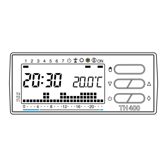
  • Seite 36 1 2 3 4 5 6 7 14 15 1 2 3 4 5 6 7 Abb. 1...
  • Seite 37 ANZEIGEN UND ÄUSSERE TASTEN TASTEN (siehe Abb. 1) Wahl der Betriebsart MANUELL oder AUTO- ANZEIGEN MATISCH des Gerätes. 1 0 ÷ 23 Stunden-Skala Verminderung (Tem- Programmgraphik. peratur, Tag, Uhrzeit, Der blinkende Cursor usw.). gibt die Uhrzeit an. Steigerung (Tempera- 2 T1÷T3 Temperaturbereiche. tur, Tag, Uhrzeit, usw.).
  • Seite 38 TH/400TX INHALTSVERZEICHNIS ELEKTRONISCHER- Kapitel Seite TEMPERATURREGLER 1 - Installation 2 - Einstellen der uhr 3 - Vorgespeicherte Programme 4 - Manueller Betrieb 5 - Individuelle Einstellung der Temperaturbereiche für das Heizprogramm 6 - Individuelle Einstellung der Temperaturbereiche für das Klimatisierungprogramm 44 7 - Individuelle Einstellung des Täglichen 8 - JOLLY-Programm...
  • Seite 39 THERMOPROGRAM variieren. Die Kodierung und ±0,1 °C bis ±0,9 °C eingestellt wer- TH400TX regelmäßige Wiederholung der den. Der Temperaturregler ist für die Funksignale gewährleistet Sicher- Steuerung von Heizungen und heit beim Betrieb auch in äußerst Der elektronische, programmier- Klimaanlagen verwendbar. funkgestörten Umgebungen.
  • Seite 40: Installation

    1 - INSTALLATION und anschließend mit der mitgelie- beschädigen. Sollten die Display- ferten Schraube fixieren (Abb.11). Anzeigen, innerhalb von 30 Installieren Sie das Gerät an einem • 3 alkalische Batterien LR03 Typ Sekunden, nicht erscheinen, die Ort, an dem die Raumtemperatur AAA zu 1,5 V unter Berücksichti- Resettaste R drücken (Abb.
  • Seite 41 Die Stundenziffern blinken. die Einstellung von Uhrzeit und 2.2 - Die Taste (Abb. 14) 2.5 - Die Taste oder Wochentag abzubrechen (Abb. 20). drücken. drücken, bis der gewünschte Wert Das Blinken der beiden Punkte zwi- Die Minutenziffern blinken. für die exakte Stunde erhalten ist schen Stunde und Minuten zeigt 2.3 - Die Taste oder...
  • Seite 42: Vorgespeicherte Programme

    Ziffern am Display um jeweils eine bereits ein Heizprogramm vorge- T3 28 °C Einheit vermindert oder gesteigert; sehen, dessen Temperaturverlauf Wenn die im Festspeicher enthalte- bei anhaltendem Drücken laufen von Montag bis Freitag (1÷5) der nen Programme Ihren Anforderun- Abb. 21, und am Samstag und die Ziffern des Displays während gen entsprechen, benötigt THERMO- Sonntag (6 und 7) der Abb.
  • Seite 43 beliebig nach oben oder unten einige Stunden oder Tage eingehal- drücken, bis die gewünschte verändert werden kann (das Gerät ten werden soll (zum Beispiel um Stundenzahl von 1 bis 99 erreicht wird mit einem voreingestellten bei überraschendem Besuch länger ist (Abb. 27). In der Stundenzahl Temperaturwert von 20 °C gelie- eine angenehme Temperatur ein- ist auch jene des Augenblicks der...
  • Seite 44: Individuelle Einstellung Der Temperaturbereiche Für Das Heizprogramm

    ten (das heißt der Rest des Tages tur wird der T1 zugeordnete ung der Temperaturbereiche wird der Programmierung wird als 1 Temperaturwert angezeigt (einge- durch das erneute Erscheinen der Tag gezählt). speicherter Wert 16 °C). gesamten Graphik des Tagespro- Anmerkung. Um vor Ablauf der 5.4 - Den für T1 gewünschten grammes am Display bestätigt.
  • Seite 45: Jolly-Programm

    7.2 - Den Tagesanzeiger mit der peraturbereich anwählen; durch beschrieben vorgehen (Abb. 41). Taste 1÷7 auf die Position 1 Drücken der Taste 0÷23 zur fol- 7.7 - Nach Abschluß der Pro- (Montag) stellen (Abb. 36). genden Stunde übergehen und grammierung kann durch Drücken 7.3 - Mit den Tasten 0÷23 ebenfalls die gewünschte Tem-...
  • Seite 46 Tages angewählt werden kann und Änderung durchführen, wie unter 1÷7 auf den gewünschten Tag stel- für den Rest des betreffenden den Absätzen 5, 6 und 7 (die Punkte len (Abb. 45). Tages aktiviert bleibt, oder auch für 7.2, 7.5 und 7.6 gelten hier nicht) 8.8 - Die Taste drücken (Abb.
  • Seite 47: Frostschutzbetrieb

    Löschen kann auch durch zweima- befindliche Segment bestätigt die kann die Funktion ZEITGEREGEL- liges Drücken der Taste erfol- durchgeführte Wahl. TER FROSTSCHUTZBETRIEB akti- Display erscheint viert werden. Nachdem die gewün- gen (Abb. 48). Mit der Taste Programm-Graphik und die zuvor schte Dauer eingestellt wurde, (Abb.
  • Seite 48: 10- Betriebszeit Der Anlage

    54) drücken, bis die gewünschte Programmierung in Tagen 10 - BETRIEBSZEIT Stundenzahl von 1 bis 99 erreicht 9.5 - Die Taste zweimal DER ANLAGE ist. In der Stundenzahl ist auch jene drücken (Abb. 56). THERMOPROGRAM ist mit einem des Augenblicks der Programmier- Anstelle der laufenden Uhrzeit er- Betriebsstundenzähler (bis 9.999) ung enthalten (das heißt der Rest...
  • Seite 49: Sichtbarmachung Der Werte Der Temperaturbereiche

    11 - SICHTBARMACHUNG in AUTOMATISCHEM Betrieb befin- bestätigt den Ausschluß von DER WERTE DER den. Bei Drücken der Taste oder THERMOPROGRAM TEMPERATURBEREICHE erscheinen am Display die Anlagensteuerung Temperaturwerte der entsprechen- Programm-Graphik verschwindet 11.1 - Die Geräteklappe öffnen. den Bereiche (Abb. 63). Eventuell (Abb.
  • Seite 50 ZEITGEREGELTER der Tageszahl ist auch jener der 12.6 - Die Taste oder drü- AUSSCHLUSS DER ANLAGE Programmierung enthalten (das heißt cken, bis die gewünschte Stunden- der Rest des Tages der Programmier- zahl von 1 bis 99 erreicht ist (Abb. Um die Anlage während einiger ung wird als 1 Tag gezählt).
  • Seite 51: 13- Reset

    13 - RESET MOPROGRAM wird mit einer drücken, bis der gewünschte Wert erreicht ist (Abb. 75). Voreinstellung des Wärmediffe- Funktionsanomalien, Eingriffe oder 14.5 - Durch erneutes Drücken der rentials von ±0,2 °C geliefert. andere technische Gründe können Taste T von der Programmierung ab- Dieser thermische Einschaltinter- das Reset des Gerätes erforderlich springen, oder zu diesem Zweck 10 s.
  • Seite 52: Die Geräteklappe Öffnen

    15.1 - Die Geräteklappe öffnen 16 - TECHNISCHE DATEN • Möglichkeit der Zeitregelung des (Abb. 77). manuellen Betriebs, der Frost- Gerät für zivile Zwecke. schutzfunktion und des Anlagen- 15.2 - Den Batteriedeckel abneh- Sender ausschlusses (in Stunden und men (Abb. 78). •...
  • Seite 53 TH400RX INHALTSVERZEICHNIS EMPFANGSGERÄT Kapitel Seite MIT 1 KANAL 1 - Aufstellung 2 - Installation 3 - Elektrische Anschlüsse 4 - Programmierung 5 - Technische Daten...
  • Seite 54: Aufstellung

    1 - AUFSTELLUNG Das Empfangsgerät TH400RX (mit 1 Kanal) kann in der Nähe des zu steuernden Geräts (z.Bsp. elektrisch gesteuertes Ventil, gesteuertes Ventil, Ventilkonvektor) installiert werden. Falls das Empfangsgerät in Räumen mit schlechtem Empfang aufzustellen ist, ist anstelle der mit- gelieferten Antenne auf dem Fre- quenzbereich von 430 MHz der Anschluß...
  • Seite 55: Programmierung

    TH/400 RX TH/400 RX BELASTUNG BELASTUNG OFFEN GESCHLOSS Abb. 2 Abb. 3 Schema der Abb. 2 oder 3 befolgen. Elektroventil, usw. L = Phasenleiter ANMERKUNG. Für den Stromnetz- U2 = motorisiertes Ventil Relaiskontakte anschluß des Empfangsgeräts ist C = gemeinsamer Leiter 4 - PROGRAMMIERUNG eine geeignete Trennvorrichtung NA = normalerweise offener Kontakt...
  • Seite 56: Technische Daten

    des Übertragungsgeräts oder einen, 4.2 - Notzustand diese Weise eine angenehme Tem- Falls Übertragungsgerät peratur bei. aus einem anderen Grund, unerfolg- TH400TX defekt sein oder aus ten Empfang des Steuerbefehls von 5 - TECHNISCHE DATEN einem anderen Grunde der Emp- über 15 min vorzubeugen.
  • Seite 57 TH404RX INHALTSVERZEICHNIS EMPFANGSGERÄT Kapitel Seite MIT 4 KANÄLEN 1 - Aufstellung 2 - Installation 3 - Elektrische Anschlüsse 4 - Programmierung 5 - Technische Daten...
  • Seite 58: Aufstellung

    1 - AUFSTELLUNG Das Empfangsgerät TH404RX (mit 4 Kanälen) kann in der Nähe der zu steuernden Geräte (z.Bsp. elektrisch gesteuertes Ventil, gesteuerte Ventile) installiert werden. Falls das Empfangsgerät in Räumen mit schlechtem Empfang aufzustel- len ist, ist anstelle der mitgelieferten Antenne auf dem Frequenzbereich von 430 MHz der Anschluß...
  • Seite 59: Programmierung

    TH/404 RX TH/404 RX BELASTUNG BELASTUNG OFFEN GESCHLOSS BELASTUNG BELASTUNG OFFEN GESCHLOSS Abb. 2 Abb. 3 Schema der Abb. 2 oder 3 befolgen. L = Phasenleiter Elektroventil, usw. ANMERKUNG. Für den Stromnetz- U2 = motorisiertes Ventil Relaiskontakte anschluß des Empfangsgeräts ist C = gemeinsamer Leiter 4 - PROGRAMMIERUNG eine geeignete Trennvorrichtung...
  • Seite 60 des Übertragungsgeräts oder einen, Wartung der Anlage zu erleichtern. 4.2 - Notzustand aus einem anderen Grund, unerfolg- Das Empfangsgerät ist mit einer Falls Übertragungsgerät ten Empfang des Steuerbefehls von dreifarbigen LED 2 versehen, die TH400TX defekt sein oder aus über 15 Minuten vorzubeugen. die Stufe des Frequenzbereichs einem anderen Grunde der Emp- ANMERKUNG.
  • Seite 61: Allgemeine Garantiebedingungen

    alle 15 min ein und aus und behält ALLGEMEINE auf diese Weise eine angenehme GARANTIEBEDINGUNGEN Temperatur bei. Der Vertriebshändler vor Ort ist 5 - TECHNISCHE DATEN unter Beachtung der geltenden Landesgesetze für die Produkt- Gerät für zivile Zwecke. garantie zuständig. •...
  • Seite 62: Instructions Pour L'installateur

    Félicitations pour l'achat de votre INSTRUCTIONS POUR ELIMINATION thermostat TH400TX-RX L'INSTALLATEUR TH402TX-RX. S'assurer que le matériel d’embal- Pour obtenir les prestations maxi- • Lire attentivement les instruc- lage n’est pas abandonné dans la males de votre appareil et pour tions contenues dans le document nature qu’il...
  • Seite 63 Le Thermoprogram TH400TX-RX Le récepteur TH400RX se consti- Le Thermoprogram TH402TX-RX se compose d’1 thermostat tue de: se compose de 2 thermostats TH400TX d’1 récepteur TH400TX d’1 récepteur TH400RX. 1 support mobile muni de TH404RX. 2 cache-bornes et de rail DIN Le récepteur TH400TX se consti-...
  • Seite 64 Le récepteur TH404RX se consti- tue de: 1 support mobile muni de 2 cache-bornes et de rail DIN 1 antenne (câble unipolaire de 18...
  • Seite 65 INSTRUCTIONS TH400TX INSTRUCTIONS TH400RX INSTRUCTIONS TH404RX...
  • Seite 66 1 2 3 4 5 6 7 14 15 1 2 3 4 5 6 7 Fig. 1...
  • Seite 67 INDICATIONS ET Installation en fonc- COMMANDES EXTERNES tion. (Voir fig. 1) Tranche horaires d'acti- vation de l'installation. INDICATIONS Rouge = confort Bleu = épargne 1 0 ÷ 23 Echelle horaire dans le graphique du program- COMMANDES Le curseur clignotant Sélection de mode indique l'heure qui cor- Fig.
  • Seite 68 TH400TX INDEX 15- Remplacement des batteries d'alimentation Chapitre Page THERMOSTAT 16- Caractéristiques ELECTRONIQUE 1 - Installation techniques PROGRAMMABLE - Conditions générales 2 - Mise au point de l'horloge 70 de garantie 3 - Programmes prémémorisés 4 - Fonctionnement manuel 5 - Personnalisation de la valeur des niveaux de température pour le programme de chauffage 74...
  • Seite 69 THERMOPROGRAM pourra varier en fonction de la TH400TX structure du bâtiment. Le codage des commandes et leur répétition périodique garantissent la sécurité thermostat programmable du fonctionnement, même dans THERMOPROGRAM TH400TX a des locaux très perturbés. été étudié pour garantir des condi- La technologie choisie pour l’émet- tions de température idéales tout teur et le récepteur répond aux...
  • Seite 70 1 - INSTALLATION • Insérer 3 batteries-stylo alcali- appuyer sur la touche de reset R nes LR03, type AAA, de 1,5 V cha- (fig. 72). Lorsque ces opérations Prévoir l'installation de l'appareil cune dans leur propre logement en ont été correctement effectuées dans la position voulue pour qu'il respectant les polarités indiquées l'écran affiche les indications...
  • Seite 71 2.3 - Presser le bouton-poussoir Les deux points entre les heures et ou bien jusqu'à l'obtention ou bien jusqu'à l'obtention les minutes clignoteront pour con- de l'heure exacte (fig. 17). de la valeur exacte des minutes firmer la conclusion de l'opération. 2.6 - Presser le bouton-poussoir (fig.
  • Seite 72: Programme De Chauffage

    ou augmentent d'une unité; si les Les niveaux de température fixés instruction: il est prêt à fonctionner immédiatement et ponctuellement. boutons-poussoirs sont mainte- sont les suivants: Pour la création de programmes nus presses les chiffres sur l'écran T1 16 °C personnalisés suivre les indications T2 18 °C défilent lentement pendant les 5...
  • Seite 73 fonctionnement MANUEL en pres- on peut sélectionner une tempéra- 4.2 - Fixer la valeur de la tempé- ture quelconque entre 2 °C et 35 rature souhaitée en pressant le sant le bouton-poussoir (fig. °C qui sera maintenue constante bouton-poussoir ou bien 24).
  • Seite 74 également celui au cours duquel soit actif et agir éventuellement sur le que niveau de T est limitée par les est effectuée la programination (le bouton-poussoir (fig. 32). valeurs du niveau immédiatement résidu du jour au cours duquel 5.3 - Presser le bouton-poussoir supérieur et inférieur, c'est-à-dire s'effectue l'opération est donc T (fig.
  • Seite 75 Quoi qu'il en soit, 10 s après la der- 7 - PERSONNALISATION DU b) L'indication de la température nière manoeuvre, l'appareil quitte la PROGRAMME QUOTIDIEN adopte la valeur du niveau sélec- procédure en considérant valables DES TEMPERATURES tionné dans l'heure indiquée par le les données fixées jusqu'alors.
  • Seite 76 procedure que celle indiquée au semaine, les congés, etc...) qui firme le démarrage du programme. point 7.4 (fig. 41). peut être démarré à tout moment 8.3 - Effectuer la personnalisa- 7.7 - Lorsque la programmation de la journée en cours et qui tion éventuelle comme décrit dans est terminée on peut retourner demeure actif pendant la partie...
  • Seite 77 8.7 - A l'aide du bouton-poussoir ment effectué en pressant deux Le segment sous le symbole 1÷7 porter l'indicateur vis-à-vis du fois le bouton-poussoir (fig. confirme le choix effectué. jour choisi (fig. 45). 48). Pour revenir au fonctionne- Le graphique du programme 8.8 - Presser le bouton-poussoir ment AUTOMATIQUE et au jour en disparalt sur l'écran qui af fiche la...
  • Seite 78 l'appareil revient au fonctionne- (le résidu de l'heure au cours de grammation (le résidu du jour au ment AUTOMATIQUE. laquelle l'opération s'effectue est cours duquel s'effectue l'opération 9.2 - Presser une seule fois le bou- donc compté comme 1 heure). est donc compté...
  • Seite 79 bouton-poussoir C (fig. 60). est affichée la valeur de la tempé- 12 - EXCLUSION DE rature attribuée à T1. Le temps de fonctionnement est L'INSTALLATION 11.3 - Presser à nouveau le bou- affiché sur l'écran pendant 5 ton-poussoir T (fig. 62) pour passer Cette position est utile durant les secondes.
  • Seite 80 Avec le programme RAFRAICHIS- Avec le programme CHAUFFAGE: Le comptage des heures com- SEMENT: 12.4 - Presser deux fois le bouton- prend également celle dans laquel- 12.2 - Presser une seule fois le poussoir (fig. 66). le s'effectue la programmation (le bouton-poussoir Le segment actif sous confir-...
  • Seite 81 99 (fig. 70). Le comptage des jours 13 - RESET des installations avec des radia- comprend également celui au teurs en fonte. Des anomalies de fonctionnement, cours duquel est effectuée la pro- Si les caractéristiques de l'installa- des interventions et d'autres tion exigent de modifier cette valeur, grammation (le résidu du jour au motifs techniques peuvent exiger...
  • Seite 82: Batteries D'alimentation

    14.6 - Fermer la porte de l'appareil. 15.2 - Extraire le couvercle des L'utilisation de batteries épui- batteries (fig. 78). sées peut provoquer des anoma- 15 - REMPLACEMENT DES Les indications sur l'écran dispa- lies de fonctionnement. BATTERIES D'ALIMENTATION raissent. Agir, dans ce cas, conformément Le message sur l'afficheur...
  • Seite 83 • Ecran graphique LCD. • Plage de réglage: de +2 °C à +35 • Température de fonctionnement: • Alimentation: 3 batteries-stylo °C. de 0 °C à +40 °C. alcalines LR03, type AAA, de 1,5 • Niveaux des températures: trois, • Dimensions: 116x80x21 mm. V chacune.
  • Seite 85 TH400RX INDEX RECEPTEUR A 1 CANAL Chapitre Page 1 - Emplacement 2 - Installation 3 - Connexions électriques 86 4 - Programmation 5 - Caractéristiques techniques...
  • Seite 86: Emplacement

    1 - EMPLACEMENT Le récepteur TH400RX (à 1 canal) peut être installé à proximité de l’ap- pareil qu'il doit commander (par ex. soupape électrique, soupape moto- risée, convecteur). Si le récepteur est installé dans un local où la réception est difficile, dans tel cas il est indispensable de raccorder à...
  • Seite 87 TH/400 RX TH/400 RX CHARGE CHARGE OUVRE FERME Fig. 2 Fig. 3 NOTA. Pour la connexion du récep- L = phase soupape électrique, etc. teur au secteur, prévoir un disposi- U2 = soupape motorisée. Conducteurs du relais tif de coupure adéquat. C = commun 4 - PROGRAMMATION NC = contact normalement fermé...
  • Seite 88 tat du relais au cas où l’émetteur ne pas ou si, pour une raison quel- 5 - CARACTERISTIQUES ne fonctionnerait pas ou que, pour conque, la commande n'est pas TECHNIQUES toute autre raison, la commande reçue pendant plus de 15 min, il est Appareil à...
  • Seite 89 TH404RX INDEX RECEPTEUR A 4 CANAUX Chapitre Page 1 - Emplacement 2 - Installation 3 - Connexions électriques 90 4 - Programmation 5 - Caractéristiques techniques...
  • Seite 90 1 - EMPLACEMENT Le récepteur TH404RX (à 4 canaux) peut être installé à proxi- mité des appareils qu'il doit com- mander (par ex. soupapes électri- ques, soupapes motorisées, etc.). Si le récepteur est installé dans un local où la réception est difficile, dans tel cas il est indispensable de raccorder à...
  • Seite 91 TH/404 RX TH/404 RX CHARGE CHARGE OUVRE FERME CHARGE CHARGE OUVRE FERME Fig. 2 Fig. 3 LEGENDE NC = contact normalement fermé commandé par le thermostat. NA = contact normalement ouvert Conducteurs d’alimentation du Suivre donc soit le schéma de la fig.
  • Seite 92 4 - PROGRAMMATION NOTA. S’il existe plusieurs Déplacer le cavalier dans la posi- TH400TX, il est recommandé de tion souhaitée pour la condition En cours d’installation, il est numéroter l’émetteur selon la d'urgence (O, S ou bien C). nécessaire de mémoriser les codes séquence de mémorisation du 4.2 - Condition d’urgence des émetteurs et de sélectionner...
  • Seite 93 • Cavalier sur C (confort): l’instal- lation se met en marche et s’arrête toutes les 15 min, en maintenant ainsi une température confortable. 5 - CARACTERISTIQUES TECHNIQUES Appareil à usage civil. • Alimentation: 230Vca, 50/60 Hz. • Puissance absorbée: 2VA. •...
  • Seite 94: Conditions Générales De Garantie

    CONDITIONS GÉNÉRALES DE GARANTIE La garantie sur le produit sera fournie par le distributeur local conformément aux lois en vigueur dans le pays.
  • Seite 96 BPT S.p.A. 30020 Cinto Caomaggiore-VE-Italy Via Roma, 41 http: www.bpt.it/e-mail: info@bpt.it...

Diese Anleitung auch für:

Th402tx-rx

Inhaltsverzeichnis