Herunterladen Inhalt Inhalt Diese Seite drucken
Bpt TH 125 Gebrauchsanweisung

Bpt TH 125 Gebrauchsanweisung

Programmierbarer raumthermostat thermoprogram
Inhaltsverzeichnis

Werbung

Verfügbare Sprachen

Verfügbare Sprachen

PROGRAMMABLE
GB
THERMOSTAT
THERMOPROGRAM
PROGRAMMIERBARER
D
RAUMTHERMOSTAT
THERMOPROGRAM
THERMOSTAT
F
PROGRAMMABLE
THERMOPROGRAM
+15
P
R
°C
°C
24
24
22
28
22
28
20
26
20
26
18
24
18
24
15
22
15
22
6
18
6
18
0
3
6
9
12
TH 125
20
26
18
24
22
15
22
28
6
24
18
°C
°C
24
24
22
28
22
28
20
26
20
26
18
24
18
24
15
22
15
22
6
18
6
18
15
18
21
INSTRUCTIONS
FOR USE
GEBRAUCHS-
ANWEISUNG
MODE
D'EMPLOI

Werbung

Inhaltsverzeichnis
loading

Inhaltszusammenfassung für Bpt TH 125

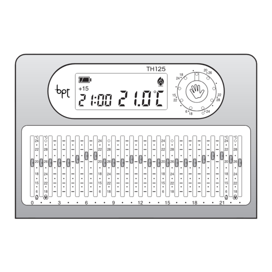
  • Seite 1 PROGRAMMABLE TH 125 THERMOSTAT THERMOPROGRAM PROGRAMMIERBARER RAUMTHERMOSTAT THERMOPROGRAM THERMOSTAT PROGRAMMABLE THERMOPROGRAM INSTRUCTIONS FOR USE GEBRAUCHS- °C °C °C °C ANWEISUNG MODE D’EMPLOI...
  • Seite 2 Congratulations on your purchase of the RECOMMENDATIONS THERMOPROGRAM TH125 thermostat. FOR THE INSTALLER TH125 To get the most out of your thermostat, exploiting its features and functions to the • Read the contents of the following pages The TH125 THERMOPROGRAM program- full, we suggest you read this manual care- with care because they provide important mable thermostat is designed to ensure ideal...
  • Seite 3 DISPOSAL Do not litter the environment with packing material: make sure it is disposed of accord- ing to the regulations in force in the country where the product is used. When the equipment reaches the end of its life cycle, take measures to ensure it is not discarded in the environment.
  • Seite 4 12 13 14 15 +15 +30 +45 °C °C °C °C Fig. 1...
  • Seite 5: Indications And Controls

    INDICATIONS AND CONTROLS Cooling program indicator. Increase (temperature, day, (see fig. 1) time, etc.). Heating program indicator. Decrease (temperature, day, Sensor push button for cover time, etc.). Digital thermometer. closing. 21 6÷24°C Temperature range for heating Button for selecting MANUAL Reset.
  • Seite 6: Inhaltsverzeichnis

    CONTENTS 25 18÷31°C Temperature range for heating 13 -Viewing the programmed program ( temperatures Chapter Page A position which exceeds 31 14 -Setting of on-off time delays °C (O) places the system in 1 - Location OFF status. 15 -Remote control 2 - Installation 16 -Replacing the batteries 3 - Power supply...
  • Seite 7: Location

    1 - LOCATION To fix the base to the wall (fig. 7) use the spacer and the two screws with inserts, all Install the unit on an internal wall (fig. 2) in provided. a position which is suitable for correct mea- WARNING.
  • Seite 8: Power Supply

    Fig. 6 LOAD LOAD CLOSED OPEN Fig. 8 Fig. 9 N = neutral Loads U1 = burner, circulation pump, solenoid Relay contacts valve etc. NC= normally closed contact U2 = motorized valve C = common NA = normally open contact 3 - POWER SUPPLY Inputs for remote control Insert the three AAA 1.5 V LR03 penlight...
  • Seite 9 Fig. 13 Fig. 12 of the housing (fig. 10). 4 - THERMAL THRESHOLD WARNING. Inserting the batteries the The temperature differential can be set from wrong way can damage the unit. ±0.1 °C to ±0.9 °C. Fig. 10 If the messages on the display do not THERMOPROGRAM is supplied factory set appear within 30 seconds, press the reset for operation with a temperature differential...
  • Seite 10: Setting The Clock

    Fig. 14 Fig. 15 Fig. 17 After approximately 10 s, or if you press the button, the display will show the time and room temperature again. Note. When reset button R is pressed, the temperature differential returns to the ±0.2 °C default setting.
  • Seite 11: Automatic Program

    Fig. 19 Fig. 21 Fig. 23 °C Fig. 20 Fig. 22 Fig. 24 OFF in the temperature field. The indication 7 - AUTOMATIC PROGRAM cursor and its position (fig. 23). is animated when the cooling system is You can change programming at any time by When the machine is started, it sets up in in operation.
  • Seite 12: Manual Program

    Fig. 25 Fig. 26 Fig. 28 8 - MANUAL PROGRAM 8.1 - To change over from AUTOMATIC to MANUAL operating mode, press the button (fig. 24) (the indication on the display shows the choice you have made). 8.2 - Use the knob (fig.
  • Seite 13: 10 -Stand-By Mode In Heating Program

    Fig. 30 Fig. 32 Fig. 33 9.5 - Press the button twice (fig. 31). The message d01 comes up on the display in place of the current time. 9.6 - Press the button (fig. 32) until you reach the desired number of days, which can range from 1 to 99.
  • Seite 14: 11 -Stand-By Mode In Cooling Program

    Fig. 35 Fig. 36 Fig. 37 freeze temperature, which can be changed 11 - STAND-BY MODE IN COOLING with the button (fig. 35). PROGRAM Any temperature can be chosen between 2 11.1 - Press the button once (fig. 37). °C and 35 °C, and it will be maintained until The message OFF confirms that THERMO- further adjustments are made or until a dif- PROGRAM control of the system is bypas-...
  • Seite 15 Fig. 39 Fig. 40 Fig. 42 The countdown of the hours also includes Note. To return to AUTOMATIC mode before the hour in which programming is carried the programmed time is up, press the out (hence, the remainder of the hour in 13 - WIEWING THE PROGRAMMED which the setting is made counts as a whole TEMPERATURES...
  • Seite 16: 14 -Setting Of On-Off Time Delays

    Fig. 43 Fig. 45 Fig. 47 system at 6:30. To do so, place cursor 6 at the comfortable temperature and set a time delay of 30 min. The THERMOPROGRAM will start at 6.30, maintaining until then the temperature set by cursor 5. The indication of the inserted delay is shown in automatic mode during the hour in which the delay has been programmed.
  • Seite 17: 16 -Replacing The Batteries

    Fig. 48 Fig. 50 Fig. 52 On the display, instead of the current time, the message h01 will appear if you are set- ting the hours, or d01 if you are setting the days. 15.4 - Press button until you reach the desired hours (fig.
  • Seite 18 Fig. 53 Fig. 55 Fig. 56 16.2 - Insert three AAA 1.5 V LR03 penlight seconds the indications on the display will batteries, new and of the same type, adhe- re-appear. ring to the polarity indicated on the bottom If the messages on the display do not Fig.
  • Seite 19: 18 -Cover Replacement

    WARNING. Clean the cover only with a soft cloth dampened with water. 19 - TECHNICAL FEATURES Unit for domestic and commercial use. • Independently installed electronic device. • LCD graphic display. • Power supply: three penlight AAA 1.5 V LR03 alkaline batteries. •...
  • Seite 20 • Dimensions: 139x26x94 mm. Fig. 60 • Thermal differential: adjustable from ± 0.1 °C to ± 0.9 °C. • Reading resolution: 01 °C. • Displayed field of reading: from 0 °C to +40 °C. • Precision: ≤±0,3 °C. • Class A software. •...
  • Seite 21: General Guarantee Terms

    GENERAL GUARANTEE TERMS The guarantee on the product will be provi- ded by national BPT distributor or by local dealer, according to the laws in force in the Country.
  • Seite 22 Wir beglückwünschen Sie zur Wahl des HINWEISE FÜR DEN THERMOPROGRAM Raumthermostaten TH125. INSTALLATEUR TH125 Für beste Leistungen und die korrekte Kenntnis der Merkmale und Funktionen • Lesen Sie die in diesem Heft gegebenen Der programmierbare Thermostat THERMO- Ihres Thermostaten sollten Sie diese Anweisungen sorgfältig durch, weil diese PROGRAM TH125 wurde so konzipiert, dass Gebrauchsanweisung sorgfältig durchlesen...
  • Seite 23: Entsorgung

    ENTSORGUNG Vergewissern sich, dass Verpackungsmaterial gemäß den Vorschrif- ten des Bestimmungslandes ordungsgemäß und umweltgerecht entsorgt wird. Das nicht mehr benutzbare Gerät ist umwelt- gerecht zu entsorgen. Die Entsorgung hat den geltenden Vorschrif- ten zu entsprechen und vorzugsweise das Recycling der Geräteteile vorzusehen. Die wiederverwertbaren Geräteteile sind mit einem Materialsymbol und –zeichen verse- hen.
  • Seite 24 12 13 14 15 +15 +30 +45 °C °C °C °C Abb. 1...
  • Seite 25 HINWEISE UND STEUERFUNKTIONEN Anzeige für Anlage Einschalttaste für MANUEL- (Abb. 1) MANUELLEM Betrieb. LES, ZEITGEREGELTES PRO- GRAMM oder ZEITGERE- Sensortaste für die Schließung Anzeige des Klimatisierungs- GELTEN ANLAGENAUS- der Abdeckklappe. programms. SCHLUSS. Reset. Zunahme (Temperatur, Tag, Anzeige des Heizprogramms. Uhrzeit, usw.). Taste für die Sichtanzeige der Digital-thermometer.
  • Seite 26 INHALTSVERZEICHNIS 24 6÷24 °C Temperatur-Skala für 12 -Zeitgeregelter Anlagenausschluss Heizprogramm ( Kapitel 13 -Sichtbarmachung der 25 18÷31 °C Temperatur-Skala für programmierten Temperaturen 1 - Installationsort Klimatisierungsprogramm ). Die Position von über 14 -Einstellung der verzögerten 2 - Installation 31 °C (O) schaltet die Anlage Ein- und Ausschaltung der Anlage 36 auf OFF.
  • Seite 27: Installationsort

    1 - INSTALLATIONSORT Rundkasten (Abb. 6) den mitgelieferten Abstandshalter einsetzen. Installieren Sie das Gerät an einer Für die Bodenbefestigung an der Wand Innenwand (Abb. 2) und an einer Stelle, an (Abb. 7) den Abstandshalter und die beiden der die Raumtemperatur korrekt gemessen zum Lieferumfang gehörenden Schrauben werden kann;...
  • Seite 28 Abb. 6 BELASTUNG BELASTUNG GESCHLOSSEN OFFEN Abb. 8 Abb. 9 Klemmendeckel wieder befestigen. NA = normalerweise offener Kontakt LEGENDE Eingänge für Fernsteuerung Netzleiter 1 Eingang L = Phasenleiter 2 Eingang N = Nullleiter Belastungen Relaiskontakte U1 = Brenner, Umwälzpumpe, Elektroventil, NC = normalerweise geschlossener Kontakt usw.
  • Seite 29: Versorgung

    Abb. 13 Abb. 12 3 - VERSORGUNG ACHTUNG. Öffnung Gerätklappe ist diese bei abgeschlossenen Drei neue, gleiche Mignon - Alkalibatterien Einstellungen erneut korrekt zu schließen, LR03 Typ AAA zu 1,5 V unter Berücksichtig- Abb. 10 um einem unnützen Batterieverbrauch zu ung der Polaritätsmarkierungen am Boden vermeiden (Abb.
  • Seite 30: Einstellen Der Uhr

    Abb. 14 Abb. 16 Abb. 18 Abb. 15 Abb. 17 Abb. 19 Am Display erscheint die Aufschrift d 0.2 °C, wird, stellt sich das Wärmedifferential auf Bei jedem Drücken der Taste oder die zirka 10 s lang sichtbar bleibt. ±0,2 °C ein. werden die Displayziffern um jeweils eine 4.2 - Taste (zurück) oder...
  • Seite 31: Heiz- Und

    °C Abb. 20 Abb. 21 Abb. 22 °C. Über 31 °C wird die Anlagenausschal- drücken, bis die genaue Uhrzeit erreicht ist. tung bedient, die durch die Einschaltung der 5.5 - Die Taste drücken, um die Anzeige OFF im Temperaturbereich ange- Einstellung zu beenden (Abb.
  • Seite 32: Manueller Betrieb

    Abb. 24 Abb. 25 Abb. 26 ACHTUNG. Die Temperaturanzeige ist nur che den AUTOMATISCHEN Betrieb wie- bei offener Klappe möglich. Falls eine derherstellt. Betätigung der Cursoren nicht notwendig 9 - MANUELLES, ZEITGEREGELTES ist, sollte die Klappe zur Vermeidung eines PROGRAMM unnützen Batterieverbrauchs geschlossen werden.
  • Seite 33 Abb. 28 Abb. 30 Abb. 32 Abb. 29 Abb. 31 Abb. 33 Programmierung vorgenommen wird (die über den Drehknopf die gewünschte die Programmierung vorgenommen wird restliche Stunde, in der die Operation erfolgt, Temperatur einstellen (Abb. 30). (der restliche Tag, an dem die Operation wird als 1 volle Stunde gezählt).
  • Seite 34: 10 -Anlagenausschluss Im Heizprogramm

    Abb. 34 Abb. 36 Abb. 37 Mit Frostschutz Die Anzeige der Raumtemperatur schaltet 10.1 - Die Taste nur einmal drücken sich für 5 s aus und es erscheint (Abb. 34). 10.3 - Zur Wiederherstellung des AUTOMA- Die Anzeige OFF bestätigt die getätigte Wahl. TISCHEN Betriebs die Taste drücken.
  • Seite 35 Abb. 38 Abb. 40 Abb. 41 Programmierung in Tagen Anstelle der laufenden Uhrzeit erscheint am 12.4 - Sicherstellen, dass der Thermostat Display die Aufschrift h01. auf den Anlagenausschluss (mit oder ohne Die Anzeige der Raumtemperatur schaltet Frostschutz) geschaltet wurde. sich für 5 s aus und es wird oder die 12.5 - Die Taste zweimal drücken (Abb.
  • Seite 36: 13 -Sichtbarmachung Der Programmierten Temperaturen

    Abb. 42 Abb. 43 Abb. 44 den AUTOMATISCHEN Betrieb. Falls die Taste im manuellen Betrieb oder bei Anmerkung. Um vor Ablauf der program- Anlagenausschluss betätigt wird, wird die mierten Zeit zum AUTOMATISCHEN Betrieb jeweils eingestellte Temperatur angezeigt. Die Einstellung der manuellen Temperatur zurückzukehren, die Taste drücken.
  • Seite 37: Fernsteuerung

    Abb. 46 Abb. 47 Abb. 48 In diesem Fall wird der Cursor 6 auf die Ablauf desselben der THERMOPROGRAM in Komforttemperatur und eine Verzögerung den Voraktivierungsstand zurückkehren, von 30 min eingestellt. THERMOPROGRAM sofern keine Operationen vorgenommen wird sich um 6.30 Uhr einschalten und bis werden.
  • Seite 38: 16 -Wechseln Der Batterien

    Abb. 51 Abb. 53 Abb. 55 Monats gewechselt werden müssen (Abb. 52). Wenn auf dem Display die Anzeige und das Symbol erscheinen, ist Abb. 52 Abb. 54 das Gerät nicht mehr in Betrieb und hat die Klimaanlage auf OFF geschaltet (Abb. 53). Tageszahl (Abb.
  • Seite 39 Abb. 57 Abb. 56 Abb. 58 den alle Anzeigen des Displays. Zur Neueinschaltung des Geräts ist ab 16.2 - Drei neue, gleiche Mignon Kapitel 4 vorzugehen. Alkalibatterien LR03 Typ AAA zu 1,5 V unter Das Gerät an den Punkten ansetzend wieder Berücksichtigung der Polaritätsmarkierun- verschließen (Abb.
  • Seite 40: 17 -Funktionsstörungen Des Gerätes

    17 - FUNKTIONSSTÖRUNGEN DES • Regelbereich bei Klimatisierungsbetrieb: GERÄTES von 18 bis 31 °C. • Drei Betriebsarten: MANUELL, AUTOMA- Im Falle von Funktionsstörungen die TISCH, AUSSCHLUSS DER ANLAGE. Resettaste R drücken (Abb. 54). • Wählbare Programme: HEIZUNG, KLIMA- Bei diesem Vorgang gehen die Einstellungen TISIERUNG.
  • Seite 41: Allgemeine Garantiebedingungen

    ALLGEMEINE GARANTIEBEDINGUNGEN Der Vertriebshändler vor Ort ist unter Beachtung der geltenden Landesgesetze für die Produktgarantie zuständig.
  • Seite 42: Instructions Pour L'installateur

    Le thermostat programmable THERMOPRO- et d'exploiter au mieux les caractéristiques • Lire attentivement les instructions conte- GRAM TH 125 a été conçu pour garantir des et les fonctions de votre thermostat, lire nues dans la présente notice car elles four- conditions de température idéales tout au...
  • Seite 43 ELIMINATION S'assurer que le matériel d’emballage n’est pas abandonné dans la nature et qu’il est éliminé conformément aux normes en vigueur dans le pays d'utilisation du produit. À la fin du cycle de vie de l'appareil, faire en sorte qu'il ne soit pas abandonné dans la nature.
  • Seite 44 12 13 14 15 +15 +30 +45 °C °C °C °C Fig. 1...
  • Seite 45 SIGNALISATIONS ET COMMANDES Indicateur de fonctionnement Touche de mise en marche du (fig. 1) en MANUEL. PROGRAMME MANUEL TEM- PORISE ou d'EXCLUSION TEM- Bouton-poussoir pour Indicateur du programme de PORISEE DE L'INSTALLATION. fermeture du volet. rafraîchissement. Augmentation (température, Reset. Indicateur du programme de jour, heures, etc.).
  • Seite 46 SOMMAIRE 24 6÷24°C Echelle de température pour le 12- Exclusion temporisée programme de chauffage ( de l'installation Chapitre Page. 25 18÷31°C Echelle de température pour 13- Visualisation des températures 1 - Positionnement programme de rafraîchisse- programmées ment d'air ( 2 - Installation Une position supérieure à...
  • Seite 47: Positionnement

    1 - POSITIONNEMENT 6) utiliser la douille fournie. Pour fixer le fond au mur (fig. 7) utiliser la douille, les Installer l'appareil sur un mur intérieur (fig. deux vis et les chevilles fournies. 2), dans une position permettant de relever ATTENTION.
  • Seite 48 Fig. 6 CHARGE CHARGE FERME OUVRE Fig. 8 Fig. 9 LEGENDE Entrées pour commande à distance Conducteurs d'alimentation du réseau 1 entrée électrique 2 entrée L = phase N = neutre Charges U1 = brûleur, pompe de circulation, électro- Contacts du relais vanne, etc.
  • Seite 49: Alimentation

    Fig. 13 Fig. 12 3 - ALIMENTATION tion de l'état de la pile s'affichent sur l'écran. ATTENTION. Chaque fois que le volet de l'ap- Placer trois piles alcalines LR03 type AAA de pareil est ouvert, il faudra le refermer cor- 1,5 V, neuves et du même type, en respec- Fig.
  • Seite 50: Mise Au Point De L'horloge

    Fig. 14 Fig. 15 Fig. 17 4.1 - Presser deux fois la touche (fig. 13). L'écran affiche le message d 0.2° C pendant environ 10 s. 4.2 - Presser la touche (arrière) o (avant) (fig. 14) jusqu'à obtenir la valeur souhaitée.
  • Seite 51: Programme De Chauffage Ou

    °C Fig. 20 Fig. 22 Fig. 23 quement de cette procédure et mémorisera sont de 6 °C à 24 °C. les dernières données programmées. L'indication s'affiche lorsque le système de rafraîchissement est en fonction. 6 - PROGRAMME DEI CHAUFFAGE OU DE RAFRAICHISSEMENT 7 - FONCTIONNEMENT En pressant la touche ( ) (fig.
  • Seite 52: Fonctionnement Manuel

    Fig. 24 Fig. 25 Fig. 27 moment, en déplaçant tout simplement les curseurs vers la position désirée. ATTENTION. La visualisation des tempéra- tures n'est possible que lorsque le volet est ouvert, il faut donc le fermer lorsqu'on n'a pas à intervenir sur les curseurs, de façon à...
  • Seite 53 Fig. 29 Fig. 31 Fig. 32 compris entre 1 et 99. Le calcul des heures prend également en compte l'heure où la programmation a été effectuée (par consé- quent le reste de l'heure à laquelle a été effec- tué l'opération sera compté comme 1 heure). Note.
  • Seite 54: 10- Exclusion De L'installation En

    Fig. 34 Fig. 36 Fig. 37 Avec protection antigel L'indication OFF confirme l'exclusion de 10.1 - Presser une seule fois la touche THERMOPROGRAM du contrôle du systè- (fig. 34). L'indication OFF confirme la sélection effectuée. L'indication de la température ambiante La température antigel programmée précé- disparaît pendant 5 s et s'affiche.
  • Seite 55 Fig. 38 Fig. 40 Fig. 41 grammé pour l'exclusion du système (avec Note. Pour revenir au mode AUTOMATIQUE ou sans antigel). avant la fin du temps programmé, presser la 12.2 - Presser une seule fois la touche touche (fig. 38). Sur l'écran, à...
  • Seite 56: 13- Visualisation Des Températures

    Fig. 42 Fig. 44 Fig. 45 13 - VISUALISATION DES 14 - PROGRAMMATION DU TEMPERATURES PROGRAMMEES RETARDEMENT DE LA MISE EN MARCHE ET DE L'ARRET DU 13.1 - Presser la touche (fig. 42). SYSTEME La température programmée pour l'heure indiquée s'affiche pendant 10 s sur le Il est possible de retarder de 15, 30, 45 min, display.
  • Seite 57: Commande A Distance

    Fig. 46 Fig. 47 Fig. 48 programmation effectuée. Si, par exemple, 15 - COMMANDE A DISTANCE vous souhaitez avoir une température agréa- En connectant une interface spéciale aux ble à 7:00, vous pouvez activer le système à bornes 1-2 (fig. 8 ou 9) il est possible d'ac- 6:30.
  • Seite 58: 16- Remplacement Des Piles D'alimentation

    Fig. 50 Fig. 52 Fig. 54 ATTENTION. Le fait de ne pas remplacer les piles en temps utiles pourrait causer des dommages au système de chauffage (la protection antigel n'est plus assurée). Pour remplacer les piles, procéder de la façon suivante: 16.1 - Presser la touche P située sur le fond (fig.
  • Seite 59 Fig. 55 Fig. 57 Fig. 59 piles est d'environ 2 min. Si vous dépassez ces 2 min ou suite à la pression de la tou- che de remise à zéro R (fig. 54) les pro- grammations effectuées seront perdues. Pour la remise en marche de l'appareil, procéder comme décrit à...
  • Seite 60: 17- Anomalies De Fonctionnement

    18 - REMPLACEMENT DU VOLET • Relais: tension maximale 250 V, courant maximum 5A avec charge résistive (2A L'appareil est livré avec 2 volets de couleur avec charge inductive). différente, qui peuvent être utilisés à la place Type d'action: 1 B-U. de celui qui est monté...
  • Seite 61: Conditions Générales De Garantie

    • Indice de protection: IP30. CONDITIONS GÉNÉRALES • Dimensions: 139 x 26 x 94 mm. DE GARANTIE La garantie sur le produit sera fournie par le distributeur local conformément aux lois en vigueur dans le pays.
  • Seite 64 BPT S.p.A. http: www.bpt.it/e-mail: info@bpt.it Via Roma, 41 30020 Cinto Caomaggiore-VE-Italy...

Inhaltsverzeichnis