Herunterladen Inhalt Inhalt Diese Seite drucken
Bpt TH124.01 Bedienungsanleitung

Bpt TH124.01 Bedienungsanleitung

Programmierbarer raumthermostat thermoprogram
Inhaltsverzeichnis

Werbung

Verfügbare Sprachen

Verfügbare Sprachen

PROGRAMMABLE
GB
THERMOSTAT
THERMOPROGRAM
PROGRAMMIERBARER
D
RAUMTHERMOSTAT
THERMOPROGRAM
THERMOSTAT
F
PROGRAMMABLE
THERMOPROGRAM
36
24
24
34
32
30
20
20
26
16
16
22
12
12
8
8
6
6
0
1
2
3
4
5
6
7
8
9
10
11
12
13
TH 124.
R
h
P
24
24
36
34
32
20
20
30
16
16
26
12
12
22
8
8
6
6
14
15
16
17
18
19
20
21
22
23
01
INSTRUCTIONS
GEBRAUCHS-
FOR USE
ANWEISUNG
MODE
D'EMPLOI

Werbung

Inhaltsverzeichnis
loading

Inhaltszusammenfassung für Bpt TH124.01

  • Seite 1 PROGRAMMABLE TH 124. THERMOSTAT THERMOPROGRAM PROGRAMMIERBARER RAUMTHERMOSTAT THERMOPROGRAM THERMOSTAT PROGRAMMABLE THERMOPROGRAM INSTRUCTIONS FOR USE GEBRAUCHS- ANWEISUNG MODE D’EMPLOI...
  • Seite 2 Congratulations on your purchase of the TH124 RECOMMENDATIONS thermostat. FOR THE INSTALLER To get the most out of your thermostat, exploiting its features and functions to the full, we suggest • Read the contents of the following pages with you read this manual carefully and keep it handy care because they provide important information for future reference.
  • Seite 3 TH124 The THERMOPROGRAM can generally control both heating and cooling plants and it can repla- THERMOPROGRAM ce any previous on/off thermostat. The TH124 THERMOPROGRAM programmable thermostat is designed to ensure ideal tempera- ture conditions at all hours of the day. It takes only minutes to install, because it is con- nected to the heating/cooling plant simply by means of two wires.
  • Seite 4 15 17 14 16 18 19 20 21 Fig. 1...
  • Seite 5: Key To Symbols

    KEY TO SYMBOLS When this warning appears, it (fig. 1) means the batteries are low System OFF indicator. 11 6÷24°C Temperature range for heating program ( MANUAL mode indicator. 12 20÷36°C Temperature range for cooling AUTOMATIC mode indicator. program ( Heating program indicator.
  • Seite 6 Button for selecting cooling ( ) or Cursor for setting temperature in heating program ( MANUAL mode. Cursor for setting hourly tempera- Button for viewing the system run- 0÷23 tures in AUTOMATIC mode. ning time. The color of the cursor indicates time bans when...
  • Seite 7: Inhaltsverzeichnis

    CONTENTS 11 - Viewing the programmed temperatures 12 - Stand-by mode Chapter Page 13 - Timer-controlled plant 1 - Location stand-by intervals 2 - Installation 14 - Replacing the batteries 3 - Power supply 15 - Troubleshooting 4 - Temperature threshold 16 - Technical features 5 - Setting the clock - General guarantee terms...
  • Seite 8: Location

    1 - LOCATION 2 - INSTALLATION Open the thermostat case by pressing button P Install the thermostat on an indoor wall, figure 2, (fig. 3), at the same time pulling in the direction in a position where it can detect the average of the arrows.
  • Seite 9 Fig. 4 Fig. 5...
  • Seite 10 Fig. 6 Fig. 7...
  • Seite 11: Electric Connections

    screws and screw anchors supplied (fig. 5, 6, 7). WARNING. For the unit to work properly, we recommend you install it on a flat surface, being careful not to overtighten screws. ELECTRIC CONNECTIONS Wiring will depend on the type of equipment con- trolled by the thermostat: refer, therefore, to the diagram in fig.
  • Seite 12: Power Supply

    Loads U1= burner, circulation pump, solenoid valve etc. U2= motorized valve 3 - POWER SUPPLY Insert three LR6 1.5 V penlight AA alkaline batte- ries, respecting polarity indicated on the bottom of the housing (fig. 10). WARNING. Inserting the batteries the wrong way round can damage the unit.
  • Seite 13 Fig. 10 Fig. 11...
  • Seite 14: Temperature Threshold

    °C °C °C °C °C °C °C °C Fig. 13 Fig. 12 The room temperature reading and battery sta- tus indicator now appear. 4 - TEMPERATURE THRESHOLD °C °C °C °C The temperature differential can be set from ± 0.1 °C to ± 0.9 °C. Fig.
  • Seite 15: Setting The Clock

    °C °C °C °C °C °C °C °C Fig. 15 Fig. 17 desired value. After approx. 10 s, or if you press button, the display will feature the time and room temperature again. Note. When reset button R is pressed, the tempera- ture differential returns to the ±...
  • Seite 16 °C °C °C °C °C °C °C °C Fig. 18 Fig. 19 Every time the button is pressed, the digits on the display go up by one. When you hold this button down, the digits on the display increase slowly for the first 5 s then the sequence of digits advances more quickly.
  • Seite 17: Heating Or Cooling Programs

    °C °C °C °C °C °C °C °C Fig. 21 Fig. 22 6 - HEATING OR 7 - AUTOMATIC PROGRAM COOLING PROGRAMS The AUT indicator reports that the unit is in AUTOMATIC mode. If the unit is in MANUAL By pressing button (fig.
  • Seite 18: Manual Operation

    °C °C °C °C °C °C °C °C Fig. 23 Fig. 24 You can change programming at any time by °C °C °C °C simply moving the cursors to the desired position. 8 - MANUAL OPERATION 8.1 - To switch from AUTOMATIC mode to MANUAL mode, press the button (fig.
  • Seite 19: Holiday Program

    °C °C °C °C °C °C °C °C Fig. 26 Fig. 27 9 - HOLIDAY PROGRAM MANUAL to AUTOMATIC mode, resuming the set programme. In the event you want a set temperature for a few Programming in hours hours or a few days (for example, to maintain a 9.1 - Select MANUAL mode and set the desired comfortable temperature for longer when you temperature (fig.
  • Seite 20 °C °C °C °C °C °C °C °C Fig. 28 Fig. 29 hour in which programming is carried out (hence, the remainder of the hour in which the setting is made counts as a whole hour). Note. To return to AUTOMATIC mode before the expiry of the programmed interval, press the °C °C...
  • Seite 21: Plant Running Time

    °C °C °C °C °C °C °C °C Fig. 31 Fig. 33 Note. To return to AUTOMATIC mode before the programmed time is up, press the button (fig. 33). 10 - PLANT RUNNING TIME °C °C °C °C THERMOPROGRAM features an hour-counter (up to 9,999), which enables you to keep count Fig.
  • Seite 22: Temperatures

    °C °C °C °C °C °C °C °C Fig. 34 Fig. 35 To zero the counter, press the button and but- ton (fig. 34 and fig. 35) in succession (within 5 s). After resetting, the hour-counter automatically starts counting again. °C °C °C...
  • Seite 23: Stand-By Mode

    °C °C °C °C °C °C °C °C Fig. 37 Fig. 38 The cursor for manual temperature setting is For 5 s, the room temperature reading disap- marked C25. pears, replaced by 12.2 - Press the button again to restore 12 - STAND-BY MODE THERMOPROGRAM's control of the system.
  • Seite 24 °C °C °C °C °C °C °C °C Fig. 39 Fig. 40 Programming in hours 13.1 - Press button , fig. 38. 13.2 - Press button fig. 39. The message h01 comes up on the display in place of the current time. °C °C °C...
  • Seite 25 °C °C °C °C °C °C °C °C Fig. 42 Fig. 43 Programming in days 13.4 - Press button (fig. 42). 13.5 - Press the button (fig. 43) twice. The message d01 comes up on the display in place of the current time. °C °C °C...
  • Seite 26: Replacing The Batteries

    °C °C °C °C °C °C °C °C Fig. 46 Fig. 45 14 - REPLACING THE BATTERIES When the indicator flashes on the display, it means you have about 1 month to replace the °C °C °C °C batteries (fig. 46). When the indicator plus the symbol...
  • Seite 27 warning is flashing causes all indications on the display to disappear. 14.2 - Insert three LR6 1.5 V penlight AA alkaline batteries, respecting polarity indicated on the bottom of the housing (fig. 49). If the messages on the display do not appear within 30 seconds, press the reset button R.
  • Seite 28 Fig. 50 Fig. 49...
  • Seite 29: Troubleshooting

    15 - TROUBLESHOOTING In the event the unit malfunctions, press the reset button R. This operation causes all settings to be lost, though they can be restored following the procedure described from chapter 4 onwards. If the display gives a warning between E00÷E23 °C °C °C...
  • Seite 30 • Battery low warning. • Temperature differential: from ±0.1 °C to ±0.9 • Time available for battery replacement: about °C, settable. 2 min. • Reading resolution: 0.1 °C. • Range of reading on display: from 0 °C to +40 • Relay: max. voltage 250 V, max. current 5A with resistive load (2A with inductive load).
  • Seite 31: General Guarantee Terms

    The guarantee on the product will be provided Do not litter the environment with packing material: by national BPT distributor or by local dealer, make sure it is disposed of according to the regu- according to the laws in force in the Country.
  • Seite 32 Wir beglückwünschen Sie zur Wahl des HINWEISE FÜR Raumthermostaten TH124. DEN INSTALLATEUR Für beste Leistungen und die korrekte Kenntnis der Merkmale und Funktionen Ihres Thermosta- • Lesen Sie die in diesem Heft gegebenen ten sollten Sie diese Gebrauchsanweisung sorg- Anweisungen sorgfältig durch, weil diese wichti- fältig durchlesen und für eventuelles späteres ge Hinweise für die Sicherheit des Betriebs, der Nachlesen stets griffbereit aufbewahren.
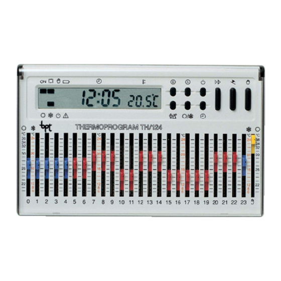
  • Seite 33 THERMOPROGRAM °C einstellbar. THERMOPROGRAM ist im allge- meinen für die Steuerung von Heizungen und TH124 Klimaanlagen verwendbar und kann anstelle eines vorhandenen Thermostaten mit Aus- /Einschaltfunktion installiert werden. Der programmierbare Raumthermostat THER- MOPROGRAM TH124 wurde so konzipiert, dass zu jeder Tageszeit ideale Temperaturbedingun- gen gesichert werden.
  • Seite 34 15 17 14 16 18 19 20 21 Abb. 1...
  • Seite 35 ANZEIGEN Digital-Thermometer. (Abb. 1) Batterieladezustand. Anzeige des Anlagenausschlus- Diese Schrift zeigt an, dass die ses. Batterien leer sind Anzeige für Anlage in MANUEL- LEM Betrieb. 11 6÷24°C Temperatur-Skala für Heizpro- gramm ( Anzeige für Anlage in AUTOMATI- SCHEM Betrieb. 12 20÷36°C Temperatur-Skala für Klimatisier- ungsprogramm ( Anzeige des Heizprogramms.
  • Seite 36 14 R Resettaste. Cursor für die Eingabe der Temperatur MANUELLEM Taste für die Wahl des Klimatisier- Betrieb. ungs- ( ) oder Heizprogramms Cursoren für die Eingabe der 0÷23 stündlichen Temperatur in AUTO- Taste für die Sichtanzeige der MATISCHEM Betrieb. Betriebszeit der Anlage. Cursorfarbe zeigt Tageszeiten der eingeschalteten...
  • Seite 37 INHALTSVERZEICHNIS 10 - Betriebszeit der Anlage 11 - Sichtbarmachung der Kapitel Seite programmierten Temperaturen 1 - Installationsort 12 - Ausschluss der Anlage 2 - Installation 13 - Zeitgeregelter Ausschluss der Anlage 3 - Versorgung 14 - Wechseln der Batterien 4 - Wärmedifferential 15 - Funktionsstörungen des Gerätes 5 - Einstellen der Uhr 16 - Technische Daten...
  • Seite 38: Installationsort

    1 - INSTALLATIONSORT 2 - INSTALLATION Installieren Sie das Gerät an einer Innenwand Die Taste P (Abb. 3) drücken und gleichzeitig (Abb. 2) und an einer Stelle, an der die Raum- dazu in Pfeilrichtung ziehen, um das Gerät zu temperatur korrekt gemessen werden kann; ver- öffnen.
  • Seite 39 Abb. 4 Abb. 5...
  • Seite 40 Abb. 6 Abb. 7...
  • Seite 41: Elektroanschlüsse

    ACHTUNG. Zur Gewährleistung eines einwandfreien Betriebs sollte das Gerät auf einer ebenen Fläche aufgestellt werden. Schrauben nicht zu fest anziehen! ELEKTROANSCHLÜSSE Die Anschlüsse richten sich nach dem Typ der von dem Thermostat gesteuerten Anlage; befolgen Sie den Schaltplan der Abb. 8 oder der Abb. 9. Anschließend den Klemmendeckel wieder befe- stigen.
  • Seite 42: Versorgung

    Belastungen U1 = Brenner, Umwälzpumpe, Elektroventil, etc. U2 = motorisiertes Ventil 3 - VERSORGUNG Drei alkalische Batterien LR6 Typ AA Mignon zu 1,5 V unter Berücksichtigung der Polaritätsmar- kierungen am Boden des Batterieraums (Abb. 10) einsetzen. ACHTUNG. Falsch eingesetzte Batterien kön- nen das Gerät beschädigen.
  • Seite 43 Abb. 10 Abb. 11...
  • Seite 44: Wärmedifferential

    °C °C °C °C °C °C °C °C Abb. 13 Abb. 12 Nun werden die Uhrzeit, die Raumtemperatur und der Batterieladezustand angezeigt. 4 - WÄRMEDIFFERENTIAL Das Wärmedifferential ist von ±0,1 °C bis ±0,9 °C °C °C °C °C einstellbar. THERMOPROGRAM wird mit einer Voreinstellung des Wärmedifferentials von ±0,2 Abb.
  • Seite 45: Einstellen Der Uhr

    °C °C °C °C °C °C °C °C Abb. 15 Abb. 17 Raumtemperatur angezeigt. ANMERK. Wenn die Neustartaste R gedrückt wird, stellt sich das Wärmedifferential auf ±0,2 °C ein. 5 - EINSTELLEN DER UHR °C °C °C °C 5.1 - Die Taste (Abb.
  • Seite 46 °C °C °C °C °C °C °C °C Abb. 18 Abb. 19 Displays während der ersten 5 s langsam und dann nach und nach schneller ab. 5.3 - Die Taste (Abb. 17) drücken. Die Stundenziffern blinken. 5.4 - Die Taste (Abb.
  • Seite 47: Heiz- Und Klimatisierungsprogramm

    °C °C °C °C °C °C °C °C Abb. 21 Abb. 22 6 - HEIZ- UND KLIMATISIERUNGS- 7 - AUTOMATISCHE PROGRAMM PROGRAMMIERUNG Durch Drücken der Taste (Abb. 20) wird Die Anzeige AUT zeigt an, dass die Anlage im das Klimatisierungs- oder Heizprogramm AUTOMATISCHEN Betrieb läuft.
  • Seite 48: Manueller Betrieb

    °C °C °C °C °C °C °C °C Abb. 23 Abb. 24 den Cursor eingestellt wurde, und die Position an °C °C °C °C (Abb. 23). Diese Programmierung kann jederzeit einfach durch Verstellen der Cursoren auf die gewünsch- te Stelle verändert werden. 8 - MANUELLER BETRIEB Abb.
  • Seite 49: Ferienprogramm

    °C °C °C °C °C °C °C °C Abb. 26 Abb. 27 neue Operation durchgeführt wird, welche den Nachdem die gewünschte Dauer eingestellt AUTOMATISCHEN Betrieb wiederherstellt. wurde, beginnt die Vorrichtung mit dem Count down, nach dessen Ablauf das Gerät vom 9 - FERIENPROGRAMM MANUELLEN zum AUTOMATISCHEN Betrieb übergeht und dem eingestellten Programm folgt.
  • Seite 50 °C °C °C °C °C °C °C °C Abb. 28 Abb. 29 gewünschte Stundenzahl von 1 bis 99 erreicht ist. Stundenzahl auch jene Augenblicks der Programmierung enthalten (das heißt der Rest der Stunde des Programmierens wird als 1 Stunde gezählt). °C °C °C...
  • Seite 51: Betriebszeit Der Anlage

    °C °C °C °C °C °C °C °C Abb. 31 Abb. 33 ANMERK. Um vor Ablauf der programmierten Zeit zum AUTOMATISCHEN Betrieb zurückzu- kehren, die Taste drücken (Abb. 33). 10 - BETRIEBSZEIT DER ANLAGE °C °C °C °C THERMOPROGRAM ist mit einem Betriebsstunden- zähler (bis 9.999) ausgestattet, mit dem die Betriebs- Abb.
  • Seite 52: Sichtbarmachung Der Programmierten Temperaturen

    °C °C °C °C °C °C °C °C Abb. 34 Abb. 36 11 - SICHTBARMACHUNG DER PROGRAMMIERTEN TEMPERATUREN 11.1 - Die Taste (Abb. 36) drücken. Am Display erscheint 5 s lang die für die ange- °C °C °C °C gebene Stunde eingestellte Temperatur. Wenn die Uhr beispielsweise 11.45 zeigt und der Abb.
  • Seite 53: Ausschluss Der Anlage

    °C °C °C °C °C °C °C °C Abb. 37 Abb. 38 der Temperatur hat die Bezeichnung C25. 12.2 - Durch erneutes Drücken der Taste wird THERMOPROGRAM wieder eingeschaltet. 12 - AUSSCHLUSS DER ANLAGE 13 - ZEITGEREGELTER Diese Funktion ist nützlich während winterlichen AUSSCHLUSS DER ANLAGE Reinigungen, Wartungsarbeiten, sommerlicher Abwesenheit, etc.;...
  • Seite 54 °C °C °C °C °C °C °C °C Abb. 39 Abb. 40 Anstelle der laufenden Uhrzeit erscheint am Display die Aufschrift h01. Die Anzeige der Raumtemperatur schaltet sich für 5 s aus und es wird eingeblendet. 13.3 - Die Taste (Abb.
  • Seite 55 °C °C °C °C °C °C °C °C Abb. 42 Abb. 43 13.5 - Die Taste zweimal drücken (Abb. 43). Anstelle der laufenden Uhrzeit erscheint am Display die Aufschrift d01. Die Anzeige der Raumtemperatur schaltet sich für 5 s aus und es wird eingeblendet.
  • Seite 56: Wechseln Der Batterien

    °C °C °C °C °C °C °C °C Abb. 45 Abb. 46 14 - WECHSELN DER BATTERIEN Die blinkende Anzeige am Display zeigt an, dass die Batterien innerhalb etwa 1 Monats gewechselt werden müssen (Abb. 46). °C °C °C °C Wenn auf dem Display die Anzeige das Symbol erscheinen, ist das Gerät nicht...
  • Seite 57 1,5 V unter Berücksichtigung der Polaritätsmar- kierungen am Boden des Batterieraums einset- zen (Abb. 49). Sollten die Display-Anzeigen, innerhalb von 30 Sekunden, nicht erscheinen, die Resettaste R drücken. ACHTUNG. Falsch eingesetzte Batterien kön- nen das Gerät beschädigen. Die für das Wechseln der Batterien verfügbare Zeit beträgt ungefähr 2 min.
  • Seite 58 Abb. 50 Abb. 49...
  • Seite 59: Funktionsstörungen Des Gerätes

    15 - FUNKTIONSSTÖRUNGEN DES GERÄTES Im Falle von Funktionsstörungen die Resettaste R drücken. Bei diesem Vorgang gehen die Einstellungen verloren, die den Angaben des Kapitels 4 ent- sprechend wiederherstellbar sind. °C °C °C °C °C °C Das Erscheinen einer Anzeige von E00÷E23 und E25 (Cursor des manuellen Betriebs) zeigt an, dass sich der entsprechende Cursor an der fal- schen Stelle befindet und folglich auf das...
  • Seite 60 • Versorgung: 3 alkalische Batterien LR6 Typ AA • Messintervall der Raumtemperatur: 15 s. zu 1,5V. • Wärmedifferential: von ±0,1 bis ±0,9 °C ein- • Autonomie: über 1 Jahr. stellbar. • Anzeige Batterie leer. • Ableseauflösung: 0,1 °C. • Verfügbarer Zeitraum für das Wechseln der •...
  • Seite 61: Allgemeine Garantiebedingungen

    ALLGEMEINE ENTSORGUNG GARANTIEBEDINGUNGEN Vergewissern Sie sich, dass das Verpackungs- material gemäß den Vorschriften des Bestim- Der Vertriebshändler vor Ort ist unter Beachtung mungslandes ordungsgemäß und umwelt- der geltenden Landesgesetze für die Produkt- gerecht entsorgt wird. garantie zuständig. Das nicht mehr benutzbare Gerät ist umwelt- gerecht zu entsorgen.
  • Seite 62: Instructions Pour L'installateur

    Nous vous félicitons et vous remercions d'avoir INSTRUCTIONS POUR acheté le thermostat TH124. L'INSTALLATEUR Afin d'obtenir les meilleures performances et d'exploiter au mieux les caractéristiques et les • Lire attentivement les instructions contenues fonctions de votre thermostat, lire attentivement dans la présente notice car elles fournissent des cette notice et la garder à...
  • Seite 63 THERMOPROGRAM THERMOPROGRAM peut commander, d'une manière générale, aussi bien les installations de TH124 chauffage que les installations de rafraîchisse- ment et il peut être installé pour remplacer un Le thermostat programmable THERMOPRO- thermostat préexistant du type allumé/éteint. GRAM TH124 a été conçu pour garantir des con- ditions de température idéales tout au long de la journée.
  • Seite 64 15 17 14 16 18 19 20 21 Fig. 1...
  • Seite 65 INDICATIONS Thermomètre digital. (fig. 1) Etat de charge de la pile. Indicateur d'exclusion de l'installa- L'affichage de ce message indi- tion. que que les piles sont épuisées Indicateur de fonctionnement en mode MANUEL. 11 6÷24°C Plage de température pour pro- Indicateur de fonctionnement en gramme de chauffage ( mode AUTOMATIQUE.
  • Seite 66 14 R Bouton-poussoir de remise à zéro Bouton-poussoir pour l'activation (reset). du PROGRAMME VACANCES. Bouton-poussoir pour la sélection Bouton-poussoir pour la sélection du programme de rafraîchisse- du fonctionnement MANUEL ou ment ( ) ou de chauffage ( AUTOMATIQUE de l'appareil. Bouton-poussoir pour l'affichage Curseur pour le réglage de la tem- du temps de fonctionnement de...
  • Seite 67 SOMMAIRE 9 - Programme vacances 10 - Temps de fonctionnement Chapitre Page de l'installation 1 - Emplacement 11 - Affichage des températures programmées 2 - Installation 12 - Exclusion de l'installation 3 - Alimentation 13 - Exclusion temporisée de l'installation 4 - Différentiel thermique 14 - Remplacement des piles 5 - Réglage de l'horloge...
  • Seite 68: Emplacement

    1 - EMPLACEMENT 2 - INSTALLATION Installer l'appareil sur un mur intérieur (fig. 2), Ouvrir l'appareil en appuyant sur le bouton- dans une position permettant de détecter cor- poussoir P (fig. 3) et, en même temps, en tirant rectement la température du local. Eviter de l'in- dans le sens des flèches.
  • Seite 69 Fig. 4 Fig. 5...
  • Seite 70 Fig. 6 Fig. 7...
  • Seite 71: Connexions Electriques

    ATTENTION. Pour que l'appareil fonctionne correcte- ment, il est recommandé de l'installer sur une surfa- ce plane, en évitant de trop serrer les vis. CONNEXIONS ELECTRIQUES Les connexions doivent s'effectuer en fonction du type d'appareil commandé par le thermostat. Suivre donc soit le schéma de la fig. 8 soit celui de la fig.
  • Seite 72: Alimentation

    Charges U1 = brûleur, pompe de circulation, soupape électrique, etc. U2 = soupape motorisée 3 - ALIMENTATION Insérer 3 piles alcalines LR6, du type AA de 1,5 V l'une, en respectant les pôles indiqués dans le fond du boîtier prévu pour les loger (fig. 10). ATTENTION.
  • Seite 73 Fig. 10 Fig. 11...
  • Seite 74: Différentiel Thermique

    °C °C °C °C °C °C °C °C Fig. 13 Fig. 12 chauffage . L'heure, la température ambiante et l'indication de l'état de la pile s'affichent sur l'écran. 4 - DIFFERENTIEL THERMIQUE Le différentiel thermique peut être sélectionné de °C °C °C °C...
  • Seite 75: Réglage De L'horloge

    °C °C °C °C °C °C °C °C Fig. 16 Fig. 15 L'écran affiche le message d 0.2°C qui reste Les chiffres des minutes clignotent. visualisé pendant environ 10 s. 5.2 - Appuyer sur le bouton-poussoir (fig. 16) 4.2 - Appuyer sur le bouton-poussoir (fig.
  • Seite 76: Programme De Chauffage Ou De Rafraîchissement

    °C °C °C °C °C °C °C °C Fig. 17 Fig. 18 5.4 - Appuyer sur le bouton-poussoir (fig. 18) jusqu'à ce que l'on atteigne l'heure exacte. 5.5 - Appuyer sur le bouton-poussoir pour terminer la procédure de réglage (fig. 19). Les deux points entre les chiffres de l'heure et °C °C...
  • Seite 77: Fonctionnement Automatique

    °C °C °C °C °C °C °C °C Fig. 21 Fig. 20 20), on sélectionne le programme de rafraîchisse- mode MANUEL, appuyer sur le bouton-poussoir ment ou de chauffage . L'indicateur corre- (fig. 21) pour passer en mode AUTOMATI- spondant s'allume. Dans le programme rafraîchis- QUE.
  • Seite 78: Fonctionnement Manuel

    °C °C °C °C °C °C °C °C Fig. 24 Fig. 22 24) (l'indication sur l'écran affiche le choix effectué). 8.2 - Déplacer le curseur (fig. 25) au niveau de la température désirée (en se référant à la plage 6÷24 °C pour le programme de chauffage et à...
  • Seite 79 °C °C °C °C °C °C °C °C Fig. 25 Fig. 26 ple pour maintenir plus longtemps une tempéra- 9.2 - Appuyer sur le bouton-poussoir (fig. 27). ture agréable lors de visites non prévues ou une L'écran affichera h01 à la place de l'heure courante. température hors gel durant les absences en 9.3 - Appuyer sur le bouton-poussoir (fig.
  • Seite 80 °C °C °C °C °C °C °C °C Fig. 28 Fig. 27 Programmation en jours 9.4 - Sélectionner le mode MANUEL et régler la température désirée (fig. 30). 9.5 - Appuyer deux fois sur le bouton-poussoir (fig. 31). L'écran affichera d01 à la place du jour courant. °C °C °C...
  • Seite 81: Temps De Fonctionnement De L'installation

    °C °C °C °C °C °C °C °C Fig. 31 Fig. 30 10 - TEMPS DE FONCTIONNEMENT DE L'INSTALLATION THERMOPROGRAM est équipé d'un compteur horaire (jusqu'à 9.999) qui permet de compter °C °C °C °C les heures de fonctionnement de l'installation. 10.1 - Appuyer sur le bouton-poussoir (fig.
  • Seite 82: Affichage Des Températures Programmées

    °C °C °C °C °C °C °C °C Fig. 33 Fig. 34 11 - AFFICHAGE DES TEMPERATURES PROGRAMMEES 11.1 - Appuyer sur le bouton-poussoir (fig. 36). L'écran affiche, pendant 5 s, la température °C °C °C °C réglée relative à l'heure indiquée. Par exemple, si l'horloge indique 11.45 et si le Fig.
  • Seite 83: Exclusion De L'installation

    °C °C °C °C °C °C °C °C Fig. 36 Fig. 37 12 - EXCLUSION DE L'INSTALLATION soir pour réactiver le THERMOPROGRAM dans le contrôle de l'installation. Cette position est utile lors des nettoyages en 13 - EXCLUSION TEMPORISEE DE hiver, de la maintenance, des absences en été, L'INSTALLATION etc.
  • Seite 84 °C °C °C °C °C °C °C °C Fig. 38 Fig. 39 avant la fin du temps programmé, appuyer sur le 13.2 - Appuyer sur le bouton-poussoir (fig. 39). bouton-poussoir (fig. 41). L'écran affichera h01 à la place de l'heure courante. L'indication de la température ambiante dispara- Programmation en jours ît pendant 5 s et on voit s'afficher...
  • Seite 85: Remplacement Des Piles D'alimentation

    °C °C °C °C °C °C °C °C Fig. 40 Fig. 41 Le calcul des jours comprend également celui que les piles doivent être remplacées avant envi- où l'on effectue la programmation (le restant du ron 1 mois (fig. 46). jour où...
  • Seite 86 °C °C °C °C °C °C °C °C Fig. 42 Fig. 44 de 1,5 V l'une, en respectant les pôles indiqués dans le fond du boîtier (fig. 49). Si les indications sur le display ne disparais- sent pas dans les 30 secondes, appuyer sur la touche de reset R.
  • Seite 87: Anomalies Dans Le Fonctionnement De L'appareil

    °C °C °C °C °C °C °C °C Fig. 45 Fig. 46 Pour la remise en marche de l'appareil, procé- der comme décrit à partir du chapitre 4. Refermer l'appareil en veillant à bien insérer les crochets dans leurs logements respectifs (fig. 50). Après quelques secondes, les indications réap- °C °C...
  • Seite 88: Caractéristiques Techniques

    L'affichage d'une indication comprise entre E00÷E23 et E25 (curseur du mode manuel) signale que le curseur correspondant est mal positionné et doit donc être aligné sur le seg- ment de la température désirée (fig. 51). 16 - CARACTERISTIQUES TECHNIQUES Appareil à usage civil. •...
  • Seite 89 Fig. 50 Fig. 49...
  • Seite 90 • Type d'action: 1B-U. • Plage de réglage en mode chauffage: de 6 °C à 24 °C. • Plage de réglage en mode rafraîchissement: de 20 °C à 36 °C. • Trois modes de fonctionnement: MANUEL, AUTOMATIQUE, EXCLUSION INSTALLATION. • Programmes sélectionnables: CHAUFFAGE, °C °C °C...
  • Seite 91 • Logiciel de classe A. • Degré de pollution: 2. • Tension impulsive: 4 kV. • Température maximale de la tête de comman- de: 40 °C. • Température de fonctionnement: de 0 °C à +40 °C. • Indice de protection: IP30. •...
  • Seite 93: Conditions Générales De Garantie

    CONDITIONS GENERALES ELIMINATION DE GARANTIE S'assurer que le matériel d’emballage n’est pas abandonné dans la nature et qu’il est éliminé La garantie sur le produit sera fournie par le dis- conformément aux normes en vigueur dans le tributeur local conformément aux lois en vigueur pays d'utilisation du produit.
  • Seite 96 BPT S.p.A. http: www.bpt.it/e-mail: info@bpt.it Via Roma, 41 30020 Cinto Caomaggiore-VE-Italy...

Inhaltsverzeichnis