Grundig ms 4101 Serviceanleitung
Inhaltsverzeichnis
HiFi
Zusätzlich erforderliche Unterlagen für den Komplettservice
Additionally required Service Documents for the Complete Service
Service
Manual
Sicherheit
Safety
Materialnr./Part No.
720108000000
Materialnummer/Part Number 720107717000
Änderungen vorbehalten/Subject to alteration • Printed in Germany • WÜ
E-BS-SA16 1001 • 8002/8012, 8005/8015, 8006/8016
http://www.grundig.com
Service Manual
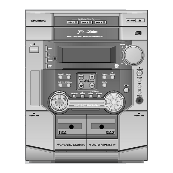
MS 4101
GLM0150
Grundig Service
Technik:
TV
TV
SAT
VCR/LiveCam
HiFi/Audio
Car Audio
Telekommunikation
Fax:
Planatron
(8.00-22.00 Uhr)
Ersatzteil-Verkauf:
Telefon:
Fax:
Kundendienst/Werkstätten:
Telefon:
Fax:
gebührenpflichtig
Hotline Deutschland...
...Mo.-Fr. 8.00-18.00 Uhr
0180/52318-41
0180/52318-49
0180/52318-48
0180/52318-42
0180/52318-43
0180/52318-44
0180/52318-45
0180/52318-51
0180/52318-99
Mo.-Fr. 8.00-19.00 Uhr
0180/52318-40
0180/52318-50
Mo.-Fr. 8.00-18.00 Uhr
0180/52318-52
0180/52318-46
Inhaltsverzeichnis

Verwandte Anleitungen für Grundig ms 4101


Inhaltszusammenfassung für Grundig ms 4101
- Seite 1 Service Manual HiFi MS 4101 GLM0150 Grundig Service Hotline Deutschland… …Mo.-Fr. 8.00-18.00 Uhr Technik: 0180/52318-41 0180/52318-49 Zusätzlich erforderliche Unterlagen für den Komplettservice 0180/52318-48 Additionally required Service Documents for the Complete Service VCR/LiveCam 0180/52318-42 HiFi/Audio 0180/52318-43 Service Car Audio 0180/52318-44 Manual...
-
Seite 2: Inhaltsverzeichnis
Digital voltmeter Testcassette 3150Hz/10kHz (z.B. 448) Test cassette 3150Hz/10kHz (e.g. 448) Beachten Sie bitte das GRUNDIG Messtechnik-Programm, das Sie Please note the GRUNDIG Catalog "Test and Measuring Equipment" unter folgender Adresse erhalten: obtainable from: GRUNDIG AG Geschäftsbereich Instruments Test- und Mess-Systeme Würzburger Str. -
Seite 3: Technische Daten
MS 4101 Allgemeiner Teil / General Section Technische Daten Technical Data Verstärkerteil Amplifier unit Ausgangsleistung: Output power: Sinusleistung ..............2 x 85W Sinusoidal power ............. 2 x 85W Musikleistung ..............2 x 170W Music signal power ............2 x 170W Maximalleistung .............. -
Seite 4: Disassembly Instructions
Allgemeiner Teil / General Section MS 4101 Ausbauhinweise Disassembly Instructions Bevor Sie Leitungen lösen, muss die Leitungsverlegung beachtet Before disconnecting any leads observe the way they are routed. werden. Nach erfolgter Reparatur ist es notwendig, die Leitungs- On completion of the repairs the leads must be laid out as führung in den werkseitigen Zustand zu versetzen. - Seite 5 MS 4101 Allgemeiner Teil / General Section 3. CD-Laufwerk 3. CD Mechanism - Gehäuseoberteil (Punkt 1) und Gehäuseseitenteile (Punkt 2) ab- - Remove the cabinet top (para 1) and the cabinet sides (para 2). nehmen. - Open the CD tray (if the tray drive is defective see para 3.1).
- Seite 6 Allgemeiner Teil / General Section MS 4101 3.3 Schubladenantrieb 3.3 Tray Drive - Schublade ausbauen (Punkt 3.2). - Remove the tray (para 3.2). - Die Zahnräder können nun abgeschraubt werden. - The toothed wheels can now be unscrewed. - Einbau siehe Punkt 3.2 Montage.
- Seite 7 MS 4101 Allgemeiner Teil / General Section 3.7 Drehteller-Antrieb 3.7 Turntable Drive - Schublade ausbauen (Punkt 3.2) - Remove the tray (para 3.2) - Schraube R (Fig. 14) herausdrehen. - Undo screw R (Fig. 14). - Der Antrieb ist nun zugänglich.
- Seite 8 Allgemeiner Teil / General Section MS 4101 9. Hauptplatte 9. Main PCB - Frontblende lösen (Punkt 8). - Loosen the front (para 8). - Undo screw B (Fig. 16). - Schraube B (Fig. 16) herausdrehen. - Schraube C (Fig. 1) herausdrehen.
- Seite 9 MS 4101 Allgemeiner Teil / General Section Bedienhinweise Dieses Kapitel enthält Auszüge aus der Bedienungsanleitung. Weitergehende Informationen entnehmen Sie bitte der gerätespezifischen Bedienungsanleitung, deren Materialnummer Sie in der entsprechenden Ersatzteilliste finden. GRUNDIG Service 1 - 9...
- Seite 10 Allgemeiner Teil / General Section MS 4101 1 - 10 GRUNDIG Service...
- Seite 11 MS 4101 Allgemeiner Teil / General Section GRUNDIG Service 1 - 11...
- Seite 12 Allgemeiner Teil / General Section MS 4101 1 - 12 GRUNDIG Service...
- Seite 13 MS 4101 Allgemeiner Teil / General Section GRUNDIG Service 1 - 13...
-
Seite 14: Operating Hints
Allgemeiner Teil / General Section MS 4101 Operating Hints This chapter contains excerpts from the operating instructions. For further particulars please refer to the appropriate user instructions the part number of which is indicated in the relevant spare parts list. - Seite 15 MS 4101 Allgemeiner Teil / General Section GRUNDIG Service 1 - 15...
- Seite 16 Allgemeiner Teil / General Section MS 4101 1 - 16 GRUNDIG Service...
- Seite 17 MS 4101 Allgemeiner Teil / General Section GRUNDIG Service 1 - 17...
- Seite 18 Allgemeiner Teil / General Section MS 4101 1 - 18 GRUNDIG Service...
- Seite 19 MS 4101 Abgleichvorschriften / Adjustment Procedures Abgleichvorschriften Tuner Messgeräte: Wobbel- / Mess-Sender, Oszilloskop, Digital-Voltmeter Hinweis: Das Frontend ist ein komplett abgeglichener Baustein. Nur das ZF-Filter muss dem ZF-Verstärker angeglichen werden (Punkt 7). Abgleich Vorbereitung Abgleichvorgang ± 1. MW-Oszillator MW, 522kHz;...
- Seite 20 Abgleichvorschriften / Adjustment Procedures MS 4101 Cassette Messgeräte: Frequenzzähler, Oszilloskop, Test-Cassette 3150Hz/10kHz (z.B. 448) Abgleich Vorbereitung Abgleichvorgang ± 1. Lösch-Oszillator Frequenzzähler an Messpunkt (JCW1-(5)). Mit JL1 auf 105kHz 0,5kHz abgleichen. Leer-Cassette einlegen und Aufnahme starten. 2. Vormagnetisierung Leer-Cassette in Deck 2 einlegen und Aufnahme starten.
-
Seite 21: Adjustment Procedures
MS 4101 Abgleichvorschriften / Adjustment Procedures Adjustment Procedures Tuner Test equipment: Sweep / Signal Generator, Oscilloscope, Digital Voltmeter Note: The frontend is a completely preadjusted module. Only the IF filter must be adjusted to the IF amplifier (para 7). Adjustment... -
Seite 22: Cassette
Abgleichvorschriften / Adjustment Procedures MS 4101 Cassette Test equipment: Frequency Counter, Oscilloscope, Test Cassette 3150Hz/10kHz (z.B. 448) Adjustment Preparation Adjustment Procedure ± 1.Bias Oscillator Frequency Counter to Testpoint (JCW1-(5)). Adjust JL1 for 105kHz 0.5kHz. Insert empty Cassette and start recording. -
Seite 23: Circuit Diagrams And Layout Of The Pcbs
MS 4101 Schaltpläne und Platinenabbildungen / Circuit Diagrams and Layout of the PCBs MS 4101 Schaltpläne und Platinenabbildungen / Circuit Diagrams and Layout of the PCBs Schaltpläne und Platinenabbildungen / Circuit Diagrams and Layout of the PCBs Haupt-Platte (Teil 1) / Main Board (Part 1) to CW106 S./p. - Seite 24 Schaltpläne und Platinenabbildungen / Circuit Diagrams and Layout of the PCBs MS 4101 Schaltpläne und Platinenabbildungen / Circuit Diagrams and Layout of the PCBs MS 4101 to ACW2-1 Haupt-Platte (Teil 2) / Main Board (Part 2) S./p. 3-7 to LCW10 S./p.
- Seite 25 MS 4101 Schaltpläne und Platinenabbildungen / Circuit Diagrams and Layout of the PCBs MS 4101 Schaltpläne und Platinenabbildungen / Circuit Diagrams and Layout of the PCBs Sicht auf Bestückungsseite / View on Component Side GRUNDIG Service 3 - 5 GRUNDIG Service...
- Seite 26 Schaltpläne und Platinenabbildungen / Circuit Diagrams and Layout of the PCBs MS 4101 Schaltpläne und Platinenabbildungen / Circuit Diagrams and Layout of the PCBs MS 4101 NF-Verstärker / AF Amplifier Spannungen / Voltages AIC1 -54V -10V +54V to HCW1-1 -24V -55V S./p.
- Seite 27 MS 4101 Schaltpläne und Platinenabbildungen / Circuit Diagrams and Layout of the PCBs MS 4101 Schaltpläne und Platinenabbildungen / Circuit Diagrams and Layout of the PCBs Sicht auf Bestückungsseite / View on Component Side GRUNDIG Service 3 - 9 GRUNDIG Service...
- Seite 28 Schaltpläne und Platinenabbildungen / Circuit Diagrams and Layout of the PCBs MS 4101 Schaltpläne und Platinenabbildungen / Circuit Diagrams and Layout of the PCBs MS 4101 to CW105 Front-Platte / Front Board S./p. 3-16 to FCW1 S./p. 3-1 Keys1 Keys2...
- Seite 29 MS 4101 Schaltpläne und Platinenabbildungen / Circuit Diagrams and Layout of the PCBs MS 4101 Schaltpläne und Platinenabbildungen / Circuit Diagrams and Layout of the PCBs Sicht auf Bestückungsseite / View on Component Side GRUNDIG Service 3 - 13 GRUNDIG Service...
- Seite 30 Schaltpläne und Platinenabbildungen / Circuit Diagrams and Layout of the PCBs MS 4101 Schaltpläne und Platinenabbildungen / Circuit Diagrams and Layout of the PCBs MS 4101 CD-Platte / CD Board to CCW1 S./p. 3-1 to OCW1 S./p. 3-23 to FCW2...
- Seite 31 MS 4101 Schaltpläne und Platinenabbildungen / Circuit Diagrams and Layout of the PCBs MS 4101 Schaltpläne und Platinenabbildungen / Circuit Diagrams and Layout of the PCBs Sicht auf Bestückungsseite / View on Component Side Sicht auf Lötseite / View on Solder Side...
- Seite 32 Schaltpläne und Platinenabbildungen / Circuit Diagrams and Layout of the PCBs MS 4101 Schaltpläne und Platinenabbildungen / Circuit Diagrams and Layout of the PCBs MS 4101 Tuner Spannungen / Voltages IC01 Spannungen / Voltages IC02 Spannungen / Voltages IC02 to TCW1 S./p.
- Seite 33 MS 4101 Schaltpläne und Platinenabbildungen / Circuit Diagrams and Layout of the PCBs MS 4101 Schaltpläne und Platinenabbildungen / Circuit Diagrams and Layout of the PCBs Sicht auf Bestückungsseite / View on Component Side Sicht auf Lötseite / View on Solder Side...
- Seite 34 Schaltpläne und Platinenabbildungen / Circuit Diagrams and Layout of the PCBs MS 4101 Schaltpläne und Platinenabbildungen / Circuit Diagrams and Layout of the PCBs MS 4101 Standby-Netzteil / Standby Power Supply Standby-Netzteil Standby Power Supply Netz / Mains 230V~ 50/60Hz to RCW3 S./p.
-
Seite 35: Main Board
MS 4101 Schaltpläne und Platinenabbildungen / Circuit Diagrams and Layout of the PCBs MS 4101 Schaltpläne und Platinenabbildungen / Circuit Diagrams and Layout of the PCBs Verdrahtungsplan / Wiring Diagram Tuner CON01 Jog-Platte FCW1 CD-Tasten-Platte Jog Board FCW3-1 FCW4-1 CD Key Board... -
Seite 36: Ic Block Diagrams
Schaltpläne und Platinenabbildungen / Circuit Diagrams and Layout of the PCBs MS 4101 Schaltpläne und Platinenabbildungen / Circuit Diagrams and Layout of the PCBs MS 4101 IC-Innenbeschaltungen / IC Block Diagrams IC301 KA 9258 D IC02 LC 72131 M REVERENCE... - Seite 37 MS 4101 Explosionszeichnungen und Ersatzteilliste / Exploded Views and Spare Parts List MS 4101 Explosionszeichnungen und Ersatzteilliste / Exploded Views and Spare Parts List Explosionszeichnungen und Ersatzteilliste / Exploded Views and Spare Parts List GRUNDIG Service 4 - 1 GRUNDIG Service...
- Seite 38 Explosionszeichnungen und Ersatzteilliste / Exploded Views and Spare Parts List MS 4101 Explosionszeichnungen und Ersatzteilliste / Exploded Views and Spare Parts List MS 4101 CD-Laufwerk / CD Drive Cassetten-Laufwerk / Tape Drive 4 - 3 GRUNDIG Service 4 - 4...
-
Seite 40: Ersatzteilliste Spare Parts List
PUFFER GRUEN CUSHION GREEN © POS. NO. FIG. PART NUMBER QTY. 759550159000 LAUFWERK CASS ADR246ANW DRIVE MECHANISM ADR246AMW 755098105000 MS 4101 CHROM MS 4101 CHROM 0001.000 759550159100 KOMBI KOPF ADR2400-RP COMBINATION HEAD ADR2400- KEIN E-TEIL NO SPARE PART 0002.000 759550159200... - Seite 41 POS. NR. MATERIAL-NR. BEZEICHNUNG POS. NR. MATERIAL-NR. BEZEICHNUNG POS. NO. PART NUMBER DESCRIPTION POS. NO. PART NUMBER DESCRIPTION POS. NR. MATERIAL-NR. BEZEICHNUNG POS. NR. MATERIAL-NR. BEZEICHNUNG POS. NO. PART NUMBER DESCRIPTION POS. NO. PART NUMBER DESCRIPTION FQ 0002R 759510451400 TRANS.KSC 945 Y O JACK 759550445100 BUCHSE OPTICAL...