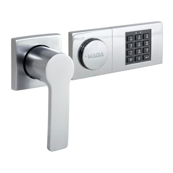
Kaba Combi B 30 Montageanleitung
Mit metall-eingabeeinheit
Vorschau ausblenden
Andere Handbücher für Combi B 30:
- Bedienungsanleitung (24 Seiten) ,
- Bedienungsanleitung (37 Seiten)
Inhaltsverzeichnis
Verfügbare Sprachen
Verfügbare Sprachen
Kapitel
Inhaltsverzeichnis

Verwandte Anleitungen für Kaba Combi B 30


Inhaltszusammenfassung für Kaba Combi B 30
- Seite 1 Combi B 30 mit Metall-Eingabeeinheit Montageanleitung Version DE + EN...
-
Seite 2: Inhaltsverzeichnis
Montageanleitung 82132/3xxx CB 30 Inhaltsverzeichnis Hinweise ................................4 Technische Daten .............................. 4 Spannungsversorgung ............................... 4 Schloss ..................................4 Schnittstellen Schloss ..............................5 Schnittstellen Eingabeeinheit ............................ 6 Lieferumfang ..............................7 Montagevorbereitung ............................8 Bohrungen und Schrankdurchbrüche Schloss ......................8 Bohrungen und Schrankdurchbrüche Eingabeeinheit ..................10 Antriebswelle ................................ - Seite 3 Montageanleitung 82132/3xxx CB 30 Abbildungsverzeichnis Abbildung 1: Anschlussbuchsen Schloss ............................5 Abbildung 2: Anschluss Eingabeeinheit ............................6 Abbildung 3: Explosionsansicht Schlosssystem ..........................7 Abbildung 4: Montagelochbild Schloss; Maße Schlossgehäuse ..................... 8 Abbildung 5: Schlüsselführung 86101 ............................9 Abbildung 6: Schlüsselträgerführung .............................. 9 Abbildung 7: Bohrlöcher Bedieneinheit und möglicher Bereich für Kabeldurchbruch ..............
-
Seite 4: Hinweise
12V-Netzteil (Art. Nr. 3002501230) über ein 9V-Netzteil (Art. Nr. 3002501220) direkt an der „power“ Anschlussbuchse des Schlosses Achtung: Es wird dringend empfohlen die original Kaba Mauer Netzteile (Artikelnummern siehe oben) zu verwenden, da andernfalls die korrekte Funktion des Schlosssystems nicht sichergestellt werden kann. -
Seite 5: Schnittstellen Schloss
Funktion möglich; Übersteuerung Doppelcode 12V +/-10 % Siehe Fernsperre Standard: deaktiviert)) power Permanent- Anschluss für optionales Combi B 30 Gemäß Vorbelegung spannungsver- Kaba Mauer Netzteil (Art. Nr. sorgung 3002501220) Anschluss für optionale Alarmbox Gemäß Vorbelegung (Art. Nr. 3001001550) Tabelle 1: Übersicht Anschlussbuchsen... -
Seite 6: Schnittstellen Eingabeeinheit
Kabel mit Kommunikationslinie Verbindungskabel und Stecker zum Schloss 6-polige Buchse Stecker zum Schloss I/O Mini- Datenschnittstelle Verbindet die Eingabeeinheit mittels des Kaba Gemäß interner Vorbelegung. USB- zum PC Mauer CB30-PC-Kabels mit dem PC, um das Achtung: Sonderschnitt- Buchse Audit auszulesen... -
Seite 7: Lieferumfang
Montageanleitung 82132/3xxx CB 30 Lieferumfang Abbildung 3: Explosionsansicht Schlosssystem Im Lieferumfang enthalten: (1) Schloss (2) Antriebswelle (3) O-Ring (4) Revisionsschlüssel (5) Inbusschlüssel (6) Schraube zur Arretierung des Oberteils der Eingabeeinheit (F-H-2,9 x 6,5 mm) ... -
Seite 8: Montagevorbereitung
Montageanleitung 82132/3xxx CB 30 Montagevorbereitung Bohrungen und Schrankdurchbrüche Schloss Zur Montage des Schlosses (Nr. 1 in Abbildung 3) sind 4 Bohrungen mit M6 Gewinde erforderlich. Diese sind gemäß des in Abbildung 4 gezeigten Lochbildes zu erstellen. Gegebenenfalls ist das gezeigte Lochbild für die gewünschte Einbaulage nach Tabelle 4 zu drehen. -
Seite 9: Abbildung 5: Schlüsselführung 86101
Montageanleitung 82132/3xxx CB 30 Es wird empfohlen, für die Absicherung des erforderlichen Schlüsseldurchbruchs im Wertbehältnis die Kaba Mauer Schlüsselführung (siehe Abbildung 5) oder die Kaba Mauer Schlüsselträgerführung (siehe Abbildung 6) einzusetzen. In diesen Fällen ist unter der Berücksichtigung der DIN 2768-mH das Schlüsselloch in der Tür des Wertbehältnisses in den entsprechenden Abmessungen zu fertigen. -
Seite 10: Bohrungen Und Schrankdurchbrüche Eingabeeinheit
Montageanleitung 82132/3xxx CB 30 Bohrungen und Schrankdurchbrüche Eingabeeinheit Zur Montage der Eingabeeinheit sind zunächst 3 Bohrungen mit M4 Gewinde gemäß der Abbildung 7 erforderlich. Es sind zwei Verschraubungsmöglichkeiten gegeben. Diese sind in der Abbildung 7 mit I bzw. II dargestellt. Je nach Einbaulage muss die Abbildung 7 gegebenenfalls entsprechend der Tabelle 5 gedreht werden. -
Seite 11: Antriebswelle
Montageanleitung 82132/3xxx CB 30 Antriebswelle Die mitgelieferte Antriebswelle (2) ist je nach Türstärke und Einbauposition auf die erforderliche Funktionslänge anzupassen, um die einwandfreie Funktion des Schlosssystems sicherzustellen. Das benötigte Längenmaß W ergibt sich aus dem Abstandsmaß L zwischen Montageebene Schloss zu Montageebene Eingabeeinheit + 20 mm Eintauchtiefe der Welle in die Eingabeeinheit + 26,5 mm Eintauchtiefe in das Schloss (Toleranz +0/-2 mm, siehe Abbildung 8). -
Seite 12: Montage Schlosssystem
Montageanleitung 82132/3xxx CB 30 Montage Schlosssystem Nach der Montagevorbereitung kann die eigentliche Montage des Schlosses (1) und der Eingabeeinheit (8 + 11) erfolgen. Montage Schloss Das Schloss (1) ist nach folgenden Vorgaben im Wertbehältnis zu befestigen: Die Montage des Schlosses (1) muss im geschlossenen Zustand (Riegel ausgeschlossen) erfolgen. -
Seite 13: Montage Eingabeeinheit
Montageanleitung 82132/3xxx CB 30 Montage Eingabeeinheit 5.3.1 Eingabeeinheit demontieren Die gelieferte Eingabeeinheit (8 + 11) ist ab Werk vormontiert. Zur Installation am Wertbehältnis ist die Eingabeeinheit zunächst wie folgt zu demontieren: Abbildung 11: Inbusschlüssel einführen Inbusschlüssel (5) wie in der Abbildung dargestellt in das kleine Loch in der Eingabeeinheit (8 + 11) bis zum Anschlag einführen. -
Seite 14: Tastaturbaugruppe Anpassen
Montageanleitung 82132/3xxx CB 30 5.3.2 Tastaturbaugruppe anpassen Die Tastaturbaugruppe im Oberteil der Eingabeeinheit (8) ist standardmäßig für die Einbaulage Drehgriff (7) links, Tastatur rechts, vormontiert. Soll diese Einbaulage beibehalten werden, ist dieses Kapitel zu überspringen. Wird die Eingabeeinheit jedoch in einer der drei anderen Einbaulagen montiert, muss die herausnehmbare Tastaturbaugruppe gedreht werden. Dazu ist zunächst die Tastaturbaugruppe aus dem Oberteil der Bedieneinheit (8) zu lösen. -
Seite 15: Abbildung 18: Tastaturbaugruppe Montieren
Montageanleitung 82132/3xxx CB 30 Einbaurichtung der Eingabeeinheit Drehung der Tastatur Ergebnis Drehgriff links, Tastatur rechts nicht erforderlich 90° gegen den Drehgriff oben, Tastatur unten Uhrzeigersinn Drehgriff unten, Tastatur oben 90° im Uhrzeigersinn Drehgriff rechts, Tastatur links 180° Tabelle 6: Einbauposition Eingabeeinheit, Hinweise für Abbildungen 15 bis 18 Abbildung 18: Tastaturbaugruppe montieren Stand 16.02.2016 Seite 15 von 40... -
Seite 16: Verbindungskabel Montieren
Montageanleitung 82132/3xxx CB 30 5.3.3 Verbindungskabel montieren Es muss sichergestellt sein, dass das Verbindungskabel (12) beim Einbau nicht beschädigt wird, da sonst Kurzschlussgefahr und damit eine Beschädigung des Schlosssystems besteht. Das Kabeldurchführungsloch und andere Führungsbereiche des Kabels (12) dürfen keine scharfen Kanten aufweisen. Im Bereich von Übergängen und beweglichen Teilen ist das Kabel (12) durch Schutzschläuche oder Kunststoffröhrchen zu schützen. -
Seite 17: Basisteil Befestigen
5.3.4 Basisteil befestigen Das Combi B 30 Basisteil (11) ist nun mit den drei beiliegenden Schrauben (9) wie in Abbildung 7 dargestellt auf der Behältnistür anzuschrauben (Bohrlochspezifikationen siehe Kapitel 4.2). Dabei ist auf eine saubere Kabelführung zu achten: Je nach Position des Kabeldurchführungsloches muss das Verbindungskabel (12) eventuell unter dem Basisteil (11) zum Kabeldurchführungsloch geführt werden. -
Seite 18: Eingabeeinheit Oberteil Montieren
Aufstecken darauf achten, dass geschlossenen Zustand des Schlosses (1) der „KABA“ Schriftzug bzw. die Öffnungsanzeige (15; kleine Mulde) waagerecht steht. Sollte der Drehgriff (7) nicht einrasten, üben Sie keine Gewalt aus, sondern kontrollieren die Wellenlänge, den korrekten Sitz der Schrauben (6 + 9) und des O-Rings sowie den korrekten Sitz des Oberteils (8) der Eingabeeinheit. -
Seite 19: Teilinbetriebnahme / Inbetriebnahme
Montageanleitung 82132/3xxx CB 30 Teilinbetriebnahme / Inbetriebnahme Wenn das Schlosssystem montiert wurde, kann eine Teilinbetriebnahme (nur mittels PC Software) oder eine komplette Inbetriebnahme (mittels PC Software oder über Eingabeeinheit) erfolgen. Bei der Teilinbetriebnahme wird zwar das Schlosssystem konfiguriert (z. B. Einstellung von Stillem Alarm, Doppelcode, Codevorbelegung), diese Einstellungen werden allerdings erst aktiv, wenn das Schloss vollständig in Betrieb genommen wird, indem der Mastercode aktiviert wird. -
Seite 20: A Notizen
Montageanleitung 82132/3xxx CB 30 Notizen Kaba Mauer GmbH Frankenstrasse 8-12 D-42579 Heiligenhaus Stand 16.02.2016 Seite 20 von 40...