Herunterladen Diese Seite drucken

Werbung

Verfügbare Sprachen
  • DE

Verfügbare Sprachen

  • DEUTSCH, seite 33
All manuals and user guides at all-guides.com
ISTRUZIONI PER L'USO
INSTRUCTIONS FOR USE
BEDIENUNGSANLEITUNG
NOTICE D'UTILISATION
INSTRUCCIONES PARA EL USO
GEBRUIKSAANWIJZING
I
GB
D
F
E
NL

Werbung

loading

Inhaltszusammenfassung für Elite Super Crono

  • Seite 1 All manuals and user guides at all-guides.com ISTRUZIONI PER L'USO INSTRUCTIONS FOR USE BEDIENUNGSANLEITUNG NOTICE D'UTILISATION INSTRUCCIONES PARA EL USO GEBRUIKSAANWIJZING...
  • Seite 2 Le caratteristiche tecniche dell'ELASTOGEL sono: elevata elasticità,resistenza alla lacerazione, all'abrasione e resi- stenza agli oli e ai solventi. ELITE ist stolz, ein weiteres Produkt präsentieren zu können, das in Zusammenarbeit mit dem Chemiekonzern BAYER *DECIBEL entstanden ist: ELASTOGEL. Bei ELASTOGEL handelt es...
  • Seite 3 (gemeten in Db*). • VERBETERT DE GRIP VAN DE BAND OP DE WEERSTAND ROLLER. ELITE, en collaboration avec BAYER, à étudié l'ELASTOGEL il • VERMINDERT BAND SLIJTAGE TOT 20%. s'agit d'un technopolymer appliqué au rouleau d'entraine- • VERMINDERT VIBRATIES EN VERHOOGT HET GEVOEL ment ,qui offre les aventages suivants: TIJDENS HET TRAPPEN MET DE PEDALEN.
  • Seite 4 All manuals and user guides at all-guides.com • IMPORTANTE • INTRODUZIONE • ASSEMBLAGGIO CAVALLETTO • MONTAGGIO BATTERIE DEL TRASMETTITORE • MONTAGGIO UNITA’ • INSTALLAZIONE DELLA BICICLETTA • INSTALLAZIONE DEL COMPUTER • UTILIZZO COMPUTER • IMPOSTAZIONI • UTILIZZO • AVVIO • SCHERMATE •...
  • Seite 5 All manuals and user guides at all-guides.com • IMPORTANT • INTRODUCTION • ASSEMBLAGE DU SUPPORT • ASSEMBLAGE BATTERIES DE L’EMETTEUR • ASSEMBLAGE UNITE • INSTALLATION DU VELO • INSTALLATION DE L’ORDINATEUR • UTILISATION DE L’ORDINATEUR • MISE EN MARCHE • PARAMETRES •...
  • Seite 6 Molte grazie per aver acquistato Super Crono Wireless. N°1 dado M6 (Rif.M) N°1 sacchetto accessori unità: Il Super Crono Wireless è un rullo di allenamento N°1 chiave esagonale completamente senza fili. Tutte le informazioni N°2 viti M6 x 55 mm (Rif.N) sono trasmesse via radio dall'unità...
  • Seite 7 All manuals and user guides at all-guides.com ASSEMBLAGGIO CAVALLETTO • Aprire il cavalletto e posizionarlo su una superficie. • Montare la base inferiore supporto unità (H) incernierata con la base superiore sup- porto unità (G) sul tubo metallico del caval- letto (fig.1).
  • Seite 8 All manuals and user guides at all-guides.com • Sulla base (G) ci sono tre coppie di fori; utilizza- MONTAGGIO BATTERIE re i diversi fori in base al diametro della ruota TRASMETTITORE della bicicletta : Estrarre l’unità di resistenza dal proprio per ruote da 29”, coppia di fori posteriori (fig.6);...
  • Seite 9 All manuals and user guides at all-guides.com • Fissare completamente le viti (N) (fig.9). re nella boccola sinistra (C) (fig.12). Per un bloc- caggio più sicuro della bicicletta sul cavalletto, assicurarsi che la leva dello sgancio rapido sia rivolta in senso orizzontale (fig.13). INSTALLAZIONE DELLA BICICLETTA •...
  • Seite 10 All manuals and user guides at all-guides.com • Se la leva (F) comincia a comprimere lo sgancio rapido nella posizione di lavoro anticipata (fig.16), avvitare il perno bussola sinistro (C) (fig.17) in modo tale che la leva cominci a lavorare all’inter- no dell’area di lavoro predefinita (quella delimita- ta da 30°...
  • Seite 11 All manuals and user guides at all-guides.com • Assicurarsi che la leva dello sgancio rapido sia all’interno degli scarichi del perno bussola sini- stra (C) (fig.24). • Qualora la ruota risultasse troppo spostata rispetto al centro del rullino (fig.25), spostare l’unità...
  • Seite 12 All manuals and user guides at all-guides.com • Qualora la regolazione precedente non fosse sufficiente, spostare l’intera base (G,H) allentando la vite di fissaggio della base e bloccarla nella posizione più corretta (fig.28 , 29 e 30). • Verificare la stabilità della bicicletta tirando e spingendo il tubo orizzontale del telaio ed agendo sulla sella.
  • Seite 13 IMPOSTAZIONI • Aprire il vano batterie ricavato sotto il display ed inserire le due batterie tipo AA che si trovano Per utilizzare correttamente il Super Crono nella scatoletta del computer. Rispettare il senso Wireless è inizialmente necessario impostare i della polarità indicato sulla sede delle batterie.
  • Seite 14 Ogni schermata è suddivisa in sei unità di resistenza. Per impostare correttamente aree con informazioni che variano a seconda della il computer per il Super Crono Wireless, impo- schermata in cui ci si trova. Durante la corsa si stare il numero "3". Questo numero dovrebbe può...
  • Seite 15 Velocità massima. Massima velocità raggiunta durante la corsa. ELV.G Guadagno in elevazione. Indica il dislivello ottenuto durante la corsa. Distanza totale percorsa. Distanza totale che è stata percorsa con il Super Crono Wireless. TOTAL TIME Tempo totale. Tempo totale che è stato utilizzato il Super Crono Wireless.
  • Seite 16 Tale abbinamento rimarrà per sempre anche in occasione della sostituzione delle batterie. BATTERIE SINCRONIZZAZIONE Il computer del Super Crono Wireless utilizza due batterie di tipo AA. L’autonomia del sistema dipen- La procedura di sincronizzazione permette di de dalla qualità di batteria che si utilizza.
  • Seite 17 Attenzione a non sudare sopra il display, perché potrebbe danneggiare il circuito elettronico. • Non conservate il Super Crono Wireless in luo- • Per il trasporto o per ridurre gli ingombri quan- ghi bagnati o umidi. Questo potrebbe danneggiare do non si utilizza il rullo si consiglia di chiudere il i componenti elettronici.
  • Seite 18 • Poiché i piedini sono costruiti in materiale mor- bido antiscivolo, potrebbe verificarsi che durante l’uso lascino tracce di gomma sul pavimento. • Durante l’uso del Super Crono Wireless con rullino Elastogel, una leggera usura dello stesso rientra nella normalità. I test eseguiti in Elite RISOLUZIONE PROBLEMI dimostrano che dopo un uso continuo di 20.000...
  • Seite 19 All manuals and user guides at all-guides.com tra batteria e contatto. Provare ad tendere il con- tatto in modo che sporga maggiormente. 7 Tutte le cifre dello schermo si accendono e si spengono in continuo. Provare a resettare il microprocessore. Premere entrambi i pulsanti per 10 secondi finché...
  • Seite 20 1 nut M6 (Ref.M) Wireless. 1 bag of unit accessories: 1 hex wrench The Super Crono Wireless is a completely wire- 2 screws M6 x 55 mm (Ref.N) less home trainer. All the information is transmit- 2 washers Ø6 mm (Ref.O) ted via radio by the transmission unit to the 1 Quick release (Ref.P)
  • Seite 21 All manuals and user guides at all-guides.com STAND ASSEMBLY • Open the stand and position it on a sur- face. • Fit the unit support lower base (H) hinged with the unit support upper base (G) on the metal tube of the stand (fig.1). Position the base inside the limits indicated by the sti- cker reference (fig.2) and secure everything with screw (I) + washer (L) + nut (M) (fig.3).
  • Seite 22 All manuals and user guides at all-guides.com • On the base (G) the are three pairs of holes; use TRANSMITTER BATTERIES ASSEMBLY the various holes according to the diameter of the bicycle wheel: 1 Remove the resistance unit from its package for 29”...
  • Seite 23 All manuals and user guides at all-guides.com (fig.12). For safer clamping of the bicycle on the • Tighten down the screws (N) (fig.9). stand, make sure the lever of the quick release is horizontal (fig.13). FITTING THE BICYCLE • Make sure the quick release of the bicycle rear wheel is properly fixed.
  • Seite 24 All manuals and user guides at all-guides.com • If the lever (F) starts pressing the quick release in the advanced work position (fig.16), screw the left bushing pin (C) (fig.17) so that the lever starts working inside the predefined work area (between 30°...
  • Seite 25 All manuals and user guides at all-guides.com • Make sure the lever of the quick release is inside the grooves of the left bushing pin (C) (fig.24). • If the wheel is too far away with respect to the middle of the roller (fig.25), shift the resistan- ce unit (A) by loosening the unit fixing screws (N) and secure them in the more correct position (fig.26 and 27).
  • Seite 26 All manuals and user guides at all-guides.com • If the previous adjustment is not sufficient, move the entire base (G,H), loosening the base fixing screw and securing it in a more correct position (fig.28 , 29 and 30). • Check the stability of the bicycle by pulling and pushing the top tube of the frame and the saddle.
  • Seite 27 • Open the battery housing under the display and place the two AA type batteries that are in the To use the Super Crono Wireless correctly it is computer box. Observe the polarity indicated on needed to first set the parameters. To do this you the batteries housing.
  • Seite 28 All manuals and user guides at all-guides.com weight and pass on to the next screen. SET button until the digit that blinks (the one on the rightmost part) becomes an “8”. Press the MODE button. Press the SET button until the digit that blinks (the central one) becomes “7”.
  • Seite 29 Maximum speed. Maximum speed reached during the training session. ELV.G Elevation Gain. Indicates the difference of altitude gained during the training session. Total Distance run. Odometer / Total Distance covered using the Super Crono Wireless. TOTAL TIME Total Time. Total Time using the Super Crono Wireless.
  • Seite 30 All manuals and user guides at all-guides.com Attention: It is possible to execute the erasing procedure only at zero speed. During this operation we suggest you detach the cable on the rear side of the computer. Press the SET button. For the first three seconds the screen doesn’t change.
  • Seite 31 Take care not to sweat over the display, because it could damage the electronic circuit. • Do not store the Super Crono Wireless in damp or wet places. This could damage the electronic components. • If the trainer is not going to be used for a long time, it is advisable to remove the batteries from the computer and the transmitter.
  • Seite 32 (refer to the relevant section). on the floor. • During use of the Super Crono Wireless with 2 Speed is much lower than the correct value Elastogel roller, slight wear of the roller is to be and other values are wrong also.
  • Seite 33 Störungen auf der selben Frequenz). (Bez.S) Diese Codierung ermöglicht auch das gleichzeiti- ge Training von mehreren Radfahrern die mit Super Crono Wireless trainieren. WICHTIGER HINWEIS • Bei Gebrauch vom Radsimulator auf keinen Fall bremsen, da sonst die Rolle und die Reifen stark beschädigt werden können!
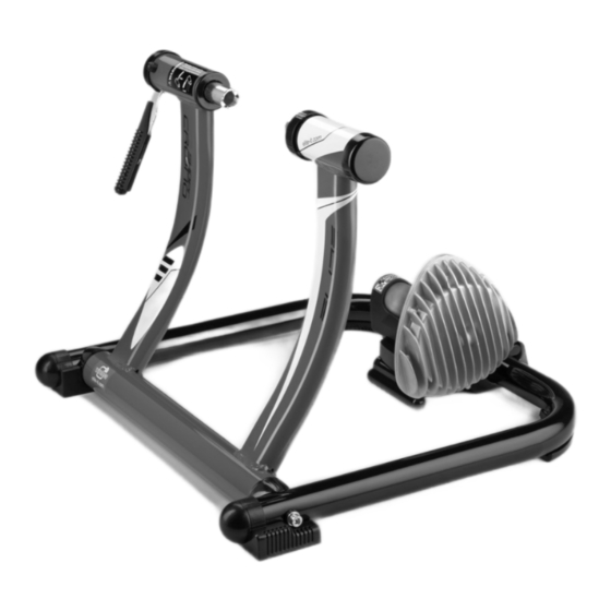
  • Seite 34 All manuals and user guides at all-guides.com MONTAGE DES GESTELLS • Das Gestell öffnen und auf einer Fläche positionieren. • Die untere Stützbasis der Einheit (H), die durch Scharniere mit der oberen Stützbasis (G) verbunden ist, auf das Metallrohr des Gestells montieren (Abb.
  • Seite 35 All manuals and user guides at all-guides.com EINSETZEN DER BATTERIEN • Auf der Basis (G) befinden sich drei Bohrungspaare. verschiedenen Bohrungen nach IN DEN SENDER Raddurchmesser des Fahrrads benutzen: Die Widerstandseinheit aus der Verpackung für Räder mit 29”, hinteres Bohrungspaar (Abb. 6); nehmen und umgekehrt auf einem Tisch oder auf für Räder mit 28”, mittleres Bohrungspaar (Abb.
  • Seite 36 All manuals and user guides at all-guides.com • Die Schrauben (N) vollständig anziehen Schnellspanners in die linke Buchse (C) einführen (Abb. 9). (Abb. 12). Bitte prüfen Sie zur sicheren Befestigung des Hinterrades, dass der Schnellspanner paral- lel zum Boden steht.(Abb. 13). INSTALLIERUNG DES FAHRRADS •...
  • Seite 37 All manuals and user guides at all-guides.com • Wenn der Hebel (F) beginnt, den Schnellspanner in der vorgelegten Arbeitsposition zusammenzudrücken (Abb. 16), müssen Sie den Stift (C) der linken Buchse anziehen (Abb. 17), so dass der Hebel im Innern des vordefinierten Arbeitsbereichs (dem von 30°...
  • Seite 38 All manuals and user guides at all-guides.com NEIN • Bitte stellen Sie sicher, dass der Kopf des Schnellspanners sich innerhalb der halbrunden Sitz des Stifts (C) der linken Buchse befindet (Abb. 24). • Falls das Laufrad nicht mittig auf der Elastogelrolle steht, können Sie über die Langlöcher auf der Bodenplatte die Position der Widerstandseinheit verändern.Dies tun Sie indem...
  • Seite 39 All manuals and user guides at all-guides.com • Sollte die vorherige Einstellung nicht ausrei- chend sein, können Sie die gesamte Basis (G,H) verlagern, indem Sie die Befestigungsschrauben der Basis lockern und in der korrekteren Position wieder anziehen. (Abb. 28, 29 und 30). •...
  • Seite 40 Ziffer verändert werden. Durch EINSTELLUNGEN Drücken der Taste MODE wird der Wert bestätigt Voraussetzung für einen korrekten Gebrauch vom und die nächste Ziffer beginnt zu blinken. Trainer Super Crono Wireless ist die Eingabe der Nachdem alle drei Ziffern vom Gewicht eingestel-...
  • Seite 41 Auf dieser Seite wird der Typ der verwendeten Widerstandseinheit eingestellt. Um den Computer Beim Fahren sind drei verschiedenen Seiten korrekt für den Trainer Super Crono Wireless verfügbar. Jede Seite ist in sechs Bereiche mit einzustellen, muss die Zahl 3 eingegeben wer- verschiedenen Informationen aufgeteilt.
  • Seite 42 ELV.G Überwundener Höhenunterschied. Zeigt an, welcher Höhenunterschied beim Rennen überwunden worden ist. Gesamtstrecke. Strecke, die insgesamt mit dem Trainer Super Crono Wireless gefahren worden ist. TOTAL TIME Gesamtzeit. Zeit, die der Trainer Super Crono insgesamt benützt worden ist. • Für Computer ohne Schalter den Kabel von ENDE VOM RENNEN der Halterung herausziehen.
  • Seite 43 Diese Verbindung bleibt für immer, auch wenn die Batterien ausgetauscht werden. BATTERIEN Der Computer vom Trainer Super Crono Wireless funktioniert mit zwei Batterien vom Typ AA. Wie SYNCHRONISIERUNG lange der Computer damit läuft, hängt davon ab, welche Batterien verwendet werden.
  • Seite 44 Basis der Einheit (G, H) (Abb. 38) oder der obere Display tropft, da sonst die Elektronik beschädigt Teil gedreht wird (Abb. 39). werden kann! • Den Trainer Super Crono Wireless nicht an nas- sen oder feuchten Orten aufbewahren, da sonst die elektronischen Komponenten beschädigt wer-...
  • Seite 45 Gummi sind, können Sie während des Gebrauchs Gummispuren auf dem Fußboden hinterlassen. ABHILFE BEI PROBLEMEN • Beim Gebrauch des Super Crono Wireless Trainer, ist ein leichter Verschleiß der ElastoGel 1 Wenn man beginnt in die Pedale zu treten, Rolle normal. Die im Werk Elite ausgeführten bleiben Geschwindigkeit- und Kraft (Watt)- Tests haben ergeben, dass der Verschleiß...
  • Seite 46 All manuals and user guides at all-guides.com Geschwindigkeit). Der Unterschied zwischen den Widerständen wird einem “virtuellen” Gefälle zugeordnet, das auch von der Geschwindigkeit abhängt; aus diesem Grund verändert sich der Wert Gefälles Veränderung Geschwindigkeit. 6 Der Computer schaltet sich nicht ein. Die im Handel erhältlichen Batterien haben unterschiedliche Abmessungen.
  • Seite 47 Merci d’avoir acheté Super Crono Wireless. N°1 rondelle Ø6 mm (Réf.L) N°1 écrou M6 (Réf.M) Super Crono Wireless est un rouleau d’entraîne- N°1 sachet accessoires unité: ment sans aucun fil. Toutes les informations sont N°1 clé hexagonale transmises par radio de l’unité de transmission à...
  • Seite 48 All manuals and user guides at all-guides.com ASSEMBLAGE DU SUPPORT • Ouvrez le support et positionnez-le sur une surface. • Montez la base inférieure support unité (H) reliée par une charnière à la base supérieure support unité (G) sur le tube métallique du support (fig.1).
  • Seite 49 All manuals and user guides at all-guides.com MONTAGE DES PILES DE L’ÉMETTEUR • Sur la base (G) nous avons trois paires de trous, utilisez les différents trous selon le diamètre de la roue de la bicyclette: Sortir l’unité de résistance de son emballage et la placer renversée sur une table ou sur le sol.
  • Seite 50 All manuals and user guides at all-guides.com • Fixez complètement les vis (N) (fig.9). postérieur dans le fourreau gauche (C) (fig.12). Pour un blocage plus sûr de la bicyclette sur le support, assurez-vous que le levier du déclenche- ment instantané soit tourné à l’horizontale (fig.13).
  • Seite 51 All manuals and user guides at all-guides.com • Si le levier (F) commence à comprimer le déclenchement instantané dans la position de travail anticipée (fig.16), vissez l’axe douille gau- che (C) (fig.17) de manière à ce que le levier commence à travailler à l’intérieur de la zone prédéfinie (celle qui est délimitée de 30°...
  • Seite 52 All manuals and user guides at all-guides.com • Assurez-vous que le levier du déclenchement instantané soit à l’intérieur des déchargement de l’axe douille gauche (C) (fig.24). • Dans le cas où la roue serait trop déplacée par rapport au centre du rouleau (fig.25), déplacez l’unité...
  • Seite 53 All manuals and user guides at all-guides.com • Dans le cas où le réglage précédent ne serait pas suffisant, déplacez toute la base (G,H) en relâchant la vis de fixage de la base et en la blo- quant dans la position la plus correcte (fig.28 , 29 et 30).
  • Seite 54 AFFICHAGES INSTALLATION DE L’ORDINATEUR • Ouvrir le logement des piles qui se trouve sous Pour utiliser correctement Super Crono Wireless le display et introduire les deux piles de type AA il faut d’abord afficher ses propres paramètres. qui se trouvent dans la boîte de l’ordinateur.
  • Seite 55 Pendant la course, trois différents écrans sont stance. Pour préparer correctement l’ordina- disponibles. Chaque écran est divisé en six par- teur pour Super Crono Wireless, entrer le ties avec des informations qui varient selon numéro «3». Ce numéro devrait déjà être établi, l’écran sur lequel on se trouve.
  • Seite 56 Vitesse maximum. Vitesse maximum atteinte pendant la course. ELV.G Gain en élévation. Indique le dénivelé obtenu pendant la course. Distance totale parcourue. Distance totale qui a été parcourue avec Super Crono Wireless. TOTAL TIME Temps total. Temps total pendant lequel on a utilise Super Crono Wireless.
  • Seite 57 été relié. Cette liaison restera pour toujours, même à l’occasion du remplacement des piles. PILES L’ordinateur de Super Crono Wireless utilise deux piles de type AA. L’autonomie du système dépend de la qualité des piles que l’on utilise. Pour optimiser la consommation des piles en phase de stand-by il faut débrancher le fil de...
  • Seite 58 étanche. Attention à ne pas transpirer sur le display, car le circuit électronique pourrait s’en- dommager. • Ne pas garder Super Crono Wireless dans des endroits mouillés ou humides. Ceci pourrait • Pour le transport ou pour réduire l’encombre- endommager les pièces électroniques.
  • Seite 59 0,1 mm, et vu que l’épaisseur totale est de 17.5 une unité de résistance différente de celle de mm, une usure bien supérieure n’empêche pas le Super Crono Wireless. Contrôler que dans la bon fonctionnement du trainer. phase de SET UP (voir chapitre «Affichages»), le •...
  • Seite 60 Le agradecemos que haya escogido Super Crono Wireless. N°1 tuerca M6 (Ref.M) N°1 bolsita de accesorios unidad: El Super Crono Wireless es un rodillo para entre- N°1 llave hexagonal namiento completamente sin cables. Todas las N°2 tornillos M6 x 55 mm (Ref.N) informaciones son transmitidas por radio desde la unidad de transmisión al ordenador sobre una...
  • Seite 61 All manuals and user guides at all-guides.com ENSAMBLAJE SOPORTE • Abrir el soporte y posicionarlo sobre una superficie. • Montar la base inferior soporte unidad (H), ensamblada con bisagra, con la base supe- rior soporte unidad (G) sobre el tubo metálico del soporte (fig.1).
  • Seite 62 All manuals and user guides at all-guides.com MONTAJE BATERÍAS DEL TRANSMISOR • Sobre la base (G) hay tres pares de agujeros, utilizar los diferentes agujeros en base al diáme- tro de la rueda de la bicicleta: Extraer la unidad de resistencia de su embalaje y para ruedas de 29”, par de agujeros posteriores posicionarla vuelta al revés en una mesa o en el (fig.6);...
  • Seite 63 All manuals and user guides at all-guides.com • Apretar completamente los tornillos (N) (fig.9). en el casquillo izquierdo (C) (fig.12). Para un blo- queo más seguro de la bicicleta sobre el soporte, comprobar que la palanca del blocaje rápido esté colocada en sentido horizontal (fig.13).
  • Seite 64 All manuals and user guides at all-guides.com • Si la palanca (F) empieza a comprimir el blocaje rápido en la posición de trabajo anticipada (fig.16), atornillar el perno casquillo izquierdo (C) (fig.17) de tal manera que la palanca empiece a trabajar en el interior del área de predeterminada (aquella delimitada desde 30°...
  • Seite 65 All manuals and user guides at all-guides.com • Comprobar que la palanca del blocaje rápido esté en el interior de las descargas del perno casquillo izquierdo (C) (fig.24). • En caso que la rueda resultase demasiado desplazada con respecto al centro del rodillo (fig.25), mover la unidad de resistencia (A) aflojan- do los tornillos (N) de fijación de la misma y blo- quearlos en la posición más correcta (fig.26 y 27).
  • Seite 66 All manuals and user guides at all-guides.com • En caso que la regulación precedente no fuese suficiente, mover la entera base (G,H) aflojando el tornillo de fijación y bloquearla en la posición más correcta (fig.28 , 29 y 30). • Verificar la estabilidad de la bicicleta tirando y empujando el tubo horizontal del cuadro de la bici y actuando sobre el sillín.
  • Seite 67 REGULACIONES INSTALACIÓN DEL ORDENADOR • Abrir el alojamiento situado bajo el display e Para utilizar correctamente el Super Crono introducir las dos baterías tipo AA que están en la Wireless al principio es preciso introducir y guar- caja del ordenador. Respetar el sentido de la pola- dar los parámetros personales.
  • Seite 68 Durante la carrera están disponibles tres pantallas resistencia. Para configurar correctamente el diferentes. Cada una de ellas está dividida en seis ordenador para el Super Crono Wireless, intro- zonas con informaciones que varían según la ducir el número "3". Este número tendría que pantalla en la que nos hayamos.
  • Seite 69 ELV.G Ganancia en elevación. Indica el desnivel obtenido durante la carrera. Distancia total recorrida. Distancia total que ha sido recorrida con el Super Crono Wireless. TOTAL TIME 3 Tiempo total. Tiempo total en que se ha utilizado el Super Crono Wireless.
  • Seite 70 Dicho acoplamiento permanecerá siempre, inclu- sive cuando se sustituyan las baterías. BATERÍAS El ordenador del Super Crono Wireless utiliza dos baterías de tipo AA. La autonomía del sistema depende de la calidad de las baterías que se utili- zan.
  • Seite 71 Pongan cuidado en no sudar encima del display, porque podría quedar dañado el circuito electrónico. • No guarden el Super Crono Wireless en lugares mojados o húmedos. Podrían quedar dañados los componentes electrónicos. • Si no se utiliza el trainer durante mucho tiempo, aconsejamos sacar las baterías del ordenador y...
  • Seite 72 Super Crono Wireless. Controlar que en la fase de Reclamaciones debidas a uso impropio o negli- SET UP (véase capítulo “Regulaciones”), el número gente, no serán reconocidas como válidas.
  • Seite 73 Hartelijk dank voor het kopen van Super Crono Wireless. 1 Moer M6 (ref. M) 1 Zakje met toebehoren van de eenheid: De Super Crono Wireless is een volledig draadlo- 1 Inbussleutel ze trainingsrol. Alle gegevens worden via radio 2 Schroeven M6x55 mm (ref. N) met een frequentie van 433MHz door de zendeen- 2 Onderlegringen Ø6 mm (ref.
  • Seite 74 All manuals and user guides at all-guides.com MONTEREN VAN DE STANDAARD • Klap de standaard open en zet hem op een ondergrond. • Monteer de onderste steunbasis voor de eenheid (H) scharnierend met de bovenste steunbasis voor de eenheid (G) op de meta- len buis van de standaard ( .
  • Seite 75 All manuals and user guides at all-guides.com DE BATTERIJEN IN DE ZENDER PLAATSEN • In de basis (G) zitten drie paar gaten; gebruik verschillende gaten op basis van de diameter van het wiel van de fiets: Haal de weerstandsunit uit de verpakking en voor wielen van 29”, paar gaten aan de achter- plaats deze ondersteboven op een tafel of een kant (Afb.
  • Seite 76 All manuals and user guides at all-guides.com • Zet de schroeven (N) volledig vast (Afb. 9). sme in de linkerbus (C) (Afb. 12). Om de fiets op een veiligere manier op de standaard vast te zet- ten moet u controleren of de hendel van het snel- loskoppelmechanisme in horizontale richting gedraaid is (Afb.
  • Seite 77 All manuals and user guides at all-guides.com • Als de hendel (F) het snelloskoppelmechanisme in de eerdere werkstand begint in te drukken (fig. 16), moet de linker inbusstift (C) (Afb. 17) zodanig aangedraaid worden dat de hendel in het van tevoren bepaalde werkgebied begint te werken (binnen 30°...
  • Seite 78 All manuals and user guides at all-guides.com • Controleer of de hendel van het snelloskoppel- mechanisme zich binnen de inkepingen van de linker inbusstift (C) bevindt (Afb. 24). • Als het wiel te ver uit het midden van de rol staat (Afb.
  • Seite 79 All manuals and user guides at all-guides.com • Als de vorige afstelling niet voldoende is moet de hele basis (G, H) verplaatst worden door de bevestigingsschroeven van de basis los te draaien waarna de basis in de meest geschikte stand vastgezet moet worden (Afb.
  • Seite 80 INSTELLINGEN batterijhuis. • Bevestig de computer op de houder zoals geto- Om de Super Crono Wireless correct te gebruiken is ond in afbeelding 34. het noodzakelijk dat u vooraf een aantal gegevens invoert. Om deze gegevens in te voeren moet u het SET UP scherm oproepen.
  • Seite 81 Voor het correct het andere scherm over te gaan om de informatie gebruik van de computer van de Super Crono te zien die voor u het meeste belang heeft. Om van Wireless geeft u hier het cijfer ‘3’ in.
  • Seite 82 Maximum snelheid. Grootste snelheid die u ontwikkelde sinds het begin van de sessie. ELV.G Aantal hoogtemeters. Geeft aan hoeveel hoogtemeters u tijdens de sessie overwon. Totale afstand die u al op de Super Crono Wireless fietste. TOTAL TIME Totale tijd die u al op de Super Crono Wireless doorbracht.
  • Seite 83 (ook in ongeveer 200 uur mee. Het is niet mogelijk om geval van meerdere personen die de Super Crono oplaadbare batterijen te gebruiken als ze niet van Wireless gebruiken of in geval van storingen op het 1,5 Volt-type zijn.
  • Seite 84 • Om de fiets te vervoeren of om minder ruimte in • Bewaar de Super Crono Wireless niet in natte of beslag te nemen als de rol niet gebruikt wordt, vochtige omgevingen. Dit kan de electronische wordt geadviseerd om de standaard in te klappen circuits beschadigen.
  • Seite 85 • Claims die te wijten zijn aan oneigenlijk of nala- steld voor een andere weerstandsunit dan die van tig gebruik worden niet in aanmerking genomen. de Super Crono Wireless. Controleer of in het SET Er kan een beetje slijtage van het rubber gedeelte UP-gedeelde weerstandsunit 3 werd ingevoerd.
  • Seite 86 All manuals and user guides at all-guides.com...
  • Seite 87 All manuals and user guides at all-guides.com...
  • Seite 88 All manuals and user guides at all-guides.com NOTES...
  • Seite 89 All manuals and user guides at all-guides.com NOTES...
  • Seite 90 2.Von dem Garantieanspruch ausgeschlossen sind Schäden, die dem ITALIANO 1.In accordo al DL n. 24, del 02/02/2002 e alla direttiva CE 1999/44, ELITE Hersteller nicht zuzuschreiben sind, wie z. B. Fahrlässigkeit und Nachlässigkeit s.r.l. garantisce il proprio prodotto e i materiali impiegati per un periodo di bei der Bedienung und unsachgemässe Behandlung;...
  • Seite 91 Ook als men de gebruiksaanwijzing voor wat betreft het installeren suministradas por Elite s.r.l. por lo que en cada caso se declina todo tipo en gebruik, aangegeven door ELITE s.r.l., niet opvolgt, wordt er in geen de responsabilidad para eventuales daños que directa o indirectamente...
  • Seite 92 All manuals and user guides at all-guides.com ELITE srl - 35014 Fontaniva (PD) - ITALY - Fax +39 049 594 0064 - e-mail: contatto@elite-it.com...