Herunterladen Diese Seite drucken
SMA INVERTER MANAGER Installationsanleitung
Vorschau ausblenden Andere Handbücher für INVERTER MANAGER:

Werbung

Verfügbare Sprachen
  • DE

Verfügbare Sprachen

Installation Manual
SMA INVERTER MANAGER /
SMA DIGITAL I/O BOX
1 Information on this Document
1.1 Validity
This document is valid for the SMA Inverter Manager and
for the SMA Digital I/O Box.
1.2 Target Group
The activities described in this document must only be
performed by qualified persons. Qualified persons must
have the following skills:
• Training in the installation and commissioning of
electrical devices
• Training in how to deal with the dangers and risks
associated with installing and using electrical devices
and installations
• Training in the installation and configuration of IT
systems
• Knowledge of how an inverter works and is operated
• Knowledge of all applicable laws, standards and
directives
• Knowledge of and compliance with this document and
all safety information and warning messages
1.3 Symbols
Symbol
IMVIOBOX-IA-xx-10 | 139R0136 | Version 1.0
Explanation
Indicates a hazardous situation
which, if not avoided, will result
in death or serious injury
Indicates a hazardous situation
which, if not avoided, can result
in death or serious injury
Indicates a hazardous situation
which, if not avoided, can result
in minor or moderate injury
Indicates a situation which, if
not avoided, can result in
property damage
Symbol
1.4 Nomenclature
Complete designation
SMA Inverter Manager
SMA Digital I/O Box
SMA Solar Technology AG SMA
SMA America, LLC
SMA Solar Technology
Canada Inc.
Explanation
Information that is important for
a specific topic or goal, but is
not safety-relevant
Indicates a requirement for
meeting a specific goal
Desired result
A problem that might occur
Designation in this
document
Inverter Manager
I/O Box
ENGLISH

Werbung

loading

Inhaltszusammenfassung für SMA INVERTER MANAGER

  • Seite 1 Symbol Explanation Information that is important for 1.1 Validity a specific topic or goal, but is This document is valid for the SMA Inverter Manager and not safety-relevant for the SMA Digital I/O Box. ☐ Indicates a requirement for meeting a specific goal 1.2 Target Group...
  • Seite 2 The Inverter Manager receives the specifications from the I/O Box and controls all inverters in the system accordingly. The Inverter Manager and the I/O Box must only be used indoors and must only be operated with the SMA inverter Sunny Tripower 60 (STP 60-10 and STP 60-US-10).
  • Seite 3 3.2.2 Option 2: Mounting on Top-Hat Rail Inverter Manager Damage to the products and cables due to moisture The Inverter Manager and the I/O Box are not protected against splash water. Consequently, moisture can penetrate the device and damage the products and cables.
  • Seite 4 3  Inverter Manager SMA Solar Technology AG / SMA America, LLC 3.3 Connection to the Inverter Manager 3.3.1 Safety Information Danger to life due to electric shock Lethal voltages are present at the connection point of the utility grid. • Disconnect the connection point from voltage sources and ensure that the connection point is voltage-free.
  • Seite 5 • Ground the enclosure of the product. ETx- TRD(0)- ERx+ TRD(1)+ Procedure: TRD(2)+ To connect the Inverter Manager to the voltage supply, perform the following actions in the specified order. TRD(2)- • Connect the grounding conductor to the ERx- TRD(1)- Inverter Manager.
  • Seite 6 (P1-P2) green ports P1-P2 Real-Time Clock The real-time clock of the Inverter Manager is powered by No data reception via serial a lithium battery. We strongly recommend not to change the ports P1-P2 lithium battery without the assistance of qualified service...
  • Seite 7 SMA Solar Technology AG / SMA America, LLC 3  Inverter Manager 3.6 Technical Data Interfaces Maximum cable length for 1,200 m (4,000 ft) Voltage Supply RS485 cabling Input voltage 9 VDC to 36 VDC System monitoring Sunny Portal, SunSpec Power consumption <...
  • Seite 8 Contact your distributor if the scope of delivery is incomplete or damaged. 4.2.2 Option 2: Mounting on Top-Hat Rail Figure2: Components included in the scope of delivery of the SMA Digital I/O Box Position Quantit Designation SMA Digital I/O Box 4.3 Connection to the I/O Box...
  • Seite 9 SMA Solar Technology AG / SMA America, LLC 4  SMA Digital I/O Box Connection of a Signal Source (10 V to 30 V) Position Designation with Digital Output Signals Maintain the default setting: X1 = 1, X10 = COM0 Connection of the Inverter Manager 10 V ...
  • Seite 10 4  SMA Digital I/O Box SMA Solar Technology AG / SMA America, LLC 4.3.5 LED Signals of the I/O Box System Data Operating altitude 2,000 m Status Explanation Standards and UL 508, CE, FCC Class A Power Glowing The I/O Box is in operation.
  • Seite 11 Symbol Erklärung Dokument Warnhinweis, dessen Nichtbeachtung zu 1.1  Gültigkeitsbereich Sachschäden führen kann Dieses Dokument gilt für den SMA Inverter Manager und Information, die für ein die SMA Digital I/O Box. bestimmtes Thema oder Ziel wichtig, aber nicht 1.2  Zielgruppe sicherheitsrelevant ist Die in diesem Dokument beschriebenen Tätigkeiten dürfen ☐...
  • Seite 12 Der Inverter Manager empfängt die Vorgaben von der I/O Box und steuert entsprechend alle Wechselrichter in der Anlage. Der Inverter Manager und die I/O Box dürfen nur im Innenbereich eingesetzt und ausschließlich mit dem SMA Wechselrichter Sunny Tripower 60 (STP 60-10 und STP 60-US-10) betrieben werden.
  • Seite 13 Der Inverter Manager und die I/O Box sind nicht spritzwassergeschützt. Dadurch kann Feuchtigkeit eindringen und die Produkte und Leitungen beschädigen. • Den Inverter Manager und die I/O Box müssen in trockener Umgebung, z. B. im Innenraum oder in einem spritzwassergeschütztem Gehäuse (Schutzart: mindestens IP54 (NEMA 3R)) installiert werden.
  • Seite 14 3    Inverter Manager SMA Solar Technology AG / SMA America, LLC 3.3  Anschluss an den Inverter Manager 3.3.1  Sicherheitshinweis Lebensgefahr durch Stromschlag An der Anschluss-Stelle des öffentlichen Stromnetzes liegen lebensgefährliche Spannungen an. • Die Anschluss-Stelle freischalten und sicherstellen, dass die Anschluss-Stelle frei von Spannung ist.
  • Seite 15 
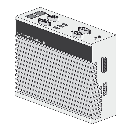
Ansicht oben an der Buchse für den Stromanschluss. Pin-Belegung der seriellen Schnittstelle (RS485): Vorgehen: • Den Inverter Manager erden. Dazu den Erdungsleiter an der Erdungsschraube des Inverter Managers anschließen. Eine ordentliche Erdung und der korrekte Kabelverlauf tragen dazu bei, mögliche Störaussendungen aufgrund elektromagnetischer...
  • Seite 16 3    Inverter Manager SMA Solar Technology AG / SMA America, LLC Netzteil anschließen Service-Personal zu wechseln. Sollte ein Batteriewechsel erforderlich werden, wenden Sie sich an den Service (Kontaktdaten siehe www.SMA-Solar.com). Wenn die Batterie durch einen falschen Batterietyp ersetzt wird, besteht Explosionsgefahr.
  • Seite 17 SMA Solar Technology AG / SMA America, LLC 3    Inverter Manager 3.6  Technische Daten Schnittstellen Maximale Kabellänge für 1.200 m (4.000 ft) Spannungsversorgung RS485-Verkabelung Eingangsspannung 9 VDC … 36 VDC Anlagenüberwachung Sunny Portal, SunSpec Leistungsaufnahme < 20 W Modbus TCP Maximaler Leiterquerschnitt 1,3 mm²...
  • Seite 18 Dadurch kann Feuchtigkeit eindringen und die Produkte und Leitungen beschädigen. Position Bezeichnung • Den Inverter Manager und die I/O Box müssen in Digitale Eingänge für den Anschluss einer trockener Umgebung, z. B. im Innenraum oder in Signalquelle (Eingänge DI0 bis DI5 können einem spritzwassergeschütztem Gehäuse (Schutzart:...
  • Seite 19 SMA Solar Technology AG / SMA America, LLC 4    SMA Digital I/O Box 4.3.2  Inverter Manager anschließen 4.3.4  I/O Box an Spannungsversorgung anschließen Pin-Belegung der Anschlussklemme (RS485): Verbinden Sie die 12 bis 36 V DC Anschlussleitung mit der Anschlussklemme für die Spannungsversorgung. Schließen Sie die Erdung der Anschlussleitung an die Klemme „V-“...
  • Seite 20 4    SMA Digital I/O Box SMA Solar Technology AG / SMA America, LLC Zustand Erklärung Port 2 Gelb blinkt Daten werden gesendet oder empfangen. 4.4  Technische Daten Systemdaten Stromversorgung 24 VDC nominal, 12 VDC … 36 VDC Verkabelung I/O Kabel max. 4 AWG...
  • Seite 21 Advertencia que, de no ser observada, puede causar 1.1 Área de validez daños materiales Este documento es válido para el SMA Inverter Manager y Información importante para la SMA Digital I/O Box. un tema u objetivo concretos, aunque no relevante para la 1.2 Grupo de destinatarios...
  • Seite 22 El Inverter Manager recibe las especificaciones de la I/O Box y controla en consecuencia todos los inversores de la planta. El Inverter Manager y la I/O Box deben emplearse únicamente en interiores y con los inversores de SMA Sunny Tripower 60 (STP 60-10 y STP 60-US-10).
  • Seite 23 3.2.2 Variante 2: Montaje en carril Daños en el producto y los cables debido a la penetración de humedad El Inverter Manager y la I/O Box no están protegidos contra las salpicaduras de agua. Podría penetrar humedad y dañar los productos y cables.
  • Seite 24 3  Inverter Manager SMA Solar Technology AG / SMA America, LLC 3.3 Conexión al Inverter Manager 3.3.1 Indicación de seguridad Peligro de muerte por descarga eléctrica En el punto de conexión de la red pública hay tensiones eléctricas que pueden causar la muerte.
  • Seite 25 Asignación de patillas de la interfaz serial (RS485): Procedimiento: • Ponga a tierra el Inverter Manager. Para ello, conecte el conductor de protección al tornillo de puesta a tierra del Inverter Manager. Que la toma a tierra sea...
  • Seite 26 Reloj en tiempo real (P1-P2) en verde de puertos en serie P1-P2 El reloj en tiempo real del Inverter Manager funciona con Apagado Sin recepción de datos a una batería de litio. Le recomendamos encarecidamente no través de puertos en serie cambiar la batería de litio sin la ayuda de personal del...
  • Seite 27 SMA Solar Technology AG / SMA America, LLC 3  Inverter Manager 3.6 Datos técnicos Interfaces Longitud máxima del cable 1 200 m (4 000 ft) Suministro de tensión para el cableado RS485 Tensión de entrada 9 V CC … 36 V CC Monitorización de la...
  • Seite 28 4.2 Montaje de la I/O Box COM0 Daños en el producto y los cables debido a la penetración de humedad El Inverter Manager y la I/O Box no están protegidos COM0 contra las salpicaduras de agua. Podría penetrar humedad y dañar los productos y cables.
  • Seite 29 SMA Solar Technology AG / SMA America, LLC 4  SMA Digital I/O Box Conexión de una fuente de señal (10 V … 30V) Posición Denominación con señales de salida digitales Entradas digitales para la conexión a una fuente de señal (pueden ocuparse las entradas de DI0 a DI5;...
  • Seite 30 4  SMA Digital I/O Box SMA Solar Technology AG / SMA America, LLC 4.3.5 Señales led de la I/O Box Datos del sistema Altitud de funcionamiento < 2 000 m Estado Explicación Estándares y certificaciones UL 508, CE, FCC clase A...
  • Seite 31 Informazioni importanti per un determinato obiettivo o 1.1 Ambito di validità argomento, non rilevanti tuttavia dal punto di vista della Il presente documento vale per SMA Inverter Manager e sicurezza SMA Digital I/O Box. ☐ Condizioni preliminari 1.2 Destinatari...
  • Seite 32 Manager. I/O Box riceve i comandi per la gestione di rete mediante segnali digitali e trasmette i set point a Inverter Manager. Inverter Manager riceve i set point da I/O Box e regola di conseguenza tutti gli inverter dell’impianto. Inverter Manager e I/O Box possono essere impiegati solo in...
  • Seite 33 Manager Danneggiamento di prodotti e linee a causa dell’umidità Inverter Manager e I/O Box non sono protetti contro gli spruzzi d’acqua. L’umidità potrebbe pertanto penetrare all’interno e danneggiare prodotti e linee. • Inverter Manager e I/O Box devono essere installati in un ambiente asciutto, ad es.
  • Seite 34 3  Inverter Manager SMA Solar Technology AG / SMA America, LLC 3.3 Collegamento a Inverter Manager 3.3.1 Avvertenza di sicurezza Pericolo di morte per folgorazione Nel punto di connessione alla rete pubblica sono presenti tensioni potenzialmente letali. • Disinserire il punto di connessione e accertarsi che non sia sotto tensione.
  • Seite 35 Assegnazione dei pin dell’interfaccia seriale (RS485): presa per il collegamento elettrico. Procedura: • Mettere a terra Inverter Manager collegando il conduttore di protezione alla vite di messa a terra dello stesso. Una messa a terra regolamentare e un corretto percorso dei cavi contribuiscono a limitare possibili disturbi dovuti a interferenze elettromagnetiche.
  • Seite 36 Ricezione di dati tramite le Orologio con tempo reale (P1-P2) nte verde porte seriali P1-P2 L’orologio con tempo reale di Inverter Manager è Spento Nessuna ricezione di dati alimentato da una batteria al litio. Raccomandiamo tramite le porte seriali P1-P2 caldamente di non sostituire tale batteria senza l’aiuto di...
  • Seite 37 SMA Solar Technology AG / SMA America, LLC 3  Inverter Manager 3.6 Dati tecnici Interfacce Lunghezza massima dei 100 m (328 ft) Alimentazione di tensione cavi per il collegamento Tensione d’ingresso 9 VCC … 36 VCC Ethernet Assorbimento di potenza <...
  • Seite 38 4.2 Montaggio di I/O Box COM0 Danneggiamento di prodotti e linee a causa dell’umidità Inverter Manager e I/O Box non sono protetti contro gli COM0 spruzzi d’acqua. L’umidità potrebbe pertanto penetrare all’interno e danneggiare prodotti e linee. • Inverter Manager e I/O Box devono essere installati in un ambiente asciutto, ad es.
  • Seite 39 SMA Solar Technology AG / SMA America, LLC 4  SMA Digital I/O Box 4.3.3 Collegamento della sorgente di Posizione Denominazione segnali Ingressi digitali per il collegamento di una sorgente di segnali (gli ingressi da DI0 a Collegamento di una sorgente di segnali con DI5 possono essere occupati, tutti gli altri contatto relè...
  • Seite 40 4  SMA Digital I/O Box SMA Solar Technology AG / SMA America, LLC 4.3.4 Collegamento di I/O Box Stato Spiegazione all’alimentazione di tensione Port 1 Lampeggiante È in corso l’invio o la ricezione verde di dati. Collegate la linea da 12 a 36 V CC al morsetto dell’alimentazione di tensione.
  • Seite 41 Symbol Objaśnienie niniejszego dokumentu Ostrzeżenie, którego 1.1 Zakres obowiązywania zignorowanie może Niniejszy dokument dotyczy urządzeń SMA Inverter spowodować Manager i SMA Digital I/O Box. średnie lub lekkie obrażenia ciała. 1.2 Grupa docelowa Ostrzeżenie, Opisane w niniejszym dokumencie czynności mogą którego wykonywać...
  • Seite 42 W przypadku stwierdzenia monitorowania i sterowania maks. 42 falownikami firmy niekompletności lub uszkodzenia urządzenia należy SMA typu STP 60-10 i STP 60-US-10 w rozproszonych skontaktować się ze sprzedawcą produktu. oraz dużych instalacjach fotowoltaicznych o mocy do 2,5 I/O Box jest wielofunkcyjnym interfejsem przeznaczonym do 1 urządzenia Inverter Manager.
  • Seite 43 3.2.2 Wariant 2: montaż na szynie Manager Zagrożenie uszkodzeniem produktów i przewodów przez wilgoć Inverter Manager i I/O Box nie są chronione przed kroplami wody padającymi pod dowolnym kątem. Wskutek tego do wnętrza produktów i przewodów może się przedostać wilgoć.
  • Seite 44 3  Inverter Manager SMA Solar Technology AG / SMA America, LLC 3.3 Podłączenie do urządzenia Inverter Manager 3.3.1 Wskazówka dotycząca bezpieczeństwa Zagrożenie życia na skutek porażenia prądem W miejscu przyłączenia do publicznej sieci elektroenergetycznej występują niebezpieczne dla życia napięcia. • Przyłącze należy odłączyć spod napięcia i zapewnić...
  • Seite 45 Ground" - SG) znajduje się w górnej części niniejszego rysunku obok gniazda zasilania prądem elektrycznym. Sposób postępowania: • Uziemnij Inverter Manager. W tym celu podłącz przewód uziemiający do śruby uziemienia urządzenia Inverter Manager. Prawidłowe uziemienie urządzenia i prawidłowo poprowadzony kabel pozwalają...
  • Seite 46 3  Inverter Manager SMA Solar Technology AG / SMA America, LLC Podłączenie zasilacza serwisantowi. Jeśli wymiana baterii będzie konieczna, prosimy skontaktować się z serwisem (dane kontaktowe patrz www.SMA-Solar.com). Zastosowanie nieprawidłowego typu baterii stwarza zagrożenie eksplozją. 3.4 Połączenie urządzenia Firma SMA zaleca stosowanie zasilacza sieciowego dostępnego jako wyposażenie dodatkowe (numer...
  • Seite 47 SMA Solar Technology AG / SMA America, LLC 3  Inverter Manager Dioda LED Stan Objaśnienie Złącza Rx1, Rx2 Pulsuje Odbiór danych poprzez Złącze do podłączenia Tryb SunSpec, RS485 (P1-P2) kolorem złącza szeregowe P1/P2. SMA Digital I/O Box (D-Sub 9) zielonym.
  • Seite 48 4.2 Montaż urządzenia I/O Box COM0 Zagrożenie uszkodzeniem produktów i przewodów przez wilgoć Inverter Manager i I/O Box nie są chronione przed COM0 kroplami wody padającymi pod dowolnym kątem. Wskutek tego do wnętrza produktów i przewodów może się przedostać wilgoć.
  • Seite 49 SMA Solar Technology AG / SMA America, LLC 4  SMA Digital I/O Box 4.3.3 Podłączenie nadajnika sygnału Pozycja Nazwa Wejścia cyfrowe do podłączenia Podłączenie nadajnika sygnału z nadajnika sygnału (można wykorzystać bezpotencjałowym zestykiem wejścia od DI0 do DI5, pozostałe są...
  • Seite 50 4  SMA Digital I/O Box SMA Solar Technology AG / SMA America, LLC 4.3.4 Podłączanie urządzenia I/O Dioda Stan Objaśnienie Box do napięcia zasilającego Dioda Świeci się System jest gotowy do pracy. Podłącz przewód zasilający napięciem od 12 do 36 V DC...
  • Seite 51 SMA Solar Technology AG / SMA America, LLC 4  SMA Digital I/O Box 4.4 Dane techniczne Dane systemu Zasilanie energią 24 V DC znamionowe, elektryczną 12 V DC … 36 V DC Okablowanie Kabel I/O maks. 4 AWG Wymiary 27,8 mm x 124 mm x 84 mm (1.09 x 4.88 x 3.31 in)

Diese Anleitung auch für:

Digital i/o box