Audiotec Fischer match UP 1FX Bedienungsanleitung
1-kanal upgrade-subwoofer-verstärker mit integrierter frequenzweiche und 1 ohm stabilität

Verwandte Anleitungen für Audiotec Fischer match UP 1FX


Inhaltszusammenfassung für Audiotec Fischer match UP 1FX
- Seite 1 UP 1FX U P G R A D E 1-Kanal Upgrade-Subwoofer-Verstärker mit integrierter Frequenzweiche und 1 Ohm Stabilität 1-channel upgrade subwoofer amplifier with integrated crossover and 1 Ohm stability...
-
Seite 2: Allgemeine Hinweise
Verarbeitung MATCH Verstärkers. und eine überzeugende Anwendung ausgereifter Technologien aus. Audiotec Fischer setzt mit der UP 1FX neue Maßstäbe im Bereich der Verstärkertechnik. Viel Freude an diesem Produkt wünscht Ihnen das Dabei profitieren Sie als Kunde direkt von unserer Team von mehr als 30-jährigen Erfahrung in der Forschung... -
Seite 3: Anschluss- Und Bedienelemente
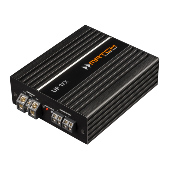
Anschluss- und Bedienelemente Highlevel-Lautsprechereingänge Filter-Modus-Schalter Seite 5, Punkt 3 Seite 5, Punkt 4 Tiefpassfilter-Regler (LPF) Anschluss Stromversorgung & Remote Seite 7, Punkt 1 Seite 5, Punkt 5 Fernbedienungs-Eingang Kontroll LED für die internen Sicherungen Seite 7, Punkt 2 Seite 7, Punkt 4 Clipping LED Status LED Seite 7, Punkt 3... -
Seite 4: Hardware-Konfiguration
Hardware-Konfiguration Konfigurieren Sie den MATCH UP 1FX Verstär- risierten MATCH Fachhändler zu wenden. ker in der nachfolgenden Reihenfolge Wenn Sie unsicher sind, empfehlen wir, den Jumper auf den „High Voltage Range“ (Cinch Achtung: Für die Durchführung der nachfolgenden 1 - 6 V / Highlevel 6 - 32 V) einzustellen, um Schritte werden Spezialwerkzeuge und Fachwissen mögliche Schäden am Gerät zu vermeiden. - Seite 5 2. Anschluss des Lowlevel-Vorverstärkerein- Frequenzweiche zu umgehen. Mit Hilfe des gangs X-Over-Schalters (Seite 3, Punkt 1) kann die Der Vorverstärkereingang (Line Input) kann mit Funktion aktiviert bzw. deaktiviert werden. einem entsprechenden Kabel an den RCA / DirectDSP: Die interne Frequenzweiche ist Cinch-Ausgang der Signalquelle (bspw.
- Seite 6 Hardware-Konfiguration REM: Der Remote-Eingang dient zum Ein- und Sollte die Signalquelle eine niedrigere Aus- Ausschalten der UP 1FX. Dieser wird mit dem gangsspannung liefern, kann die Eingangs- Remote-Ausgang der unmittelbar vorgeschal- empfindlichkeit über den Gain-Regler stufenlos angehoben werden. teten Komponente, welche das Eingangssignal für die UP 1FX liefert, verbunden.
-
Seite 7: Weitere Funktionen
von Plus und Minus hat einen Totalverlust der 8. Filtereinstellungen Basswiedergabe zur Folge. Der Pluspol ist bei Sofern Sie die DirectDSP-Funktion (siehe den meisten Lautsprechern gekennzeichnet. Seite 5, Punkt 4) aktiviert haben, müssen die Die Impedanz darf 1 Ohm nicht unterschreitenn, Übernahmefrequenzen für den Subsonic bzw. - Seite 8 Konfigurationsbeispiele Hinweis: Sofern Sie die DirectDSP-Funktion aktiviert haben, müssen Sie die Übernahmefrequenzen für den Subsonic bzw. Tiefpass mit Hilfe eines vorgeschalteten DSPs oder DSP-Verstärkers einge- stellt werden. Mono-Subwooferanwendung Subwoofer mit einer Schwingspule (Single Voice Coil) RMS-Ausgangsleistung ≤ 1% THD+N: 1 x 4 Ohm: 350 Watt 1 x 2 Ohm: 600 Watt 1 x 1 Ohm: 900 Watt Parallelbetrieb...
- Seite 9 Reihenbetrieb Zwei identische Subwoofer mit einer Schwingspule (Single Voice Coil) oder ein Subwoofer mit Doppelschwingspule (Dual Voice Coil) werden in Reihe geschaltet. Hinweis: Die Reihenschaltung von zwei Schwingspulen führt zur Verdopplung der Impedanz! RMS-Ausgangsleistung ≤ 1% THD+N: entsprechen einer Zwei Subwoofer 1 x 2 Ohm Zwei Subwoofer mit einer...
-
Seite 10: Technische Daten
Technische Daten Leistung RMS (≤ 1% THD+N) - @ 4 Ohm ..............1 x 350 Watt - @ 2 Ohm ..............1 x 600 Watt - @ 1 Ohm ..............1 x 900 Watt* Max. Leistung ............... Bis zu 1.000 Watt RMS @ 1 Ohm Verstärkertechnologie ...........Class D Eingänge .............. - Seite 20 Audiotec Fischer GmbH Hünegräben 26 · 57392 Schmallenberg · Germany Tel.: +49 2972 9788 0 · Fax: +49 2972 9788 88 E-mail: match@audiotec-fischer.com · Internet: www.audiotec-fischer.com Made in China...