Audiotec Fischer MATCH M 5DSP MK2 Anleitung
5-kanal miniatur-verstärker mit integriertem dsp
Inhaltsverzeichnis
Verfügbare Sprachen
Verfügbare Sprachen
Inhaltsverzeichnis

Verwandte Anleitungen für Audiotec Fischer MATCH M 5DSP MK2


Inhaltszusammenfassung für Audiotec Fischer MATCH M 5DSP MK2
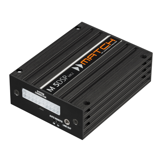
- Seite 1 M 5DSP micro 5-Kanal Miniatur-Verstärker mit integriertem DSP...
-
Seite 2: Allgemeine Hinweise
M 5DSP MK2 neue Maßstäbe im Bereich der Verstärkertechnik. Dabei Viel Freude an diesem Produkt wünscht Ihnen das als 30-jährigen Erfahrung in der Forschung und AUDIOTEC FISCHER Allgemeine Hinweise Allgemeines zum Einbau von MATCH-Kompo- können. nenten Allgemeines zum Anschluss des M 5DSP MK2 Um alle Möglichkeiten des Produktes optimal aus-... -
Seite 3: Anschluss- Und Bedienelemente
Resetten des Gerätes. Control Input Remote In / Out Multifunktionsanschluss – dient Der Remote-Eingang dient zum Einschalten Anschluss einer Fernbedienung der M 5DSP MK2. Der Remote-Ausgang weiterem MATCH M 5DSP MK2 Zubehör. dient zum Einschalten weiterer Verstärker bei... -
Seite 4: Subwoofer Output
Anschluss weiterer Verstärker zu Diese Buchse dient zum Anschluss des mitgeliefer- ten Kabelbaums. Verwenden Sie zur Verbindung 4 Subwoofer Output des MATCH M 5DSP MK2 mit dem Originalradio ausschließlich den mitgelieferten Kabelbaum oder MATCH Plug & Play Subwoofers, wie beispiels- gramm. -
Seite 5: Status Led
Speicher gelöscht! Anschließend wird dies durch Setup muss über die DSP PC-Tool Software einge- ein durchgehendes rotes Leuchten und grünes spielt werden oder schalten Sie auf einen Speicher- schnelles Dauerblinken der Status LED angezeigt. Achtung: der MATCH M 5DSP MK2 keine Audiosignale mehr... -
Seite 6: Spezielle Features Der M 5Dsp Mk2
Inbetriebnahme und Funktionen 9 Optical Input Control Input Optischer Eingang im SPDIF-Format für den An- Dieser Multifunktionsanschluss dient zum An- Die „Sampling Rate“ dieses Eingangs muss zwi- spielsweise einer Fernbedienung mit deren Hilfe schen 12 - 96 kHz liegen. Das Eingangssignal wird automatisch an die interne Abtastrate angepasst. -
Seite 7: Umschaltung Der Leistungsmodi
Umschaltung der Leistungsmodi HighPower- / MidPower-Modus Im folgenden Abschnitt nun die wichtigsten Schritte den „HighPower“-Modus für maximale Performance 1. Schließen Sie den Verstärker mit dem bei- “MidPower”-Modus reduzierter liegenden USB-Kabel an den Computer an. Ausgangsleistung und geringerer Stromaufnahme Wenn Sie längere Distanzen zu überbrü- für Plug &... -
Seite 8: Einbau Und Installation
Einbau und Installation Abb. 1: Pinbelegung System Connector SYSTEM AUTO REMOTE Lautsprecherausgang hinten rechts (-) Lautsprecherausgang hinten links (-) Masse Masse Abb. 2: Subwoofer Anschlusskabel 8-poliger Molex Stecker – zum Anschluss 2-poliger Molex Stecker – zum Anschluss an eines MATCH Plug & Play Subwoofers den Subwoofer Output der M 5DSP MK2... - Seite 9 Der MATCH M 5DSP MK2 Verstärker wird wie darf 4 Ohm nicht unterschreiten, da sonst die nachfolgend beschrieben an das Autoradio angeschlossen. Achtung: Für die Durchführung der nachfolgenden 3. Anschluss einer digitalen Signalquelle Schritte werden Spezialwerkzeuge und Fachwis- sen benötigt. Um Anschlussfehler und Beschädi- an den Optical Input des Verstärkers ange-...
- Seite 10 Einbau und Installation Das Massekabel (schwarz / gleicher Quer- Molex Stecker des Subwooferkabels mit dem Subwoofer Output des Verstärkers. des Kfz-Chassis oder direkt an dem Minuspol der Autobatterie angeschlossen werden. 5. Anschluss des Remote-Eingangs Der Remote-Eingang (Remote In) muss mit woofers oder Center-Lautsprechers: Subwooferkabels (C).
-
Seite 11: Anschluss Mit Hilfe Des Pp-Iso Kabels
Anschluss mit Hilfe des PP-ISO Kabels Um die Installation des M 5DSP MK2 an ein Werks- Fahrzeugs: kann der Verstärker auch mit Hilfe eines optional erhältlichen PP-ISO Kabels (2,2 m Version - dieses Kabel kann der Verstärker sowohl mit nal-Kabelbaums ist in der Regel mit max. 20 A Strom als auch mit den Lautsprechersignalen des abgesichert. - Seite 12 Anschluss mit Hilfe des PP-ISO Kabels kabels an das Bordnetz muss die Autobat- Hinweis: MOST-Bus terie abgeklemmt werden. Bei einigen Fahrzeugen kann es notwendig sein, die kabel (gelb Abb. 4 / min. 4 mm²) ist am Pluspol der Batterie anzuschließen. Die Plus- schlussstecker auszulösen und stattdessen in den 30 cm Radio-Stecker eines ISO-Adapters einzustecken.
- Seite 13 Abb. 4: Diese Seite des Kabelbaums wird direkt an die Batterie angeschlossen. Dafür werden die dafür Schwarze Leitung: Masse-Leitung zum Anschluss an den Minuspol der Autobatterie oder zum An- schluss an einen Massepunkt des Kfz-Chassis. Anschließend ist es wichtig, beide Leitungen einzeln zu isolieren.
- Seite 14 Der MATCH M 5DSP MK2 Verstärker bietet ein- ted Bass Processing“, den „StageXpander“, den „ RealCenter“ und mehr. men, müssen in der DSP PC-Tool Software Einstel- Hinweis: Das Center Processing wird ausschließ- lich auf den Ausgangskanal E angewendet. ner RealCenter- und ClarityXpander-Funktion Um die RealCenter- und ClarityXpander-Funktion für...
- Seite 15 Signalrouting F & G: 5. Abschließend legen Sie noch durch Setzen eines Hakens fest, auf welchen Ausgangskanal bzw. welche Ausgangskanäle sich das Bass Processing auswirken soll. 3. Wiederholen Sie das Routing für alle genutzten Routing-Matrizen. eines Hakens. ACO Plattform-Features tet die ACO-Plattform des M 5DSP MK2 zusätzlich den.
-
Seite 16: Technische Daten
Technische Daten Ausgangsleistung RMS / Max. - @ 4 Ohm (Front / Rear Kanäle) ........4 x 60 / 120 Watt (HighPower-Modus) 4 x 35 / 70 Watt (MidPower-Modus) - Subwooferausgang an 4 Ohm……………………………1 x 90 / 180 Watt (High- & MidPower-Modus) - Subwooferausgang an 2 Ohm……………………………1 x 160 / 320 Watt (High- &... - Seite 32 Audiotec Fischer GmbH Hünegräben 26 · 57392 Schmallenberg · Germany...