Audiotec Fischer M116005 Bedienungsanleitung
6-kanal upgrade-verstärker mit integriertem 7-kanal 64 bit dsp für universelle anwendungen

Verwandte Anleitungen für Audiotec Fischer M116005


Inhaltszusammenfassung für Audiotec Fischer M116005
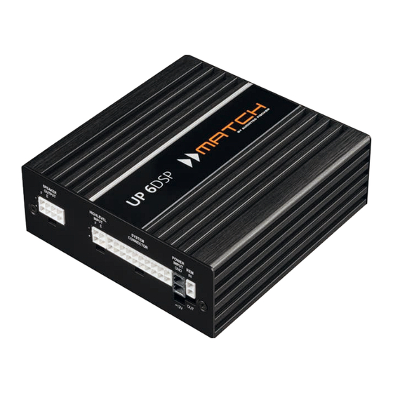
- Seite 1 UP 6DSP U P G R A D E 6-Kanal Upgrade-Verstärker mit integriertem 7-Kanal 64 Bit DSP für universelle Anwendungen 6-channel upgrade amplifier with integrated 7-channel 64 Bit DSP for universal applications...
-
Seite 2: Allgemeine Hinweise
Viel Freude an diesem Produkt wünscht Ihnen das als Kunde direkt von unserer mehr als 30-jährigen Team von Erfahrung in der Forschung und Entwicklung von Audiokomponenten. AUDIOTEC FISCHER Allgemeine Hinweise Allgemeines zum Einbau von MATCH-Kompo- den. Achten Sie bitte darauf, dass sich solche Teile nenten auch in der doppelten Wandverkleidung verbergen können. -
Seite 3: Anschluss- Und Bedienelemente
Anschluss- und Bedienelemente Control Taster Lautsprecherausgänge E & F Seite 10, Punkt 2 Seite 6, Punkt 3 Highlevel-Lautsprechereingäge E & F Auto Remote-Schalter Seite 6, Punkt 2 Seite 7, Punkt 5 System Connector Eingang SCP (Smart Control Port) Seite 6, Punkt 1 Seite 11, Punkt 3 Anschluss Stromversorgung Optischer Digitaleingang... - Seite 4 Hardware-Konfiguration Abb. 1: Pinbelegung UP 6DSP System Connector Highlevel-Lautsprechereingang hinten links (-) / C Highlevel-Lautsprechereingang hinten links (+) / C Highlevel-Lautsprechereingang vorne links (-) / A Highlevel-Lautsprechereingang vorne links (+) / A Highlevel-Lautsprechereingang vorne rechts (-) / B Highlevel-Lautsprechereingang vorne rechts (+) / B Highlevel-Lautsprechereingang hinten rechts (-) / D Highlevel-Lautsprechereingang hinten rechts (+) / D Lautsprecherausgang hinten rechts (-) / D...
- Seite 5 Abb. 2: Übersicht Anschlusskabel Power Input Anschlusskabel (+12V / GND) System Connector Anschlusskabel Speaker Output E - F Anschlusskabel Highlevel Input E - F Anschlusskabel Remote (REM IN / OUT) Anschlusskabel...
-
Seite 6: Hardware-Konfiguration
Hardware-Konfiguration Konfigurieren Sie den MATCH UP 6DSP in der Die Impedanz pro Kanal darf 4 Ohm nicht nachfolgenden Reihenfolge unterschreiten, da sonst die Schutzschal- tung des Verstärkers aktiviert wird. Achtung: Für die Durchführung der nachfolgenden Achtung: Verwenden Sie zum Anschluss Schritte werden Spezialwerkzeuge und Fachwissen ausschließlich das mitgelieferte System benötigt. - Seite 7 schließlich das mitgelieferte Anschlusskabel mit Remote Schalters (Seite 3, Punkt 8) kann die dem 8-poligen Stecker und den offenen Kabel- automatische Einschaltung über die Highlevel- enden (Seite 5, Abb. 2) oder einen passenden Lautsprechereingänge deaktiviert werden. Dies Kabelbaum aus dem MATCH Zubehörpro- sollte vorgenommen werden, wenn es bei- gramm.
- Seite 8 Hardware-Konfiguration Out angeschlossenen Verstärkers. Verbinden Homepage und laden die aktuellste Software Sie dazu den Remote-Ausgang der UP 6DSP Version des DSP PC-Tools herunter. Es ist mit dem Remote-Eingang des Verstärkers, um ratsam, regelmäßig nach Updates der Software diesen über den internen DSP störungsfrei ein- zu schauen, damit das Gerät immer auf dem und auszuschalten.
- Seite 9 Max imalpegel liefert, sollte die Eingangsemp- bis die Clipping Anzeige erlischt. findlichkeit vorsichtig angehoben werden. Hinweis: Muten Sie während dieser Prozedur die Signalausgänge der UP 6DSP. 7. Erhöhen Sie die Eingangsempfindlichkeit bis Zur Anpassung der Eingangsempfindlichkeit die Clipping Anzeige aufleuchtet. Schieben führen Sie bitte die folgenden Schritte durch: Sie nun den Regler zurück bis die Clipping 1.
-
Seite 10: Weitere Funktionen
Hardware-Konfiguration 12. Optional: Anschluss des Vorverstärkeraus- 13. Sound Tuning gangs Nun können Sie Ihr Sound Setup erstellen. In- Der Line Out ist ein Mono-Vorverstärker-Signal- formationen rund um das Sound Tuning finden Sie in unserer umfangreichen Knowledge Base ausgang zum Anschluss eines zusätzlichen Verstärkers. - Seite 11 3. SCP (Smart Control Port) Dieser Multifunktionseingang dient zum An- schluss von MATCH Zubehörprodukten, wie beispielsweise einer Fernbedienung, mit deren Hilfe diverse Funktionen des Verstärkers ge- steuert werden können. SCP-to-Control Input Adapter Die Funktionalität muss je nach Typ der Fern- bedienung zuerst im „Device Configuration Menu“...
- Seite 12 Konfigurationsbeispiele Beispiel 2: 6-Kanal 1 zu 1 Kanalrouting (IOR) z.B.: Vorne 2-Wege passiv / Hinten 2-Wege passiv / zwei Subwoofer mit einer Schwingspule (1 x 2 Ohm) Vom Werks- Eingänge Ausgänge Zu den Lautsprechern verstärker Front L High Input A Amp Out A Front L Full –...
- Seite 13 Virtual Channel Processing (VCP) Die MATCH UP 6DSP bietet neben dem Standard Routing das Virtual Channel Processing (VCP), ein mehrstufiges Signalverarbeitungs-Konzept, welches die perfekte Konfiguration komplexer Soundsysteme ermöglicht und somit ganz neue Möglichkeiten des Klangtunings eröffnet. Das VCP erweitert den bisherigen Umfang des Gerätes um eine neue Ebene an prozessierten Kanälen, welche sich zwischen den Ein- und Ausgängen befindet.
-
Seite 14: Konfiguration Einer Subwoofer-Fernbedienung
Konfiguration einer Subwoofer-Fernbedienung Zur Konfiguration einer Subwoofer-Fernbedienung müssen im DSP PC-Tool bestimmte Einstellungen vor- genommen werden. Zunächst muss die entsprechende Fernbedienung im Tab „Erweiterte Einstellungen“ im DCM Menü der DSP PC-Tool Software aktiviert und je nach Modell konfiguriert werden. Bei nicht aktiviertem VCP ist die Subwoofer-Fernbedienung bei der UP 6DSP fest den Ausgangskanälen E und F zugeordnet. - Seite 15 ACO Plattform-Features Neben den einzigartigen DSP-Sound effekten bie- Remote Output Configuration tet die ACO-Plattform der UP 6DSP zusätzlich eine An dieser Stelle kann festgelegt werden, ob der Vielzahl an System-Features. Remote-Ausgang, der die angeschlossenen End- Im DCM Menü der DSP PC-Tool Software können stufen ein- bzw.
-
Seite 16: Einbau Einer Match Extension Card
Einbau einer MATCH Extension Card Der MATCH UP 6DSP Verstärker kann durch die 6. Achten Sie auf den richtigen Sitz des MEC Mo- Montage einer MATCH Extension Card (MEC) um duls und darauf, dass alle Kontaktstifte vollstän- weitere Schnittstellen wie beispielsweise einem dig im Sockel stecken. -
Seite 17: Technische Daten
Technische Daten Leistung RMS - Kanal A - D ..............4 x 65 @ 4 Ohm - Sub Out E - F ..............2 x 90 Watt @ 4 Ohm 2 x 160 Watt @ 2 Ohm Verstärkertechnologie ............Class GD Eingänge ................ -
Seite 18: Garantiehinweis
Die Bluetooth Wortmarke und die Logos sind eingetragene Warenzeichen der Bluetooth SIG, Inc. und ® jegliche Nutzung dieser Marken durch die Audiotec Fischer GmbH geschieht unter Lizenz. Andere Han- delsmarken und Handelsnamen gehören den jeweiligen Inhabern. Hinweise zur Entsorgung Dieses Symbol bedeutet, dass das Produkt nicht über den Hausmüll entsorgt werden darf, sondern bei einer entsprechenden Sammelstelle zum Recycling abgegeben werden muss.