
Verwandte Anleitungen für gilles.tooling FXR- A01


Inhaltszusammenfassung für gilles.tooling FXR- A01
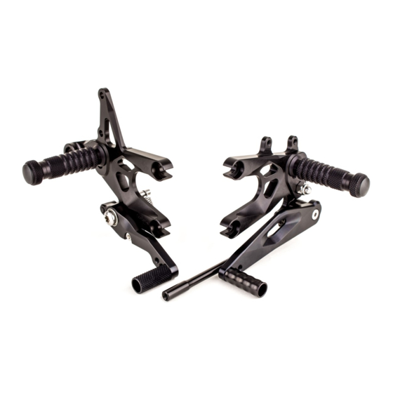
- Seite 1 FXR- A01 rearsets Zertifikat Certificate Anbauanleitung Owners manual Für Modelle mit und ohne Schaltautomat for versions with and without quickshifter www.gillestooling.com info@gillestooling.com...
-
Seite 2: Sicherheitshinweise
Sicherheitshinweise Sicherheitshinweise Sicherheitshinweise Sicherheitshinweise Sicherheitshinweise Sicherheitshinweise Sicherheitshinweise Sicherheitshinweise Diese Anbauanleitung ist sorgfältig und vollständig vor Beginn der Einbauarbeiten durchzulesen. Diese Anbauanleitung ist sorgfältig und vollständig vor Beginn der Einbauarbeiten durchzulesen. Diese Anbauanleitung ist sorgfältig und vollständig vor Beginn der Einbauarbeiten durchzulesen. Diese Anbauanleitung ist sorgfältig und vollständig vor Beginn der Einbauarbeiten durchzulesen. -
Seite 3: Safety Instructions
Safety instructions Safety instructions Safety instructions Safety instructions Safety instructions Safety instructions Safety instructions Safety instructions You must read these Installation Instructions carefully and make sure you understand everything You must read these Installation Instructions carefully and make sure you understand everything You must read these Installation Instructions carefully and make sure you understand everything You must read these Installation Instructions carefully and make sure you understand everything You must read these Installation Instructions carefully and make sure you understand everything... - Seite 4 surface pos. article no. description material qty. treatment FXR-GL-A01-* left basic plate EN AW-2017 anodized gear lever UL01L-* EN AW-7075 anodized bearing US-27-* gear lever EN AW-2017 anodized USW14-* gear shaft EN AW-7075 anodized USW09-* gear shaft EN AW-7075 anodized gear lever toe UTR-08-* EN AW-2007...
- Seite 5 fxr-A01-rechts POS-NR. Artikelnummer_GT Description MENGE FXR-GR-A01-* right basic plate UB-20-* brake lever UAH-11-* exhaust holder UF-12-* footrest brake lever toe UTR-09-* piece FXR-EX-01 excenter BR-05 brake bolt DS 20-8-6 spacer DS 12-6-6 collar 7 702 856 plug 7 702 868 spring fixing pin RZ-115NI spring brake lever...
-
Seite 6: Vormontage Links
FXR-A01 Vormontage Links Subassembly left hand side USW09 heel guard M8x25-912 20Nm M6x20-912 7 702 856 SA02 10Nm Quickshifter FXR-A01 USW14 Vormontage Rechts Subassembly right hand side M6x20-912 M8x25-912 10Nm 20Nm M5x16-912 7 702 856 RZ115NI ULS8,4 M8x25-7985 20Nm... - Seite 7 FXR-A01 Anbauanleitung/Manual Links: -Original Rastenanlage,Fersenschützer und Schalthebel demontieren(1). -Vorsichtige Handhabung des Schaltauto-maten beachten. Left hand side: -Remove original footrest system, heel guard and gear lever(1). -Handle the quick shifter with care, while disassembling and reassembling. -Grundplatte GL-A01 mit Schrauben M8x25-7985 und Distanzen DS20-8-8 an Rahmen befestigen(2).
- Seite 8 FXR-A01 Anbauanleitung/Manual -Gewindestift M6x30-913 an Schaltassisten min. 6 3 Quickshifter mm einschrauben und mit Kontermutter M6x30-913 M6-934 sichern(3). Anzugsdrehmoment: 10 Nm Schalltwelle USW14 einsetzen, Schalthebelhöhe einstellen und mit Kontermuttern M6-934 / -L sichern(4). Anzugsdrehmoment: 10 Nm M6-934 -Install threaded bar M6-913 a min. of 6mm into quick shifter and secure with nut M6-934(3).
- Seite 9 FXR-A01 Anbauanleitung/Manual Rechts: -Rastenanlage,Bremszylinder und Stopplichtschalter demontieren(5). Right hand side: -Remove original rearsets, brake cylinder and stoplight switch(5). -OEM Gummi mit Buchse in Auspuffhalter einsetzen. -Grundplatten GR-A01 mit Schrauben M8x25-7985 und Distanz DS20-8-6 an Rahmen befestigen(6). Anzugsdrehmoment: 20 Nm M8x25-7985 DS20-8-6 -Insert OEM rubber and collar into exhaust holder UAH-11.
- Seite 10 FXR-A01 Anbauanleitung/Manual -Screw OEM piston bolt(8) into OEM-brake adapter until the brake cylinder bolts M6x25-7380 together with OEM heelguard fit easily into the master cylinder (8+9). M6x25-7380 DS12-6-6 Special note: -Brake cylinder must not be pressed when fitting the bolts from the brake master cylinder !!! -Secure piston bolt with nut after adjusting.
- Seite 11 FXR-A01 Anbauanleitung/Manual Hinweis: -Zur Bremshebelhöheneinstellung muss der Bremszylinder demontiert sein(13). -Die Bremshebelhöheneinstellung erfolgt durch drehen des Excenters am Bremshebel im vorgegebenen min. und max. Bereich(14+15). -Der Excenter darf nicht über diesen Bereich hinaus gedreht werden. Special note: To adjust the brake lever height the master M5x16-912 cylinder bolts must be removed(13).
- Seite 12 FXR-A01 Packzettel/Packing Slip Pos. Description Part-No. Qty. OK 27 22 28 15 24 31 35 31 35 bolt M6x25-7380-VA 22 28 31 35 22 28 31 35 bolt M8x25-7985-VA bolt M6x20-912-VA bolt M8x25-912-VA washer ULS8,4 spacer DS 12-6-6 spacer DS 20-8-6 spacer DS 20-8-8 plug...