Herunterladen Inhalt Inhalt Diese Seite drucken
Inhaltsverzeichnis

Werbung

Verfügbare Sprachen

Verfügbare Sprachen

CMP-402 ● CMP-403
v1.01 11.09.2023
1
34
67
100

Werbung

Inhaltsverzeichnis
loading

Inhaltszusammenfassung für Sonel CMP-402

  • Seite 1 INSTRUKCJA OBSŁUGI USER MANUAL MANUAL DE USO BEDIENUNGSANLEITUNG CMP-402 ● CMP-403 v1.01 11.09.2023...
  • Seite 3: Instrukcja Obsługi

    INSTRUKCJA OBSŁUGI CYFROWY MIERNIK CĘGOWY CMP-402 ● CMP-403 Wersja 1.01 11.09.2023...
  • Seite 4 Multimetr True RMS CMP-402 / 403 przeznaczony jest do pomiaru napięcia stałego i przemiennego, prądu stałego ( ) i prze- miennego, rezystancji, pojemności elektrycznej, częstotliwości, cy- klu roboczego (wypełnienia) i temperatury, a także testowania diod oraz ciągłości. Do najważniejszych cech przyrządu CMP-402 / 403 należą: ...
  • Seite 5: Inhaltsverzeichnis

    Przycisk RANGE .............. 23 Przycisk MODE/VFD ............23 6.3.1 Zmiana trybu pomiarowego ........23 6.3.2 Funkcja VFD .............. 23 Przycisk PEAK/INRUSH ........... 24 6.4.1 Funkcja PEAK MAX/PEAK MIN ......... 24 6.4.2 Funkcja INRUSH ............24 CMP-402 ● CMP-403 – INSTRUKCJA OBSŁUGI...
  • Seite 6 7 Wymiana baterii ............26 8 Utrzymanie i konserwacja ......... 27 9 Magazynowanie ............28 10 Rozbiórka i utylizacja ..........28 11 Specyfikacja ............... 29 11.1 Dane techniczne............... 29 11.2 Dane eksploatacyjne ............32 12 Serwis ................. 33 CMP-402 ● CMP-403 – INSTRUKCJA OBSŁUGI...
  • Seite 7: Wstęp

    źródłem poważ- nego niebezpieczeństwa dla użytkownika.  Miernik CMP-402 / 403 może być używany jedynie przez wy- kwalifikowane osoby, posiadające odpowiednie uprawnienia do prac przy instalacjach elektrycznych. Posługiwanie się...
  • Seite 8: Bezpieczeństwo

     miernika, który uległ uszkodzeniu i jest całkowicie lub czę- ściowo niesprawny  przewodów z uszkodzoną izolacją  miernika przechowywanego zbyt długo w złych warunkach (np. zawilgoconego)  naprawy mogą być wykonywane wyłącznie przez autoryzowa- ny serwis. CMP-402 ● CMP-403 – INSTRUKCJA OBSŁUGI...
  • Seite 9: Symbole Bezpieczeństwa

    że w warunkach normalnego użytkowania istnieje możliwość wystąpienia niebezpiecznych napięć. II klasa ochronności – izolacja podwójna Tak oznaczone gniazda nie mogą być podłączone do obwodu, gdzie napięcie względem ziemi przekracza maksymalne napięcie bezpieczne przyrządu. CMP-402 ● CMP-403 – INSTRUKCJA OBSŁUGI...
  • Seite 10: Przygotowanie Miernika Do Pracy

    Użytkując miernik należy pamiętać, by:  rozładować kondensatory w badanych źródłach zasilania,  odłączyć zasilanie podczas pomiarów rezystancji i testowa- nia diod,  wyłączyć miernik i odłączyć przewody pomiarowe przed demon- tażem tylnej pokrywy celem wymiany baterii. CMP-402 ● CMP-403 – INSTRUKCJA OBSŁUGI...
  • Seite 11 Jest to normalne zjawisko, które wynika z czułości wejścia o dużej rezystancji wejściowej. Po podłączeniu do obwodu odczyt ustabilizuje się i miernik poda prawidłową wartość. CMP-402 ● CMP-403 – INSTRUKCJA OBSŁUGI...
  • Seite 12: Opis Funkcjonalny

    4 Opis funkcjonalny 4.1 Gniazda i funkcje pomiarowe CMP-402 ● CMP-403 – INSTRUKCJA OBSŁUGI...
  • Seite 13  – pomiar napięcia stałego  Hz% VFD – pomiar napięcia przemiennego, pomiar częstotliwo- ści i cyklu roboczego, pomiar prądu i napięcia za falownikiem, przekształtnikiem częstotliwości, w układzie VFD  OFF – miernik wyłączony CMP-402 ● CMP-403 – INSTRUKCJA OBSŁUGI...
  • Seite 14 Wyświetla wartość szczytową mierzonego sygnału (nacisnąć krótko) Wyświetla prąd rozruchu (nacisnąć krótko) Gniazdo pomiarowe COM Wejście pomiarowe wspólne dla wszystkich funkcji pomiarowych oprócz pomiaru prądu. Gniazdo pomiarowe VΩCAP Hz%Temp Wejście pomiarowe dla wszystkich pomiarów oprócz pomiaru prądu. CMP-402 ● CMP-403 – INSTRUKCJA OBSŁUGI...
  • Seite 15: Wyświetlacz

    / µ / m / k / M Przedrostek wielokrotności jednostki pomiaru Pomiar napięcia Pomiar prądu Pomiar pojemności Ω Pomiar rezystancji Pomiar częstotliwości Pomiar cyklu roboczego – Ujemna wartość odczytu Przekroczenie zakresu pomiaru CMP-402 ● CMP-403 – INSTRUKCJA OBSŁUGI...
  • Seite 16: Przewody

    Podłączanie nieodpowiednich przewodów grozi pora- żeniem prądem elektrycznym lub możliwością wystą- pienia błędów pomiarowych.  Sondy pomiarowe wyposażone są w dodatkowe, demon- towalne osłony ostrzy.  Sondy należy przechowywać wyłącznie w miejscu do te- go przeznaczonym. CMP-402 ● CMP-403 – INSTRUKCJA OBSŁUGI...
  • Seite 17: Pomiary

     odczytać wynik pomiaru na wyświetlaczu. Jeżeli mierzony jest prąd DC i miernik nie jest zapięty na mierzony obwód, a mimo to wskazuje niezerową wartość pomiaru, należy wyzerować wskazanie miernika poprzez naciśnięcie i przytrzymanie przycisku REL CMP-402 ● CMP-403 – INSTRUKCJA OBSŁUGI...
  • Seite 18: Bezdotykowy Wskaźnik Napięcia

     Rodzaj i grubość izolacji, odległość od źródła napięcia, przewody ekranowane oraz inne czynniki mogą wpłynąć na skuteczność działania wskaźnika. W przypadku braku pewności co do wyniku testu, stwierdź obecność napię- cia w inny sposób. CMP-402 ● CMP-403 – INSTRUKCJA OBSŁUGI...
  • Seite 19: Pomiar Napięcia

     nacisnąć przycisk MODE/VFD w celu wyświetlenia na wyświetla- czu symbolu Hz,  podłączyć czarny przewód pomiarowy do gniazda COM, a czer- wony do gniazda VΩCAP Hz%Temp,  przyłożyć ostrza sond do punktów pomiarowych,  odczytać wynik pomiaru na wyświetlaczu. CMP-402 ● CMP-403 – INSTRUKCJA OBSŁUGI...
  • Seite 20: Pomiar % Cyklu Roboczego (Współczynnika Wypełnienia Impulsu)

    VΩCAP Hz%Temp,  przyłożyć ostrza sond do punktów pomiarowych; najlepiej jest roz- łączyć jedną stronę testowanego elementu, tak aby pozostała część obwodu nie zakłócała odczytu wartości rezystancji,  odczytać wynik pomiaru na wyświetlaczu. CMP-402 ● CMP-403 – INSTRUKCJA OBSŁUGI...
  • Seite 21: Test Ciągłości Obwodu

     Dla typowej diody prostowniczej krzemowej wynosi ono ok. 0,7 V, a dla diody germanowej ok. 0,3 V.  Dla diod LED małej mocy typowa wartość napięcia mieści się w zakresie 1,2…5,0 V w zależności od koloru. CMP-402 ● CMP-403 – INSTRUKCJA OBSŁUGI...
  • Seite 22: Pomiar Pojemności

     nacisnąć przycisk MODE/VFD, aby wyświetlić nF na wyświetlaczu,  podłączyć czarny przewód pomiarowy do gniazda COM, a czer- wony do gniazda VΩCAP Hz%Temp,  przyłożyć ostrza sond do testowanego kondensatora,  odczytać wynik pomiaru na wyświetlaczu. CMP-402 ● CMP-403 – INSTRUKCJA OBSŁUGI...
  • Seite 23: Pomiar Temperatury

    Kontakt głowicy z mierzoną częścią testowanego urządzenia należy utrzymywać, dopóki odczyt się nie ustabilizuje,  odczytać wynik pomiaru na wyświetlaczu,  po zakończeniu pomiarów odłączyć sondę od miernika. UWAGA! Ryzyko poparzenia. Sonda temperaturowa nagrzewa się, przyjmując temperaturę mierzonego obiektu. CMP-402 ● CMP-403 – INSTRUKCJA OBSŁUGI...
  • Seite 24: Funkcje Specjalne

     Funkcja jest niedostępna dla testu diody, ciągłości, czę- stotliwości i cyklu roboczego. Podświetlenie wyświetlacza 6.1.2 Naciśnięcie i przytrzymanie przycisku REL przez 2 sekundy powoduje włączenie lub wyłączenie funkcji podświetlenia wyświetlacza. CMP-402 ● CMP-403 – INSTRUKCJA OBSŁUGI...
  • Seite 25: Przycisk Range

    VFD, należy:  ustawić przełącznik obrotowy w pozycji pomiaru napięcia lub prądu,  nacisnąć i przytrzymać przycisk MODE/VFD, aż pojawi się sym- bol „VFD”. Aby wyłączyć tryb, nacisnąć nacisnąć i przytrzymać przycisk MODE/VFD. CMP-402 ● CMP-403 – INSTRUKCJA OBSŁUGI...
  • Seite 26: Przycisk Peak/Inrush

     W czasie gdy funkcja INRUSH jest aktywna, nie działa automa- tyczne dobieranie zakresów, dlatego zaleca się uruchamiać funkcję dopiero po podłączenia przewodów do punktu pomiaro- wego. Uruchomienie funkcji INRUSH przed podłączeniem mier- nika do punktu mierzonego może powodować wyświetlanie symboli przekroczenia zakresu. CMP-402 ● CMP-403 – INSTRUKCJA OBSŁUGI...
  • Seite 27: Przycisk H

     poczekać, aż miernik osiągnie gotowość do pomiaru,  puścić przycisk MODE/VFD. Gdy automatyczne wyłączenie jest nieaktywne, na wyświetlaczu nie widnieje APO. Każde przejście pokrętła przez pozycję OFF przy nienaciśniętym przycisku MODE/VFD ponownie uaktywnia funkcję automatycznego wyłączenia. CMP-402 ● CMP-403 – INSTRUKCJA OBSŁUGI...
  • Seite 28: Wymiana Baterii

    Aby uniknąć porażenia elektrycznego nie należy uży- wać miernika, jeżeli pokrywa baterii nie znajduje się na swoim miejscu i nie jest prawidłowo zamocowana. Miernik CMP-402 / 403 jest zasilany z trzech baterii LR03 AAA 1,5 V. Zaleca się stosowanie baterii alkalicznych. Aby wymienić baterie, należy: ...
  • Seite 29: Utrzymanie I Konserwacja

    6. JEŻELI MIERNIK MA BYĆ PRZECHOWYWANY DŁUŻEJ NIŻ 60 DNI, należy wyjąć z niego baterie i trzymać je oddzielnie. Układ elektroniczny miernika nie wymaga konserwacji. CMP-402 ● CMP-403 – INSTRUKCJA OBSŁUGI...
  • Seite 30: Magazynowanie

    Ustawą o zużytym sprzęcie elektrycznym i elektronicz- nym. Przed przekazaniem sprzętu do punktu zbiórki nie należy sa- modzielnie demontować żadnych części z tego sprzętu. Należy przestrzegać lokalnych przepisów dotyczących wyrzu- cania opakowań, zużytych baterii i akumulatorów. CMP-402 ● CMP-403 – INSTRUKCJA OBSŁUGI...
  • Seite 31: Specyfikacja

    Wszystkie napięcia AC są określone w przedziale 5%…100% zakresu  Impedancja wejściowa: 10 MΩ  Zakres częstotliwości: 50 Hz…1000 Hz  Zabezpieczenie przed przeciążeniem 1000 V DC/AC RMS  Zakres napięć AC dla funkcji VFD: 100 V…600 V CMP-402 ● CMP-403 – INSTRUKCJA OBSŁUGI...
  • Seite 32  (3,0% w.m. + 5 cyfr) 99,99 µF 0,01 µF 999,9 µF 0,1 µF 9,999 mF 0,001 mF  (5,0% w.m. + 5 cyfr) 99,99 mF 0,01 mF  Zabezpieczenie przed przeciążeniem 300 V DC/AC RMS CMP-402 ● CMP-403 – INSTRUKCJA OBSŁUGI...
  • Seite 33 Dokładność -20,0…+1000C 0,1 lub 1C ± (3% w.m. + 3C) -4,0…+1832F 0,1 lub 1F ± (3% w.m. + 5F)  Dokładność sondy temperaturowej nie jest uwzględniana  Zabezpieczenie przed przeciążeniem 300 V DC/AC RMS CMP-402 ● CMP-403 – INSTRUKCJA OBSŁUGI...
  • Seite 34: Dane Eksploatacyjne

    ....................odczyt 4000 ze wskaźnikami funkcji wymiary ......................... 220 x 80 x 39 mm masa miernika ▪ CMP-402 ..........................266 g ▪ CMP-402 (bez baterii) ......................230 g ▪ CMP-403 ..........................270 g ▪ CMP-403 (bez baterii) ......................234 g temperatura pracy ......................+5…+40C wilgotność...
  • Seite 35: Serwis

    58-100 Świdnica tel. +48 74 884 10 53 (Biuro Obsługi Klienta) e-mail: bok@sonel.pl internet: www.sonel.pl UWAGA! Do prowadzenia napraw serwisowych upoważniony jest je- dynie producent. Wyprodukowano w Chińskiej Republice Ludowej na zlecenie SONEL S.A. CMP-402 ● CMP-403 – INSTRUKCJA OBSŁUGI...
  • Seite 36: User Manual

    USER MANUAL DIGITAL CLAMP METER CMP-402 ● CMP-403 Version 1.01 11.09.2023...
  • Seite 37 CMP-402 / 403 True RMS multimeter is intended for measuring di- rect and alternating voltage, direct ( ) and alternating cur- rent, resistance, capacitance, frequency, duty cycle (filling) and temperature and for testing diodes and circuit continuity. The most important features of CMP-402 / 403 include: ...
  • Seite 38 Button MODE/VFD ............56 6.3.1 Changing the measurement mode ......56 6.3.2 VFD function .............. 56 PEAK/INRUSH button ............57 6.4.1 PEAK MAX/PEAK MIN function ......... 57 6.4.2 INRUSH function ............57 Button H ..............58 CMP-402 ● CMP-403 – USER MANUAL...
  • Seite 39 8 Maintenance and care ..........60 9 Storage ............... 61 10 Dismantling and disposal ......... 61 11 Specifications ............62 11.1 Technical data ..............62 11.2 Operating data ..............65 12 Service ................ 66 CMP-402 ● CMP-403 – USER MANUAL...
  • Seite 40: Introduction

    Indication of possible problems is preceded by symbol WARNING  CMP-402 / 403 meter is designed to measure the AC/DC current and voltage, frequency, resistance, capacitance, as well as to test the circuit continuity and diodes. Any...
  • Seite 41: Safety

     a device with damaged insulation of test leads,  a meter stored for an excessive period of time in disadvan- tageous conditions (e.g. excessive humidity).  repairs may be carried out only by an authorised service point. CMP-402 ● CMP-403 – USER MANUAL...
  • Seite 42: Safety Symbols

    Protection class II – double insulation Terminals with this marking cannot be connected to a circuit where the voltage to ground exceeds the maximum safe voltage of the device. CMP-402 ● CMP-403 – USER MANUAL...
  • Seite 43: Preparing The Meter For Operation

     discharge capacitors in the tested power sources,  disconnect the power supply when measuring the resistance and diode tests,  turn off the meter and disconnect test leads before removing the back cover to replace the batteries. CMP-402 ● CMP-403 – USER MANUAL...
  • Seite 44 This is a normal phenomenon, which results from the input sensitivi- ty with high input resistance. When connected to a circuit, the read-out will stabilize and the meter will provide the cor- rect value. CMP-402 ● CMP-403 – USER MANUAL...
  • Seite 45: Functional Description

    4 Functional description 4.1 Measuring terminals and functions CMP-402 ● CMP-403 – USER MANUAL...
  • Seite 46 Hz% VFD – measurement of alternating voltage, measurement of frequency and duty cycle, measurement of current and voltage behind the inverter, frequency converter, in the VFD system  OFF – the meter is switched off CMP-402 ● CMP-403 – USER MANUAL...
  • Seite 47 Displays peak value of the measured signal (press briefly) Displays the starting current (press briefly) COM measuring terminal Measuring input, common for all measuring functions excluding current. Measurement terminal VΩCAP Hz%Temp Measuring input for measurements other than current measurement. CMP-402 ● CMP-403 – USER MANUAL...
  • Seite 48: Display

    / µ / m / k / M The prefix of multiple measurement unit Voltage measurement Current measurement Measurement of capacitance Ω Measurement of resistance Measurement of frequency Duty cycle measurement – Negative read-out value Exceeded measurement range CMP-402 ● CMP-403 – USER MANUAL...
  • Seite 49: Leads

    WARNING Connecting wrong leads may cause electric shock or measurement errors.  The probes are equipped with additional removable tip guards.  The probes must be stored in a designated area. CMP-402 ● CMP-403 – USER MANUAL...
  • Seite 50: Measurements

     read the measurement result on the display. If DC current is measured and the meter is not attached to the tested circuit, but it still indicates a non-zero value, then you must reset it by pressing and holding button. CMP-402 ● CMP-403 – USER MANUAL...
  • Seite 51: Non-Contact Voltage Detector

     The type and thickness of the insulation, distance from the power source, shielded cables and other factors may affect the operation of the tester. If you are unsure about the test result, check the presence of voltage in a differ- ent way. CMP-402 ● CMP-403 – USER MANUAL...
  • Seite 52: Voltage Measurement

     connect black test lead to COM terminal, and red test lead to VΩCAP Hz%Temp terminal,  contact the tips of test probes to the points of measurement,  read the measurement result on the display. CMP-402 ● CMP-403 – USER MANUAL...
  • Seite 53: Measurement % Of Duty Cycle (Pulse Filling Indicator)

     read the measurement result on the display. CMP-402 ● CMP-403 – USER MANUAL...
  • Seite 54: Circuit Continuity Test

     For a typical silicon rectifier diode, it is approx. 0.7 V, and for a germanium diode it is approx. 0.3 V  For LEDs with a low power, typical voltage value is in the range of 1.2…5.0 V depending on the colour. CMP-402 ● CMP-403 – USER MANUAL...
  • Seite 55: Measurement Of Capacitance

     press MODE/VFD button to display nF on the screen,  connect black test lead to COM terminal, and red test lead to VΩCAP Hz%Temp terminal,  contact the probe tips to the tested capacitor,  read the measurement result on the display. CMP-402 ● CMP-403 – USER MANUAL...
  • Seite 56: Temperature Measurement

     after completing the measurements, disconnect the probe from the meter. CAUTION! Risk of burns. The temperature probe heats up, adapting to the temperature of tested object. CMP-402 ● CMP-403 – USER MANUAL...
  • Seite 57: Special Features

     This function is not available for diode test, continuity test and duty cycle. 6.1.2 Display backlight Pressing and holding REL button for 2 seconds will turn ON/OFF the display backlight function. CMP-402 ● CMP-403 – USER MANUAL...
  • Seite 58: Range Button

     set the rotary switch to the voltage or current measurement position,  press and hold the MODE/VFD button until the "VFD" symbol appears. To disable the mode, press and hold the MODE/VFD button. CMP-402 ● CMP-403 – USER MANUAL...
  • Seite 59: Peak/Inrush Button

     While INRUSH is active, autoranging is disabled, therfore it is advised to start the function after connecting test leads to the measurement point. Running INRUSH before that may cause overrange symbols to appear. CMP-402 ● CMP-403 – USER MANUAL...
  • Seite 60: Button H

     release MODE/VFD button. When the automatic shutdown is de- activated, the display does not show APO. Each pass of the rotary switch through "OFF" position with non-pressed MODE/VFD button, will activate again the Au- to-Off function. CMP-402 ● CMP-403 – USER MANUAL...
  • Seite 61: Replacing The Batteries

    To avoid electric shock, do not use the meter if the bat- tery compartment cover is not in place or is not properly fastened. CMP-402 / 403 is powered by by three LR03 AAA 1.5 V batter- ies. It is recommended to use alkaline batteries. To replace the batteries: ...
  • Seite 62: Maintenance And Care

    6. IF THE METER IS TO BE STORED FOR LONGER THAN 60 DAYS, remove the batteries and keep them separately. The electronic system of the meter does not require maintenance. CMP-402 ● CMP-403 – USER MANUAL...
  • Seite 63: Storage

    Before the equipment is sent to a collection point, do not dis- mantle any elements. Observe local regulations concerning disposal of packages, waste batteries and accumulators. CMP-402 ● CMP-403 – USER MANUAL...
  • Seite 64: Specifications

    All AC voltage ranges are specified from 5% to 100% of range  Input impedance: 10 MΩ  Frequency range: 50 Hz…1000 Hz  Overload protection: 1000 V DC/AC RMS  AC voltage range for VFD function: 100 V…600 V CMP-402 ● CMP-403 – USER MANUAL...
  • Seite 65  (3.0% m.v. + 5 digits) 99.99 µF 0.01 µF 999.9 µF 0.1 µF 9.999 mF 0.001 mF  (5.0% m.v. + 5 digits) 99.99 mF 0.01 mF  Overload protection: 300 V DC/AC RMS CMP-402 ● CMP-403 – USER MANUAL...
  • Seite 66 0.1 or 1C ± (3% m.v. + 3C) -4.0…+1832F 0.1 or 1F ± (3% m.v. + 5F)  The accuracy of the temperature probe is not taken into account  Overload protection: 300 V DC/AC RMS CMP-402 ● CMP-403 – USER MANUAL...
  • Seite 67: Operating Data

    ....................4000 counts with function indicators dimensions ......................220 x 80 x 39 mm meter weight ▪ CMP-402 ..........................266 g ▪ CMP-402 (without batteries) ....................230 g ▪ CMP-403 ..........................270 g ▪ CMP-403 (without batteries) ....................234 g operating temperature ......................+5..+40C operating humidity ....
  • Seite 68: Service

    The provider of guarantee and post-guarantee services is: SONEL S.A. Wokulskiego 11 58-100 Świdnica Poland tel. +48 74 884 10 53 (Customer Service) e-mail: customerservice@sonel.com web page: www.sonel.com CAUTION! Service repairs must be performed only by the manufacturer. CMP-402 ● CMP-403 – USER MANUAL...
  • Seite 69: Manual De Uso

    MANUAL DE USO MEDIDOR DE PINZA DIGITAL CMP-402 ● CMP-403 Versión 1.01 11.09.2023...
  • Seite 70 El multímetro True RMS CMP-402 / 403 está diseñado para medir la tensión continua y alterna, corriente continua ( ) y alterna, resistencia, capacidad eléctrica, frecuencia, ciclo de trabajo (de llenado), y temperatura y prueba de diodos y de la continuidad.
  • Seite 71 Botón RANGE ..............89 Botón MODE/VFD ............89 Cambio del modo de medición ........89 6.3.1 Función VFD .............. 89 6.3.2 Botón PEAK/INRUSH ............90 Función PEAK MAX/PEAK MIN ......... 90 6.4.1 Función INRUSH............90 6.4.2 CMP-402 ● CMP-403 – MANUAL DE USO...
  • Seite 72 8 Mantenimiento y conservación ........ 93 9 Almacenamiento ............94 10 Desmontaje y utilización ........... 94 11 Especificaciones ............95 11.1 Datos técnicos ..............95 11.2 Datos de uso ..............98 12 Servicio ............... 99 CMP-402 ● CMP-403 – MANUAL DE USO...
  • Seite 73: Introducción

     El medidor CMP-402 / 403 puede ser utilizado sólo por las personas cualificadas que estén facultadas para trabajar con las instalaciones eléctricas. El uso del medidor por personas no autorizadas puede dañar el dispositivo y ser fuente de un...
  • Seite 74: Seguridad

     el medidor que ha sido dañado y está total o parcialmente estropeado  los cables con aislamiento dañado  el medidor guardado demasiado tiempo en malas condiciones (p. ej. húmedas)  las reparaciones pueden ser realizadas sólo por el servicio autorizado. CMP-402 ● CMP-403 – MANUAL DE USO...
  • Seite 75: Símbolos De Seguridad

    Clase de protección II – aislamiento doble. Las tomas con este símbolo no se pueden conectar al circuito donde el voltaje respecto a la tensión de tierra excede el voltaje máximo seguro para el dispositivo. CMP-402 ● CMP-403 – MANUAL DE USO...
  • Seite 76: Preparación Del Medidor Para El Trabajo

     desconectar la alimentación cuando se mide la resistencia y se prueban los diodos,  apagar el medidor y desconectar los cables de medición antes de desmontar la tapa posterior para reemplazar la batería. CMP-402 ● CMP-403 – MANUAL DE USO...
  • Seite 77 Este es un fenómeno normal que resulta de la sensibilidad de entrada con elevada resistencia de entrada. La lectura se estabilizará y el medidor dará el valor correcto después de conectarlo a un circuito. CMP-402 ● CMP-403 – MANUAL DE USO...
  • Seite 78: Descripción Funcional

    4 Descripción funcional 4.1 Tomas y funciones de medición CMP-402 ● CMP-403 – MANUAL DE USO...
  • Seite 79 Hz% VFD – medición de tensión alterna, medición de frecuencia y del ciclo de trabajo, medición de corriente y tensión detrás del inversor, convertidor de frecuencia, en el sistema VFD  OFF – medidor apagado CMP-402 ● CMP-403 – MANUAL DE USO...
  • Seite 80 Muestra la corriente de arranque (pulsar brevemente) Toma de medición COM Entrada de medición común para todas las funciones de medición. Toma de medición VΩCAP Hz%Temp Entrada de medición para las otras mediciones aparte de la medición de corriente. CMP-402 ● CMP-403 – MANUAL DE USO...
  • Seite 81: Pantalla

    / µ / m / k / M Prefijo de múltiples de la unidad de medición Medición de tensión Medición de corriente Medición de capacidad Ω Medición de resistencia Medición de frecuencia Medición del ciclo de trabajo – Valor negativo de la lectura Rango de medición excedido CMP-402 ● CMP-403 – MANUAL DE USO...
  • Seite 82: Cables

     Las sondas están equipadas con unos protectores adiciones y extraíbles de puntas.  Las sondas deben ser almacenadas en un lugar destinado para este fin. CMP-402 ● CMP-403 – MANUAL DE USO...
  • Seite 83: Mediciones

    Si se mide la corriente continua y el medidor no está puesto en el circuito examinado, pero indica una medición del valor distinto de cero, hay que ponerlo a cero presionando y manteniendo presionado el botón REL CMP-402 ● CMP-403 – MANUAL DE USO...
  • Seite 84: Probador De Voltaje Sin Contacto

     El tipo y grosor de aislamiento, la distancia de la fuente de alimentación, los cables apantallados y otros factores pueden afectar la eficacia del probador. Si no está seguro acerca del resultado de la prueba, compruebe la presencia de tensión de otra forma. CMP-402 ● CMP-403 – MANUAL DE USO...
  • Seite 85: Medición De La Tensión

     conectar el cable negro de medición a la toma COM, el cable rojo a la toma VΩCAP Hz%Temp,  poner las puntas de las sondas en los puntos de la medición,  leer el resultado de la medición en la pantalla. CMP-402 ● CMP-403 – MANUAL DE USO...
  • Seite 86: Medición % Del Ciclo De Trabajo (Coeficiente De Relleno De Impulso)

     poner las puntas de las sondas en los puntos de medición; es mejor desconectar un lado del elemento de prueba para que el resto del circuito no distorsione la lectura de la resistencia,  leer el resultado de la medición en la pantalla. CMP-402 ● CMP-403 – MANUAL DE USO...
  • Seite 87: Prueba De Continuidad Del Circuito

     Para un diodo rectificador típico de silicio es de aprox. 0,7 V, y para el diodo de germanio es de aprox. 0,3 V.  Para los LEDs de poca potencia, la tensión típica está en el rango entre 1,2…5,0 V en función del color. CMP-402 ● CMP-403 – MANUAL DE USO...
  • Seite 88: Medición De La Capacidad

     conectar el cable negro de medición a la toma COM, el cable rojo a la toma VΩCAP Hz%Temp,  poner las puntas de las sondas al condensador bajo prueba,  leer el resultado de la medición en la pantalla. CMP-402 ● CMP-403 – MANUAL DE USO...
  • Seite 89: Medición De La Temperatura

     después de terminar la medición, desconectar la sonda del medidor. ¡ATENCIÓN! Riesgo de quemaduras. La sonda de temperatura se calienta, ya que coge la temperatura del objeto examinado. CMP-402 ● CMP-403 – MANUAL DE USO...
  • Seite 90: Funciones Especiales

    Iluminación de la pantalla 6.1.2 Pulsar y mantener pulsado el botón REL durante 2 segundos hace que la retroiluminación de la pantalla se enciende o apaga. CMP-402 ● CMP-403 – MANUAL DE USO...
  • Seite 91: Botón Range

     poner el conmutador rotativo en la posición de medición de tensión o corriente,  pulsar y mantener pulsado el botón MODE/VFD hasta que aparezca el símbolo "VFD". Para desactivar el modo, pulsar y mantener pulsado el botón MODE/VFD. CMP-402 ● CMP-403 – MANUAL DE USO...
  • Seite 92: Botón Peak/Inrush

    La activación de la función INRUSH antes de conectar el medidor al punto de medición puede provocar la visualización de los símbolos de rango excesivo. CMP-402 ● CMP-403 – MANUAL DE USO...
  • Seite 93: Botón H

    APO. Cada paso a través de la posición OFF en la perilla mientras el botón MODE/VFD no está pulsado, vuelve a activar el apagado automático. CMP-402 ● CMP-403 – MANUAL DE USO...
  • Seite 94: Cambio De Baterías

    El medidor CMP-402 / 403 es alimentado por 3 baterías LR03 AAA 1,5 V. Se recomienda el uso de pilas alcalinas.
  • Seite 95: Mantenimiento Y Conservación

    Y TIPO RECOMENDADO. Retirar del medidor las pilas viejas o gastadas para evitar fugas y daños del instrumento. 6. SI ESTÁ PREVISTO ALMACENAR EL MEDIDOR DURANTE MÁS DE 60 DÍAS, retirar las pilas y guardarlas por separado. sistema electrónico medidor requiere mantenimiento. CMP-402 ● CMP-403 – MANUAL DE USO...
  • Seite 96: Almacenamiento

    Antes de enviar el equipo a un punto de recolección no intente desmontar ninguna pieza del equipo. Hay que seguir las normativas locales en cuanto a la eliminación de envases, pilas usadas y baterías. CMP-402 ● CMP-403 – MANUAL DE USO...
  • Seite 97: Especificaciones

     Impedancia de entrada: 10 MΩ  Rango de frecuencia: 50 Hz…1000 Hz  Protección contra sobrecarga de 1000 V DC/AC RMS  Rango de tensión AC para función VFD: 100 V…600 V CMP-402 ● CMP-403 – MANUAL DE USO...
  • Seite 98  (3,0% v.m. + 5 dígitos) 99,99 µF 0,01 µF 999,9 µF 0,1 µF 9,999 mF 0,001 mF  (5,0% v.m. + 5 dígitos) 99,99 mF 0,01 mF  Protección contra sobrecarga de 300 V DC/AC RMS CMP-402 ● CMP-403 – MANUAL DE USO...
  • Seite 99 0,1 o 1C ± (3% v.m. + 3C) -4,0…+1832F 0,1 o 1F ± (3% v.m. + 5F)  Precisión de la sonda de temperatura no incluida  Protección contra sobrecarga de 300 V DC/AC RMS CMP-402 ● CMP-403 – MANUAL DE USO...
  • Seite 100: Datos De Uso

    ................lectura de 4000 con los indicadores de función dimensión ......................220 x 80 x 39 mm peso del medidor ▪ CMP-402 ..........................266 g ▪ CMP-402 (sin pilas) ........................ 230 g ▪ CMP-403 ..........................270 g ▪ CMP-403 (sin pilas) ........................ 234 g temperatura de trabajo .......................+5..+40C humedad de trabajo ..........
  • Seite 101: Servicio

    El servicio de garantía y postgarantía lo presta: SONEL S.A. Wokulskiego 11 58-100 Świdnica Polonia tel. +48 74 884 10 53 (Servicio al cliente) e-mail: customerservice@sonel.com internet: www.sonel.com ¡ATENCIÓN! Para el servicio de reparaciones sólo está autorizado el fabricante. CMP-402 ● CMP-403 – MANUAL DE USO...
  • Seite 102: Bedienungsanleitung

    BEDIENUNGSANLEITUNG DIGITALES ZANGENMESSGERÄT CMP-402 ● CMP-403 Version 1.01 11.09.2023...
  • Seite 103 Das Echteffektiv-Multimeter CMP-402 / 403 ist für die Messung von Gleich- und Wechselspannung, Gleichstrom ( ) und Wech- selstrom, Widerstand, Kapazität, Frequenz, Tastverhältnis (Füllung) und Temperatur sowie für die Prüfung von Dioden und Schaltkreis- kontinuität vorgesehen. Zu den wichtigsten Merkmalen des CMP-402 / 403 gehören: ...
  • Seite 104 Hintergrundbeleuchtung des Displays ...... 121 RANGE-Taste ..............122 MODE/VFD-Taste ............122 6.3.1 Wechsel des Messmodus ........122 6.3.2 VFD-Funktion ............122 PEAK / INRUSH-Taste ........... 123 6.4.1 PEAK MAX/PEAK MIN-Funktion ......123 6.4.2 INRUSH-Funktion ............ 123 -Taste ..............124 CMP-402 ● CMP-403 – BEDIENUNGSANLEITUNG...
  • Seite 105 7 Auswechseln der Batterie ........125 8 Wartung und Pflege ..........126 9 Lagerung ..............127 10 Demontage und Entsorgung ........127 11 Spezifikationen ............128 11.1 Technische Daten ............128 11.2 Betriebsdaten ..............131 12 Service ..............132 CMP-402 ● CMP-403 – BEDIENUNGSANLEITUNG...
  • Seite 106: Einführung

    1 Einführung Vielen Dank, dass Sie sich für ein Sonel-Multimeter entschie- den haben. Das Messgerät CMP-402 / 403 ist ein modernes, einfa- ches und sicheres Messgerät. Machen Sie sich bitte mit dieser An- leitung vertraut, um Messfehler zu vermeiden und mögliche Prob- leme bei der Bedienung des Messgeräts zu verhindern.
  • Seite 107: Sicherheit

     ein Gerät mit beschädigter Isolierung der Messleitungen,  ein Messgerät, das über einen zu langen Zeitraum unter un- günstigen Bedingungen (z. B. zu hohe Luftfeuchtigkeit) gelagert wurde.  Reparaturen dürfen nur von einer autorisierten Servicestelle durchge- führt werden. CMP-402 ● CMP-403 – BEDIENUNGSANLEITUNG...
  • Seite 108: Sicherheitssymbole

    Möglichkeit besteht, dass gefährliche Spannungen auftreten. Schutzklasse II - doppelte Isolierung Klemmen mit dieser Kennzeichnung können nicht an einen Stromkreis angeschlossen werden, bei dem die Spannung gegen Erde die maximale sichere Spannung des Geräts überschreitet. CMP-402 ● CMP-403 – BEDIENUNGSANLEITUNG...
  • Seite 109: Messgerät Für Den Betrieb Vorbereiten

     Trennen Sie die Spannungsversorgung, wenn Sie die Wider- stands- und Diodenprüfung durchführen,  Schalten Sie das Messgerät aus und trennen Sie die Messleitun- gen ab, bevor Sie die hintere Abdeckung entfernen, um die Batte- rie zu ersetzen. CMP-402 ● CMP-403 – BEDIENUNGSANLEITUNG...
  • Seite 110 Messwerte anzeigt. Dies ist ein normales Phänomen, das aus der Eingangsempfindlichkeit mit ho- hem Eingangswiderstand resultiert. Wenn das Messgerät an einen Stromkreis angeschlossen wird, stabilisiert sich die Anzeige und das Messgerät liefert den richtigen Wert. CMP-402 ● CMP-403 – BEDIENUNGSANLEITUNG...
  • Seite 111: Funktionsbeschreibung

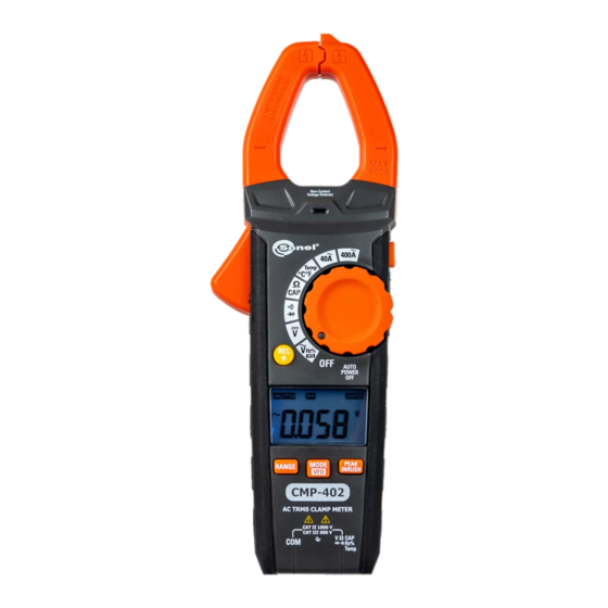
    4 Funktionsbeschreibung 4.1 Messklemmen und Funktionen CMP-402 ● CMP-403 – BEDIENUNGSANLEITUNG...
  • Seite 112 – Messung von Gleichspannung  Hz% VFD – Messung von Wechselspannung, Messung von Fre- quenz und Tastverhältnis, Messung von Strom und Spannung nach einem Wechselrichter, Frequenzumrichter, in einem VFD- System  OFF – das Messgerät ist ausgeschaltet CMP-402 ● CMP-403 – BEDIENUNGSANLEITUNG...
  • Seite 113  PEAK / INRUSH-Taste Zeigt den Spitzenwert des gemessenen Signals an (kurz drü- cken) Anzeige des Einschaltstroms (kurz drücken) COM-Messanschluss Messeingang, gemeinsam für alle Messfunktionen außer Strom. Messanschluss VΩCAP Hz%Temp Messeingang für andere Messungen als die Strommessung. CMP-402 ● CMP-403 – BEDIENUNGSANLEITUNG...
  • Seite 114: Anzeige

    / µ / m / k / M Das Präfix der Mehrfachmesseinheit Spannungsmessung Aktuelle Messung Messung der Kapazität Ω Messung des Widerstands Messung der Frequenz Messung der Einschaltdauer Negativer Auslesewert – Überschreitung des Messbereichs CMP-402 ● CMP-403 – BEDIENUNGSANLEITUNG...
  • Seite 115: Leitungen

    Verwendung von Original-Messleitungen. WARNUNG Der Anschluss falscher Leitungen kann zu Strom- schlägen oder Messfehlern führen.  Die Tastköpfe sind zusätzlich mit einem abnehmbaren Spitzenschutz ausgestattet.  Die Sonden müssen in einem dafür vorgesehenen Be- reich gelagert werden. CMP-402 ● CMP-403 – BEDIENUNGSANLEITUNG...
  • Seite 116: Messungen

    Wenn Gleichstrom gemessen wird und das Messgerät nicht an den zu prüfenden Stromkreis angeschlossen ist, es aber trotzdem einen Wert ungleich Null anzeigt, müssen Sie es durch Drücken und Hal- -Taste zurücksetzen. ten der REL CMP-402 ● CMP-403 – BEDIENUNGSANLEITUNG...
  • Seite 117: Berührungsloser Spannungsdetektor

     Die Art und Dicke der Isolierung, der Abstand zur Strom- quelle, abgeschirmte Kabel und andere Faktoren können den Betrieb des Prüfgeräts beeinflussen. Wenn Sie sich über das Prüfergebnis unsicher sind, prüfen Sie das Vor- handensein von Spannung auf andere Weise. CMP-402 ● CMP-403 – BEDIENUNGSANLEITUNG...
  • Seite 118: Spannungsmessung

     Schließen Sie die schwarze Messleitung an die Anschluss COM und die rote Messleitung an die Klemme VΩCAP Hz%Temp an,  Kontaktieren Sie die Spitzen der Prüfspitzen mit den Messpunkten,  Lesen Sie das Messergebnis auf dem Display ab. CMP-402 ● CMP-403 – BEDIENUNGSANLEITUNG...
  • Seite 119: Messung % Der Einschaltdauer (Impulsfüllungsanzeige)

    Seite des zu prüfenden Elements ab- zutrennen, um zu verhindern, dass der verbleibende Teil des Stromkreises das Ablesen des Widerstandswertes stört,  Lesen Sie das Messergebnis auf dem Display ab. CMP-402 ● CMP-403 – BEDIENUNGSANLEITUNG...
  • Seite 120: Durchgangsprüfung Des Stromkreises

     Schließen Sie die schwarze Messleitung an die Anschluss COM und die rote Messleitung an die Anschluss VΩCAP Hz%Temp an,  Kontaktieren Sie die Spitzen der Prüfspitzen mit der Diode. Die rote Prüfspitze sollte die Anode und die schwarze die Kathode berühren, CMP-402 ● CMP-403 – BEDIENUNGSANLEITUNG...
  • Seite 121: Messung Der Kapazität

     Schließen Sie die schwarze Messleitung an die Klemme COM und die rote Messleitung an die Anschluss VΩCAP Hz%Temp an,  Kontaktieren Sie die Tastspitzen mit dem zu prüfenden Konden- sator,  Lesen Sie das Messergebnis auf dem Display ab. CMP-402 ● CMP-403 – BEDIENUNGSANLEITUNG...
  • Seite 122: Temperaturmessung

    Lesen Sie das Messergebnis auf dem Display ab,  Trennen Sie nach Abschluss der Messungen die Sonde vom Messgerät. VORSICHT! Gefahr von Verbrennungen. Der Temperaturfühler erwärmt sich und passt sich der Temperatur des getesteten Objekts an. CMP-402 ● CMP-403 – BEDIENUNGSANLEITUNG...
  • Seite 123: Besondere Funktionen

     Diese Funktion ist für den Diodentest, Durchgang, Frequ- enz und Einschaltdauer nicht verfügbar. 6.1.2 Hintergrundbeleuchtung des Displays 2 Sekunden lang gedrückt halten, Wenn Sie die Taste REL wird die Hintergrundbeleuchtung des Displays ein- und ausgeschaltet. CMP-402 ● CMP-403 – BEDIENUNGSANLEITUNG...
  • Seite 124: Range-Taste

    VFD-System zu messen:  stellen Sie den Drehschalter auf die Position Spannungsmessung bzw. Strommessung,  halten Sie die MODE/VFD-Taste gedrückt, bis „VFD“ erscheint. Um den Modus zu deaktivieren, drücken und halten Sie die Taste MODE/VFD. CMP-402 ● CMP-403 – BEDIENUNGSANLEITUNG...
  • Seite 125: Peak / Inrush-Taste

     Während INRUSH aktiv ist, ist die automatische Messwertanpas- sung deaktiviert, daher ist es ratsam, die Funktion zu starten, nachdem die Messleitungen an die Messstelle angeschlossen wurden. Wenn Sie INRUSH vorher starten, kann es zu Messbe- reichsüberschreitungen kommen. CMP-402 ● CMP-403 – BEDIENUNGSANLEITUNG...
  • Seite 126: H -Taste

     Lassen Sie die MODE/VFD-Taste los. Wenn die automatische Ab- schaltung deaktiviert ist, zeigt das Display das Symbol APO nicht an. Jedes Durchlaufen des Drehschalters durch die Position "OFF" bei nicht gedrückter MODE/VFD-Taste, aktiviert die Auto-Off-Funktion erneut. CMP-402 ● CMP-403 – BEDIENUNGSANLEITUNG...
  • Seite 127: Auswechseln Der Batterie

    Um einen Stromschlag zu vermeiden, verwenden Sie das Messgerät nicht, wenn die Batteriefachabdeckung nicht vorhanden oder nicht richtig befestigt ist. Das CMP-402 / 403 wird mit drei LR03 AAA 1,5 V Batterien be- trieben. Es wird empfohlen, Alkalibatterien zu verwenden. So tauschen Sie die Batterie aus: ...
  • Seite 128: Wartung Und Pflege

    Messgerät, um ein Auslaufen und Schäden zu vermeiden. LÄNGER TAGE 12. WENN MESSGERÄT GELAGERT WERDEN MUSS, nehmen Sie die Batterien heraus und bewahren Sie sie separat auf. Das elektronische System des Zählers erfordert keine Wartung. CMP-402 ● CMP-403 – BEDIENUNGSANLEITUNG...
  • Seite 129: Lagerung

    Ausgediente elektronische Geräte sind gemäß dem Gesetz über Elektro- und Elektronik-Altgeräte an einer Sammelstelle abzu- geben. Bevor das Gerät an eine Sammelstelle geschickt wird, dürfen keine Elemente demontiert werden. Beachten Sie die örtlichen Vorschriften zur Entsorgung von Verpackungen, Altbatterien und -akkumulatoren. CMP-402 ● CMP-403 – BEDIENUNGSANLEITUNG...
  • Seite 130: Spezifikationen

    1000 V  Alle AC-Spannungsbereiche sind von 5% bis 100% des Be- reichs angegeben  Eingangsimpedanz: 10 MΩ  Frequenzbereich: 50 Hz...1000 Hz  Überlastschutz: 1000 V DC/AC RMS  AC-Spannungsbereich für VFD-Funktion: 100 V…600 V CMP-402 ● CMP-403 – BEDIENUNGSANLEITUNG...
  • Seite 131 0,001 µF  (3,0% v.Mw. + 5 Digits) 99,99 µF 0,01 µF 999,9 µF 0,1 µF 9,999 mF 0,001 mF  (5,0% v.Mw. + 5 Digits) 99,99 mF 0,01 mF  Überlastschutz: 300 V DC/AC RMS CMP-402 ● CMP-403 – BEDIENUNGSANLEITUNG...
  • Seite 132 Bereich Auflösung Genauigkeit -20,0…+1000C 0,1 oder 1C ± (3% v.Mw. + 3C) -4,0…+1832F 0,1 oder 1F ± (3% v.Mw. + 5F)  Die Genauigkeit des Temperaturfühlers wird nicht berücksichtigt  Überlastschutz: 300 V DC/AC RMS CMP-402 ● CMP-403 – BEDIENUNGSANLEITUNG...
  • Seite 133: Betriebsdaten

    .................... 4000 Zählungen mit Funktionsanzeigen Abmessungen ....................... 220 x 80 x 39 mm Metergewicht ▪ CMP-402 ..........................266 g ▪ CMP-402 (ohne Batterien) ..................... 230 g ▪ CMP-403 ..........................270 g ▪ CMP-403 (ohne Batterien) ..................... 234 g Betriebstemperatur......................+5..+40C Betriebsfeuchtigkeit ........< 80% bei ≤ 31C lineare Minderung auf 50% bei 40C Lagertemperatur ......................
  • Seite 134: Service

    12 Service Der Anbieter von Garantie- und Nachgarantieservices ist: SONEL S.A. Wokulskiego 11 58-100 Świdnica Polen Tel. +48 74 884 10 53 (Kundenbetreuung) E-Mail: customerservice@sonel.com Webseite: www.sonel.com VORSICHT! Servicereparaturen dürfen nur vom Hersteller durchgeführt werden. CMP-402 ● CMP-403 – BEDIENUNGSANLEITUNG...
  • Seite 136 CMP-402 ● CMP-403 – BEDIENUNGSANLEITUNG...

Diese Anleitung auch für:

Cmp-403Wmgbcmp402Wmgbcmp403

Inhaltsverzeichnis