krick WSP 47 Baubeschreibung
Vorschau ausblenden
Andere Handbücher für WSP 47:
- Baubeschreibung (26 Seiten) ,
- Baubeschreibung (26 Seiten)
Verfügbare Sprachen
Verfügbare Sprachen
Quicklinks
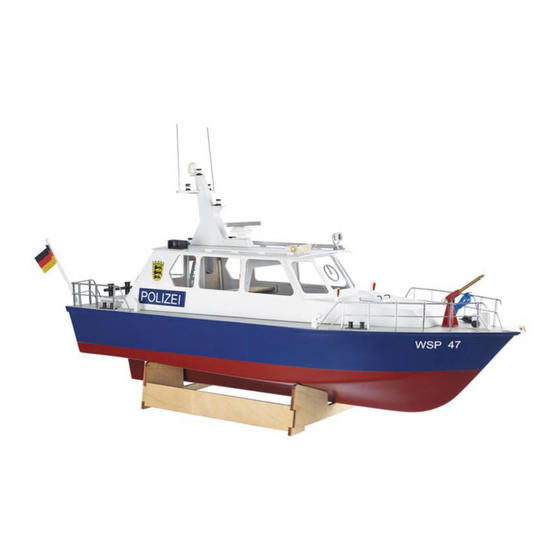
Baubeschreibung Polizeiboot WSP 47
Wir beglückwünschen Sie zum Erwerb des
Polizeibootes „WSP 47". Dieses Modell ist im
Wesentlichen für den Einsteiger in das Hobby
des aktiven Schiffmodellbaus gedacht, macht
aber auch dem erfahrenen Schiffsmodellbauer
viel Freude beim Bau und Fahrbetrieb.
Zum Bau des Modells benötigen Sie noch
folgende Klebstoffe, Spachtelmassen und Far-
ben:
- Sekundenkleber 20g dünn (Best.-Nr. 44050)
- Sekundenkleber 20g mittel (Best.-Nr. 44051)
- Zweikomponentenkleber 5min-Epoxy 100g
(Best.-Nr. 80479)
- Holzleim UHU Holz wasserfest 75g
(Best.-Nr. 48515)
- Zweikomponentenkleber Stabilit Express 30g
Best.-Nr. ro5015
- Super-Leichtspachtel Micro-Fill weiß 295 ml
(Best.-Nr. 80480)
- Porenfüller (Lord Nelson Porenfüller
Best.-Nr. 80110)
- Klarlack (Niedergang, Türen),
Bestell-Nr. 80112
Stand 26. März 2019
Bestell-Nr. 20360
- Farbspraydose blau
rot
hellgrau
weiß
Grundierung
- Acrylfarben zum streichen in rot, grün, silber
und schwarz für die Beschlagteile
Folgendes Werkzeug stellt die Grundausstat-
tung zum Bau des "WSP 47" dar:
- Bastelmesser (Best.-Nr. 416002)
- Handbohrmaschine (Best.-Nr. 473841)
- Sandpapierfeilen (Best.-Nr. 491016)
- Schleifklotz (Best.-Nr. 490080)
- Schleifpapier Körnung 180, 320, 400 und
600 (Set Best.-Nr. 490190)
- Rundfeile ca. Ø 6 mm
- Bohrer Ø 1 mm, 1,5 mm, 2 mm, 3 mm, 4
mm, 6,5 mm
- Seitenschneider (Best.-Nr. 455550)
Zum Abkleben beim Lackieren wird noch PVC-
Klebeband oder Papierklebeband benötigt.
Kein Kreppband!
Seite 1
Bestell-Nr. 320053
Bestell-Nr. 320020
Bestell-Nr. 316410
Bestell-Nr. 320010
Bestell-Nr. 316410
©
Krick Modelltechnik Knittlingen

Verwandte Anleitungen für krick WSP 47


Inhaltszusammenfassung für krick WSP 47
- Seite 1 Baubeschreibung Polizeiboot WSP 47 Bestell-Nr. 20360 Wir beglückwünschen Sie zum Erwerb des - Farbspraydose blau Bestell-Nr. 320053 Polizeibootes „WSP 47“. Dieses Modell ist im Bestell-Nr. 320020 Wesentlichen für den Einsteiger in das Hobby hellgrau Bestell-Nr. 316410 des aktiven Schiffmodellbaus gedacht, macht weiß...
- Seite 2 Position des Stevenrohres an- stellung leisten und gibt Ihnen die Gewähr, zeichnen. dass Ihr eigenes “WSP 47” ein funktionieren- des und schönes Modell wird. Sollten Sie kei- nen erfahrenen Modellbauer in Ihrem Bekann- tenkreis und/oder Freundeskreis haben, so wenden Sie sich an einen Schiffsmodellbau- club in Ihrer Nähe, bzw.
- Seite 3 Jetzt den Süllrand (10 bis 13) so gegen die Leisten kleben, dass die Sperrholzstreifen unten bündig sind und über das Deck überste- hen. So wird verhindert, dass Spritzwasser in den Rumpf fließen kann. Seite 3 © Stand 26. März 2019 Krick Modelltechnik Knittlingen...
- Seite 4 Dann werden die Innenteile auf eine Außensei- te (160) des Ruders so geklebt, dass der Ab- stand für die Ruderachse entsteht. Rauen Sie die Ruderachse im unteren Bereich gut auf. Seite 4 © Stand 26. März 2019 Krick Modelltechnik Knittlingen...
- Seite 5 Anschlie- ßend diese Teile wasserfest lackieren. Auch das fertige Deck sollte auf der Unterseite ent- sprechend wasserfest lackiert werden. Als nächstes die Anschlusskabel (24) anlöten. Seite 5 © Stand 26. März 2019 Krick Modelltechnik Knittlingen...
- Seite 6 Abdichtung entsteht. Nachdem der Kleber getrocknet ist, schleifen Sie die überstehenden Ränder des Bootsrump- fes bis auf das Deck herunter. Anschließend verspachteln Sie die eventuell noch vorhanden Spalten mit Leichtspachtel. Seite 6 © Stand 26. März 2019 Krick Modelltechnik Knittlingen...
- Seite 7 Wenn die Klebestellen getrocknet sind wird die Dachverstrebung 40 eingeklebt. 2. Kabinendach vorne Als nächstes vorderes Dach (35) mit den Aus- sparungen zwischen die Seitenteile setzen und im Bereich der Aussparung verkleben. Seite 7 © Stand 26. März 2019 Krick Modelltechnik Knittlingen...
- Seite 8 Am Mittelteil als erstes die Unterkante ca. 45 von innen kleben und mit Klammern sichern. Grad anschrägen. Passen Sie das Abschlussteil (37) vorne am Aufbau ein und verkleben es. Die Oberkante Seite 8 © Stand 26. März 2019 Krick Modelltechnik Knittlingen...
- Seite 9 Im nächsten Schritt wird die Plicht angefertigt. Mit dem Aufkleben des Daches (36) beginnt Sie benötigen dazu die Teile 49, 50 und 51. der letzte Schritt beim Bau des Aufbaus. Seite 9 © Stand 26. März 2019 Krick Modelltechnik Knittlingen...
- Seite 10 Mit einem Geodreieck die Winkligkeit prüfen. Sollten Sie die Schiffslampen am Mast be- leuchten wollen, empfiehlt es sich jetzt den Kabelschacht so vor zu bereiten, dass die Kabel später im Inneren durchgeführt werden Seite 10 © Stand 26. März 2019 Krick Modelltechnik Knittlingen...
- Seite 11 Messingröhrchen 2 x 1,5 x 7 mm (104) auf Jetzt die Rah mit Sekundenkleber im Mast und den Antennenfuß in der Rah einkleben. Wenn der Klebstoff getrocknet ist, die Rah leicht nach hinten biegen. Seite 11 © Stand 26. März 2019 Krick Modelltechnik Knittlingen...
- Seite 12 Aus den Teilen 63 bis 75 fertigen wir jetzt das Radar und soweit gewünscht auch den Antrieb für das Radar. Als nächstes schleifen wir die Rückseite des Radarbalkens 68 rund. Seite 12 © Stand 26. März 2019 Krick Modelltechnik Knittlingen...
- Seite 13 Aufbau eingeschoben. Den Motor am Motorträger festschrauben. Den Kupplungsschlauch 71 auf die Motorwelle auf- schieben. Den Motorträger mit Motor wieder ausbauen. Die Auflagen 74 im Anschluss komplett verkle- ben. Seite 13 © Stand 26. März 2019 Krick Modelltechnik Knittlingen...
- Seite 14 Jetzt sollten die Holzteile mit Porenfüller la- gang zusammen. ckiert und geschliffen werden. Anschließend den Windenkörper weiß oder hellgrau lackie- ren. Danach den Antriebsmotor (80) und das Spill (81) ankleben. Seite 14 © Stand 26. März 2019 Krick Modelltechnik Knittlingen...
- Seite 15 Im nächsten Schritt das Standrohr 130 in den Sockel einkleben. Aus den Teilen 111, 112 und 113 die beiden Lampenborde herstellen. 9. Rettungsringhalter Als nächstes werden die Messingteile 128 und 129 zusammengesetzt. Seite 15 © Stand 26. März 2019 Krick Modelltechnik Knittlingen...
- Seite 16 Kopföffnung stecken und den Silikonschlauch Aus den Teilen 148, 153, 154 und 155 wird aufschieben. das Blaulicht zusammen gesetzt. Als letztes die Achse 131 in das Handrad ein- kleben und am Löschmonitor anbringen. Seite 16 © Stand 26. März 2019 Krick Modelltechnik Knittlingen...
- Seite 17 Die Teile 134, 135, 136 und 137 werden zum Schlepppoller zusammen gefügt. Bohren Sie nun die beiden 4mm Löcher in die Stützen 135. Nun alle Teile zu Schlepppoller zusammen kleben. Seite 17 © Stand 26. März 2019 Krick Modelltechnik Knittlingen...
- Seite 18 14. GPS-Antenne Aus den Teilen 149.1 bis 149.5 wird die GPS – Antenne gefertigt. 149.5 Die Teile entsprechend Ihrer Größe zusammen kleben. Die verklebten Teile zu einer Halbkugel rund- schleifen. Seite 18 © Stand 26. März 2019 Krick Modelltechnik Knittlingen...
- Seite 19 Als erstes bohren Sie ein Loch mit 4 mm einen freien Kanal Ihres Empfängers ange- Durchmesser hinter der Schiffsschraube zum schlossen wird. Einkleben des Ansaugröhrchens 159 und kle- ben dieses mit Uhu Acrylit in den Rumpf ein. Seite 19 © Stand 26. März 2019 Krick Modelltechnik Knittlingen...
- Seite 20 Klebeband am wir wünschen Ihnen dabei viel Freude und Motorträger befestigt werden. Der Drehzahl- Erfolg mit Ihrem Polizeiboot „WSP 47“. steller muss so befestigt sein, dass die Ein- stell- und Trimmpotentiometer (wenn vorhan- Bei Rückfragen und Hilfestellung zum Bau und...
- Seite 21 Stückliste Polizeiboot WSP 47 Achtung die Positionsnummern sind nicht fortlaufend. Position Bezeichnung Material Abmessung Anzahl Rumpf Tiefziehteil Ständerteil vorne Sperrholz Laserbrett (1) 5 mm Ständerteil hinten Sperrholz Laserbrett (1) 5 mm Ständer-Verbinder Sperrholz Laserbrett (1) 5 mm Deck Sperrholz Laserbrett (2) 3 mm Verstärkungsleiste Seite...
- Seite 22 Laserbrett (5) 1,5 mm Düse Messing Fertigteil Strahlrohr Messingrohr 4 x 3 x 45 mm Standrohr Messingrohr 7 x 6 x 32 mm Achse Messingdraht 1,5 x 10 mm Handrad Fertigteil Plastik Seite 22 © Stand 26. März 2019 Krick Modelltechnik Knittlingen...
- Seite 23 Laserbrett (6) 1,5 mm Ruderblatt innen vorne Sperrholz Laserbrett (6) 1,5 mm Ruderblatt innen hinten Sperrholz Laserbrett (6) 1,5 mm Ruderachse Messing 3 x 85 mm Wappen Etikett Schriftzüge Etikett Seite 23 © Stand 26. März 2019 Krick Modelltechnik Knittlingen...
- Seite 24 Teilenummern der Laserschnitt-Teile 149.2 Laserbrett 3 Laserbrett 2 Seite 24 © Stand 26. März 2019 Krick Modelltechnik Knittlingen...
- Seite 25 149.4 149.3 149.1 149.5 Laserbrett 1 Laserbrett 4 Laserbrett 5 (kann aus fertigungstechnischen Gründen geteilt sein) Seite 25 © Stand 26. März 2019 Krick Modelltechnik Knittlingen...
- Seite 26 Vorlage zum Ausschneiden des Fenstermaterials Seite 26 © Stand 26. März 2019 Krick Modelltechnik Knittlingen...
- Seite 50 Part numbers of Laser Parts 149.2 Laser sheet 3 Laser sheet 2 Seite 24 © Stand Juli 2014 Krick Modelltechnik Knittlingen...
- Seite 51 149.4 149.3 149.5 149.1 Laser sheet 1 Laser sheet 4 Laser sheet 5 Seite 25 © Stand Juli 2014 Krick Modelltechnik Knittlingen...
- Seite 52 Pattern for Cutting of Window Material Seite 26 © Stand Juli 2014 Krick Modelltechnik Knittlingen...
- Seite 77 Référence des pièces découpées laser 149.2 Seite 25 © Stand Mai 2014 Krick Modelltechnik Knittlingen...
- Seite 78 149.4 149.3 149.5 149.1 Seite 26 © Stand Mai 2014 Krick Modelltechnik Knittlingen...
- Seite 79 Patron pour la découpe des vitrages Seite 27 © Stand Mai 2014 Krick Modelltechnik Knittlingen...