
Optimum OptiTurn TU2807VB Handbücher
Anleitungen und Benutzerhandbücher für Optimum OptiTurn TU2807VB. Wir haben 2 Optimum OptiTurn TU2807VB Anleitungen zum kostenlosen PDF-Download zur Verfügung: Betriebsanleitung
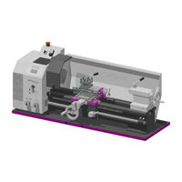
Optimum OptiTurn TU2807VB Betriebsanleitung (190 Seiten)
Marke: Optimum
|
Kategorie: Drehmaschinen
| Dateigröße: 7 MB
Inhaltsverzeichnis
-
Elektrik17
-
Spindelstock18
-
Schlitten18
-
Emissionen19
-
Reitstock19
-
Arbeitsraum19
-
Anlieferung22
-
Schmierung26
-
Bedienung31
-
Sicherheit32
-
Wahlschalter36
-
Kegeldrehen42
-
Gewindearten50
-
Reitstock59
-
Langdrehen60
-
Sicherheit72
-
Vorbereitung72
-
Reinigung73
-
Störungen78
-
Anhang79
-
Lagerung81
-
Abbauen82
-
Demontieren82
-
Safety86
-
Rating Plate86
-
Safety Instructions (Warning Notes)87
-
Classification of Hazards87
-
Pictograms87
-
Intended Use88
-
Reasonably Foreseeable Misuses89
-
Avoidance of Misapplication89
-
Potential Dangers that Can be Caused by the Lathe89
-
Qualification90
-
Target Group Private Users90
-
Obligations of the User90
-
Additional Requirements Regarding the Qualification90
-
Operator Positions90
-
Safety Measures During Operation91
-
Safety Devices91
-
Emergency-Stop Button92
-
Protective Cover of the Headstock92
-
Lathe Chuck Protection with Position Switch93
-
Protective Cover Lead Screw and Feed Rod93
-
Safety Check93
-
Personal Protective Equipment94
-
Safety During Operation94
-
Disconnecting and Securing the Lathe95
-
Using Lifting Equipment95
-
Mechanical Maintenance Work95
-
Electronics95
-
Technical Specification96
-
Electrical Connection96
-
Drive Motor Power96
-
Work Areas96
-
Headstock96
-
Feeds and Pitches96
-
Slides96
-
Emissions97
-
Tailstock97
-
Machine Dimensions97
-
Work Area97
-
Environmental Conditions97
-
Operating Material97
-
Delivery, Interdepartmental Transport, Assembly and Commissioning99
-
Notes on Transport, Installation, Commissioning99
-
General Risks During Internal Transport99
-
Delivery100
-
Standard Scope of Delivery100
-
Load Suspension Point100
-
Dimensions of the Machine101
-
Centre of Gravity of the Machine Without Machine Base101
-
With an Optional Machine Base102
-
Lifting with Lifting Equipment103
-
Lifting with a Forklift103
-
Installation Conditions103
-
Cleaning the Machine103
-
Lubrication104
-
First Commissioning104
-
Electrical Connection104
-
Warming up the Machine104
-
Available Accessories105
-
Lathe Chuck Assembly Instruction106
-
Chuck Flange 3441312 - Ø 125 , Short Taper106
-
Chuck Flange Ø 160 , Short Taper107
-
Collet Chuck Assembly Instruction108
-
Operation109
-
Control and Indicating Elements109
-
Safety110
-
Overview of the Control Elements110
-
Overview of Indicator Elements111
-
Control Elements111
-
Switching on the Machine112
-
Switching the Machine off112
-
Resetting an Emergency Stop Condition112
-
Power Failure, Restoring Readiness for Operation112
-
Speed Setting112
-
Changing the Speed or the Speed Range113
-
Fixing the Lathe Saddle113
-
Automatic Feed Engaging Lever114
-
Changing the Feed Rate114
-
Selector Switch114
-
Changing the Change Gears114
-
Tables for Thread Cutting115
-
Arrangement of the Change Gears116
-
Tool Holder116
-
Lathe Spindle Fixture116
-
Replacing the Clamping Jaws on the Lathe Chuck117
-
Clamping a Workpiece into the Three Jaw Chuck118
-
Taper Turning119
-
Taper Turning with the Top Slide119
-
Taper Turning with the Tailstock119
-
Turning of Cones with High Precision119
-
Standard Values for Cutting Data When Turning122
-
Cutting Speed Table122
-
Terms for the Rotating Tool123
-
Cutting Edge Geometry for Turning Tools124
-
Types of Cutting Form Levels125
-
Tapping of External and Internal Threads126
-
Thread Types127
-
Metric Threads (60° Flank Angle)129
-
British Thread (55° Flank Angle)130
-
Indexable Inserts132
-
Examples for Thread Cutting133
-
General Operating Instructions134
-
Clamping Long Workpieces134
-
Mounting of Rests135
-
Mounting of Follow Rest135
-
Mounting of Steady Rest135
-
Tailstock136
-
Cross-Adjustment of the Tailstock136
-
General Operating Instructions137
-
Longitudinal Turning137
-
Face Turning and Recessing137
-
Turning Short Tapers with the Top Slide137
-
Thread Cutting138
-
Cooling Lubricant138
-
Lathe Chuck - K11- 80 - 100 - 125 MM, Cylindrical Centring Mount140
-
Safety Instructions141
-
Basic Safety Instructions142
-
Optional Soft Lathe Chuck Jaws142
-
Calculating the Required Clamping Force for a Given Speed142
-
Clamping Force-Speed Diagram - Lathe Chuck K11-80143
-
Clamping Force-Speed Diagram - Lathe Chuck K11-100144
-
Clamping Force-Speed Diagram - Lathe Chuck K11-125144
-
Clamping Jaw Centrifugal Force145
-
Notes on Instruction of Operating Personnel147
-
Lubricating and Cleaning the Lathe Chuck147
-
Maintenance148
-
Safety148
-
Preparation148
-
Restarting148
-
Cleaning148
-
Check Up, Inspection and Maintenance149
-
Lubricating and Cleaning the Lathe Chuck153
-
Repair153
-
Customer Service Technician153
-
Malfunctions154
-
Appendix155
-
Copyright155
-
Terminology/Glossary155
-
Liability Claims/Warranty156
-
Storage157
-
Dismantling, Disassembling, Packing and Loading157
-
Decommissioning158
-
Dismantling158
-
Disassembly158
-
Packing and Loading158
-
Disposal of New Device Packaging158
-
Disposal of Lubricants and Cooling Lubricants158
-
Disposal Via Municipal Collection Facilities159
-
Product Follow-Up159
-
Ec Declaration of Conformity160
-
Ersatzteile - Spare Parts161
-
Ersatzteilbestellung - Ordering Spare Parts161
-
Hotline Ersatzteile - Spare Parts Hotline161
-
Service Hotline161
-
Ersatzteilzeichnungen - Spare Part Drawings162
-
Oberschlitten - Top Slide162
-
Planschlitten- Cross Slide164
-
Reitstock - Tailstock168
-
Maschinenbett - Machine Bed170
-
Vorschubgetriebe - Feed Gear172
-
Maschinenschilder - Machine Labels178
-
Schaltplan - Wiring Diagram181
-
Packliste | Packing List182
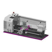
Optimum OptiTurn TU2807VB Betriebsanleitung (110 Seiten)
Drehmaschine
Marke: Optimum
|
Kategorie: Drehmaschinen
| Dateigröße: 5 MB
Inhaltsverzeichnis
-
Elektrik15
-
Spindelstock16
-
Schlitten16
-
Emissionen17
-
Reitstock17
-
Arbeitsraum17
-
Anlieferung20
-
Schmierung24
-
Bedienung30
-
Sicherheit31
-
Wahlschalter35
-
Kegeldrehen41
-
Gewindearten49
-
Reitstock58
-
Langdrehen59
-
Sicherheit71
-
Vorbereitung71
-
Reinigung72
-
Störungen100
-
Anhang101
-
Lagerung103
-
Abbauen104
-
Demontieren104