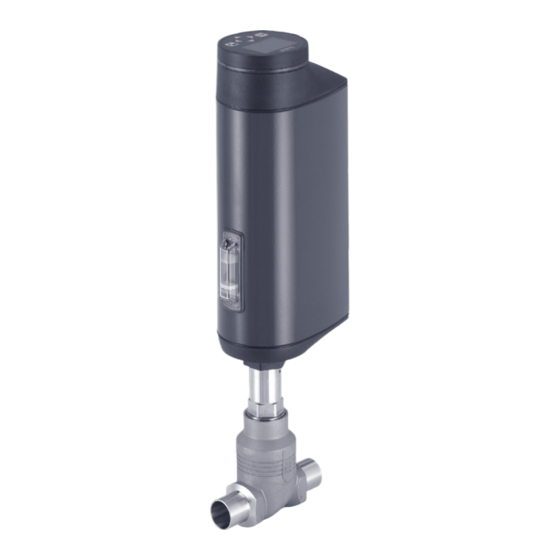
bürkert 3360 Schnellstartanleitung
Elektromotorisches regelventil
Vorschau ausblenden
Andere Handbücher für 3360:
- Bedienungsanleitung (165 Seiten) ,
- Schnellstart (158 Seiten) ,
- Schnellstartanleitung (53 Seiten)

Verwandte Anleitungen für bürkert 3360


Inhaltszusammenfassung für bürkert 3360
- Seite 59 Typ 3360, 3361 Inhaltsverzeichnis 8 ELEKTRISCHE INSTALLATION ............80 1 DER QUICKSTART ..................60 1.1 Begriffsdefinition ..............60 8.1 Elektrische Installation mit Rundsteckverbinder ....80 8.2 Elektrischer Anschluss Feldbus-Gateway ......85 1.2 Darstellungsmittel ..............61 8.3 Elektrische Installation mit Kabelverschraubung 2 BESTIMMUNGSGEMÄSSE VERWENDUNG........ 62 (nur AG2) ..................86 3 GRUNDLEGENDE SICHERHEITSHINWEISE ......62 9 INBETRIEBNAHME .
-
Seite 60: Der Quickstart
Typ 3360, 3361 DerQuickstart 12 MANUELLE BETÄTIGUNG DES VENTILS ........107 DER QUICKSTART 12.1 Ventil elektrisch betätigen ..........107 Der Quickstart enthält in Kurzform die wichtigsten Informationen und 12.2 Ventil mechanisch betätigen ..........109 Hinweise für den Gebrauch des Geräts. Die ausführliche Beschreibung finden Sie in der Bedienungsanleitung für den Typ 3360, 3361. 13 INDUSTRIAL ETHERNET ..............111 Bewahren Sie den Quickstart für jeden Benutzer gut zugänglich auf. 13.1 Feldbus-Gateway ..............111 Der Quickstart muss jedem neuen Eigentümer des Geräts wieder zur 13.2 Zugang zur büS-Serviceschnittstelle....... 112 Verfügung stehen. 14 CANopen ..................... 112 Wichtige Informationen zur Sicherheit! 15 büS . -
Seite 61: Darstellungsmittel
Typ 3360, 3361 DerQuickstart • AG2: Antriebsgröße 2 mit einer Nennkraft von 1300 oder 2500 N Verweist auf Informationen in dieser Bedienungsanleitung für Sitzgröße 3...50 oder in anderen Dokumentationen. AG3: Antriebsgröße 3 mit einer Nennkraft von 7700 oder 10000 N ▶ Markiert eine Anweisung zur Vermeidung einer Gefahr. für Sitzgröße 25...100 → Markiert einen auszuführenden Arbeitsschritt. • In dieser Anleitung steht die Einheit bar für den Relativdruck. Der Absolutdruck wird gesondert in bar(abs) angegeben. Markiert ein Resultat. Darstellungsmittel MENUE Darstellung für Software-Oberflächentexte. GEFAHR! Warnt vor einer unmittelbaren Gefahr. ▶ Bei Nichtbeachtung sind Tod oder schwere Verletzungen die Folge. WARNUNG! Warnt vor einer möglichen, gefährlichen Situation. ▶ Bei Nichtbeachtung drohen schwere Verletzungen oder Tod. VORSICHT! Warnt vor einer möglichen Gefährdung. ▶ Bei Nichtbeachtung drohen mittelschwere oder leichte Verletzungen. ACHTUNG! Warnt vor Sachschäden. Bezeichnet wichtige Zusatzinformationen, Tipps und Empfehlungen. -
Seite 62: Bestimmungsgemässe Verwendung
Typ 3360, 3361 BestimmungsgemäßeVerwendung BESTIMMUNGSGEMÄSSE GRUNDLEGENDE VERWENDUNG SICHERHEITSHINWEISE Bei nicht bestimmungsgemäßem Einsatz des elektromotori- Diese Sicherheitshinweise berücksichtigen keine bei Montage, Betrieb schen Regelventils vom Typ 3360, 3361 können Gefahren für und Wartung auftretenden Zufälle und Ereignisse. Der Betreiber ist Personen, Anlagen in der Umgebung und die Umwelt entstehen. dafür verantwortlich, dass die ortsbezogenen Sicherheitsbestim- mungen, auch in Bezug auf das Personal, eingehalten werden. Das elektromotorische Regelventil ist für die Steuerung des Durchflusses von flüssigen und gasförmigen Medien konzipiert. ▶ Standardgeräte dürfen nicht im explosionsgefährdeten Bereich eingesetzt werden. Sie besitzen nicht das separate Ex- Verletzungsgefahr durch hohen Druck. Typschild, das die Zulassung für den explosionsgeschützten ▶ Vor Arbeiten an Anlage oder Gerät, den Druck abschalten und Bereich kennzeichnet. Leitungen entlüften oder entleeren. ▶ Zur Reinigung der Oberfläche des Geräts sind keine alkalischen Verbrennungsgefahr und Brandgefahr. Reinigungsmittel zugelassen. Bei längerer Einschaltdauer oder durch heißes Medium kann die ▶ Ist die Ventilstellung bei Stromausfall sicherheitstechnisch Geräteoberfläche heiß werden. relevant: Nur Geräte einsetzen, die den SAFEPOS energy-pack ▶... - Seite 63 Typ 3360, 3361 BestimmungsgemäßeVerwendung ▶ Ist die Ventilstellung bei Stromausfall sicherheitstechnisch ▶ Am Gerät keine inneren oder äußeren Veränderungen vorneh- relevant: Nur Geräte einsetzen, die den SAFEPOS energy-pack men und nicht mechanisch belasten. (optionalen Energiespeicher) besitzen. ▶ Schweres Gerät ggf. nur mit Hilfe einer zweiten Person und mit ▶ Im Menü SAFEPOS eine für den Prozess sichere Ventilstellung geeigneten Hilfsmitteln transportieren, montieren und demontieren. wählen. ▶ Vor unbeabsichtigter Betätigung sichern. Gefahr durch laute Geräusche. ▶ Nur geschultes Fachpersonal darf Installations- und Instandhal- ▶ Abhängig von den Einsatzbedingungen können durch das Gerät tungsarbeiten ausführen.
-
Seite 64: Allgemeine Hinweise
Typ 3360, 3361 AllgemeineHinweise ALLGEMEINE HINWEISE AUFBAU UND FUNKTION Das elektromotorische Regelventil besteht aus einem elektromotorisch Kontaktadresse angetriebenen Linearantrieb, einem Regelkegel und einem 2-Wege- Deutschland Geradsitz-Ventilgehäuse oder einem 2-Wege-Schrägsitz-Ventilgehäuse. Bürkert Fluid Control Systems • Die Anströmung ist immer unter Sitz. Sales Center Ventilsitze: Christian-Bürkert-Str. 13-17 • Beim Geradsitz-Regelventil ist der Ventilsitz eingeschraubt. D-74653 Ingelfingen Durch den Tausch des eingeschraubten Ventilsitzes kann die Sitz- Tel. + 49 (0) 7940 - 10-91 111 größe auf einfache Weise reduziert werden. Fax + 49 (0) 7940 - 10-91 448 E-mail: info@burkert.com • Beim Schrägsitz-Regelventil ist der Ventilsitz ins Ventilgehäuse ein- gearbeitet. Eine Reduzierung der Sitzgröße ist deshalb nicht möglich. Der Ventilsitz wird immer gegen den Mediumsstrom geschlossen,... -
Seite 65: Aufbau Des Elektromotorischen Regelventils
Typ 3360, 3361 AufbauundFunktion Aufbau des elektromotorischen Druckausgleichs- Regelventils element / Zugang zur mechanischen Handbetätigung Elektrische Anschlüsse Blinddeckel oder Display Blinddeckel oder Display mit SAFEPOS energy- (Rundsteck- mit Statusanzeige und Statusanzeige und pack (optional) verbinder oder Bajonettverschluss Bajonettverschluss Kabelverschraubung) Nur bei Geräten mit Prozessreglerfunktion Antriebsdeckel Antriebsdeckel Antriebsgehäuse Nur bei Geräten mit Antriebsgehäuse Elektrische Prozessreglerfunktion Anschlüsse Klarsichtfenster mit (Rundsteckverbinder) Druckausgleichselement Klarsichtfenster mit Stellungsanzeige nicht abschrauben! -
Seite 66: Anzeige Des Gerätezustands
Typ 3360, 3361 TechnischeDaten Anzeige des Gerätezustands TECHNISCHE DATEN Zur Anzeige von Gerätestatus und Ventilstellung können verschiedene Folgende produktspezifischen Angaben sind auf dem LED-Modi eingestellt werden (Beschreibung siehe Hauptanleitung). Typschild angegeben: Werkseitig eingestellter LED-Modus: „Ventilmodus + Warnungen“. • Spannung [V] (Toleranz ±10 %) und Stromart 5.2.1 Anzeigen im Ventilmodus + • Dichtwerkstoff Warnungen • Feldbusstandard Bei Gerätestatus „Normal“: Dauerhaftes Leuchten in der Farbe der • Durchflusskapazität Ventilstellung. Bei Gerätestatus die von „Normal“ abweichen: Blinken im Wechsel • Antriebsgröße der Farben für Ventilstellung und Gerätestatus. • Maximal zulässiger Betriebsdruck • Durchflussrichtung Ventil- Farbe für Farbe für Gerätestatus... -
Seite 67: Typschild
Typ 3360, 3361 TechnischeDaten Typschild 6.4.1 Zusatztypschild für UL-Zulassung (Beispiel) Zulässiger Temperaturbereich (Medium) Type AE33-SA Maximal zulässiger Betriebsdruck, Durchflussrichtung Power Supply Dichtwerkstoff, Durchflusskapazität, SELV / PELV only! LISTED Durchflusskennlinie Spannung, Gleichstrom, Maximale Stromstärke, Process Control Equipment Antriebsgröße (Nennkraft) E238179 Typ, Funktion (Stellungsregler / Prozessregler), Feldbusstandard Abb. 5: Zusatztypschild für UL-Zulassung 3360 Positioner büS U=24V Imax=3A AG2 (1300N) -
Seite 68: Zulässige Temperaturbereiche
Typ 3360, 3361 TechnischeDaten 6.5.1 Zulässige Temperaturbereiche WARNUNG! Minimaltemperaturen Verminderte Dichtschließfunktion bei zu hohem Umgebung: –25 °C Betriebsdruck. Medium: –10 °C (–40 °C auf Anfrage) Da der Ventilsitz gegen den Mediumsstrom geschlossen wird, Maximaltemperaturen kann ein zu hoher Betriebsdruck bewirken, dass der Ventilsitz Umgebung: i st von der Mediumstemperatur abhängig, siehe nach- nicht dicht schließt. folgendes Temperaturdiagramm. ▶ Der Betriebsdruck darf nicht höher sein als der auf dem Medium: i st von der Umgebungstemperatur abhängig, siehe Typschild angegebene Maximalwert. nachfolgendes Temperaturdiagramm Maximal zulässiger Betriebsdruck: siehe Typschild Bei Geräten mit Ventilsitzdichtung PTFE max. +130 °C . Medien: n eutrale Gase und Dampf. B ei Geräten mit Ventilsitzdichtung Edelstahl oder Flüssige Medien: Wasser, Alkohol, Öl, Treib-... - Seite 69 Typ 3360, 3361 TechnischeDaten 220 230 220 230 Mediumstemperatur [°C] Mediumstemperatur [°C] Abb. 6: Temperaturdiagramm AG2 Abb. 7: Temperaturdiagramm AG3 Beschreibung Beschreibung Geräte ohne Modul Geräte ohne Modul Geräte mit Display-Modul Geräte mit SAFEPOS energy-pack* Geräte mit Display-Modul mit/ohne SAFEPOS Geräte mit SAFEPOS energy-pack* energy-pack* oder mit Feldbus-Gateway mit/ohne Display-Modul Geräte mit Feldbus-Gateway mit/ohne Display-Modul mit/ * Die Lebensdauer des SAFEPOS energy-packs ist von der Mediums- ohne SAFEPOS energy-pack* temperatur und der Umgebungstemperatur abhängig (siehe Kapitel Elekt- rische Daten). * Die Lebensdauer des SAFEPOS energy-packs ist von der Mediums- temperatur und der Umgebungstemperatur abhängig (siehe Kapitel Elekt- Tab. 2: Beschreibung Temperaturdiagramm AG2 rische Daten).
- Seite 70 Typ 3360, 3361 TechnischeDaten Derating Druck- und Temperaturbereich Temperatur Betriebsdruck Einsatzgrenzen der Armatur (Derating Betriebsdruck) -10...+50 °C 14 bar Temperatur Betriebsdruck 100 °C 14 bar -10...+50 °C 25 bar 150 °C 13,4 bar 100 °C 24,5 bar 200 °C 12,4 bar 150 °C 22,4 bar 230 °C 11,7 bar 200 °C 20,3 bar Tab. 6: Derating des Betriebsdrucks nach JIS B 2220 10K 230 °C 19 bar Tab.
-
Seite 71: Allgemeine Technische Daten
Typ 3360, 3361 TechnischeDaten Allgemeine Technische Daten Elektrischer durch Anschlussklemmen (nur AG2) oder Anschluss: Rundstecker Werkstoffe Einbaulage: beliebig, Antrieb vorzugsweise nach oben Antriebsboden: PPS (AG2) / 1.4308 (AG3) Schalldruckpegel: <70 dB(A), kann abhängig von den Einsatz- Antriebsgehäuse: Aluminium EN AW 6063 pulverbeschichtet bedingungen höher sein. Sichtfenster: Kv-Wert: siehe Typschild oder Bedienungsanleitung Antriebsdeckel: PPS (AG2) / PC (AG3) 6.6.1 Elektrische Daten Ventilgehäuse: 316L GEFAHR! Gehäuseverbindung: AG2: 316L / 1.4401 AG3: 1.4401/ 1.4404/ 1.4435 / CF3M Elektrischer Schlag. Spindel: 1.4401 /1.4404 Die Schutzklasse III wird nur gewährleistet bei Verwendung eines Spindelführung: 1.4401 / 1.4404/316L mit kohlegefülltem... - Seite 72 Typ 3360, 3361 TechnischeDaten Energiespeicher SAFEPOS energy-pack Betriebsspannung: 2 4 V ±10 % max. Restwelligkeit 10 % A ufladezeit: maximal 100 Sekunden (abhängig von den Einsatzbedingungen) Betriebsstrom [A]*: L ebensdauer: bis zu 15 Jahre (abhängig von den Einsatzbedin- Typisch (ohne Ladestrom Maximal (zur Auslegung des gungen). Die Lebensdauer von 5 Jahren wurde unter folgenden SAFEPOS energy-pack) Netzteils) Bedingungen ermittelt: Umgebungstemperatur 30 °C (AG2) / 65 °C (AG3) Mediumstemperatur 165 °C 3,5 A Einschaltdauer 100 % Betriebsdruck 5 bar Der Betriebsstrom kann bei Bedarf reduziert werden: Nennweite DN32 (AG2) / DN65 (AG3) 1. Stellgeschwindigkeit X.TIME reduzieren. 2. Geräte mit SAFEPOS energy-pack: Funktion „Control if Analoge Eingänge: ( galvanisch von Versorgungsspannung und ready“ einstellen. Siehe auch Bedienungsanleitung. analogem Ausgang getrennt) Eingangsdaten für Sollwertsignal...
-
Seite 73: Montage Des Ventils
Typ 3360, 3361 MontagedesVentils MONTAGE DES VENTILS Pt 100: Messbereich –20...+220 °C Auflösung 0,01 °C WARNUNG! Messstrom 1 mA Verletzungsgefahr bei unsachgemäßer Montage. Analoger Ausgang (optional) ▶ Die Montage darf nur geschultes Fachpersonal mit geeignetem Max. Strom: 1 0 mA (für Spannungsausgang 0...5/10 V) Werkzeug durchführen. Bürde (Last): 0 ...800 Ω (für Stromausgang 0/4...20 mA) ▶ Anlage vor unbeabsichtigtem Betätigen sichern. ▶ Nach der Montage für einen kontrollierten Wiederanlauf des Digitalausgänge (optional) Prozesses sorgen. Reihenfolge beachten! 24 V PNP, 100 mA 1. Die Versorgungsspannung anlegen. Strombegrenzung: 2. Das Gerät mit Medium beaufschlagen. Digitaleingänge: NPN, 0...5 V = log „0“, 10...30 V = log „1“ inver- tierter Eingang entsprechend umgekehrt (Eingangsstrom < 6 mA) VORSICHT! Kommunikationsschnittstelle zum PC: Anschluss an PC mit Verletzungsgefahr durch schweres Gerät. -
Seite 74: Montage Von Geräten Mit Gewindemuffenanschluss, Flanschanschluss Oder Clamp-Anschluss
Typ 3360, 3361 MontagedesVentils Montage von Geräten mit ACHTUNG! Gewindemuffenanschluss, Beim Einbau des Geräts in die Anlage beachten. Flanschanschluss oder Das Gerät und die Entlastungsbohrung müssen zur Kontrolle und Clamp-Anschluss für Wartungsarbeiten zugänglich sein. Einbaulage: beliebig; bevorzugt Antrieb nach oben. 7.1.1 Erforderliche Arbeitsschritte Rohrleitungen: auf fluchtende Rohrleitungen achten. 1. Wenn nicht voreingestellt, Betriebszustand HAND einstellen. Durchflussrichtung: wie auf dem Typschild durch einen Pfeil und 2. W enn Gerät bereits elektrisch angeschlossen ist, Versorgungs- die Ziffern 1 und 2 angeben. Die 1 und die 2 stehen zur Kenn- spannung abschalten. Warten bis LED-Leuchtring erlischt. zeichnung auch auf dem Ventilgehäuse. Die Anströmung ist unter Sitz mit Durchflussrichtung von Anschluss 2 nach Anschluss 1. 3. G erät in die Rohrleitung montieren. 4. E lektrischer Anschluss des Geräts. -
Seite 75: Montage Von Geräten Mit Schweißanschluss
Typ 3360, 3361 MontagedesVentils 4. Antrieb vom Ventilgehäuse demontieren. Haltevorrichtung Um den Ventilantrieb vor Schäden durch Kräfte und Schwin- 5. V entilgehäuse in die Rohrleitung schweißen. gungen zu schützen, wird eine Haltevorrichtung empfohlen. 6. A ntrieb auf Ventilgehäuse montieren. Diese ist als Zubehör erhältlich. Siehe Bedienungsanleitung 7. E lektrischer Anschluss des Geräts. auf der Homepage country.burkert.com. 8. Funktion X.TUNE ausführen Nächste Schritte: 9. B etriebszustand AUTOMATIK einstellen. Elektrischer Anschluss, Betriebszustand AUTOMATIK einstellen. 7.2.2 Antrieb vom Ventilgehäuse Montage von Geräten mit demontieren Schweißanschluss Voraussetzungen: Betriebszustand HAND, Ventilstellung min- destens 1/3 geöffnet, Versorgungsspannung abgeschaltet. ACHTUNG! Beschädigungen an Ventilgehäuse oder Ventilsitzdichtung WARNUNG! ▶... -
Seite 76: Ventilgehäuse In Die Rohrleitung Schweißen
Typ 3360, 3361 MontagedesVentils 7.2.3 Ventilgehäuse in die Rohrleitung Zum Abschrauben kein Werkzeug verwenden, das die schweißen Gehäuseanbindung beschädigen kann). → GEFAHR! Antrieb vom Ventilgehäuse abschrauben. Verletzungsgefahr durch hohen Druck. Mechanische ▶ Vor Arbeiten an der Anlage den Druck abschalten und Leitun- Stellungsanzeige gen entlüften oder entleeren. Ventilstellung ACHTUNG! offen Beschädigung der Elektronik des Antriebs durch Hitzeeinwirkung. Antrieb • Zum Einschweißen des Ventilgehäuses muss der Antrieb demontiert sein. Vorbereitung: 1. R ohrleitungen von Verunreinigungen säubern (Dichtwerkstoff, Metallspäne etc.). geschlossen 2. F ilter einbauen: Erforderlich bei Geräten mit Zulassung nach EN Gehäusean-... -
Seite 77: Antrieb Auf Ventilgehäuse Montieren
Typ 3360, 3361 MontagedesVentils Rohrleitungen: auf fluchtende Rohrleitungen achten. GEFAHR! Durchflussrichtung: wie auf dem Typschild durch einen Pfeil und Gefahr durch falsche Schmierstoffe. die Ziffern 1 und 2 angeben. Die 1 und die 2 stehen zur Kenn- zeichnung auch auf dem Ventilgehäuse. Die Anströmung ist unter Ungeeigneter Schmierstoff kann das Medium verunreinigen. Bei Sitz mit Durchflussrichtung von Anschluss 2 nach Anschluss 1. Sauerstoffanwendungen besteht dadurch Explosionsgefahr. ▶ Bei spezifischen Anwendungen, wie z. B. Sauerstoff- oder Schweißen: Analyseanwendungen, nur entsprechend zugelassene Schmier- → Ventilgehäuse in die Rohrleitung schweißen. stoffe verwenden. Auf spannungsfreie und schwingungsarme Montage achten. ACHTUNG! Nächste Schritte: Beschädigungen an Ventilgehäuse oder Ventilsitzdichtung. Antrieb auf das Ventilgehäuse montieren, Elektrischer Anschluss, Zur Vermeidung von Schäden muss das Ventil bei der Montage in Funktion X.TUNE ausführen, Betriebszustand AUTOMATIK geöffneter Stellung sein. einstellen. → Das Außengewinde der Gehäuseanbindung einfetten (z. B. mit Klüberpaste UH1 96-402 der Fa. Klüber). 7.2.4 Antrieb auf Ventilgehäuse montieren... -
Seite 78: Drehen Des Antriebs
Typ 3360, 3361 MontagedesVentils → Antrieb auf das Ventilgehäuse schrauben. • Zur Anpassung der Stellungsregelung die Funktion X.TUNE aus- führen, Kapitel „9.5“ auf Seite 95. Nennweite Anschluss (Ventil- Anziehdrehmoment für ACHTUNG! gehäuse) [DN] Gehäuseanbindung [Nm] Beschädigungen an Ventilgehäuse, Ventilsitzdichtung oder 10/15 45 ±3 Membran. 50 ±3 ▶ Zur Vermeidung von Schäden, nach dem elektrischen 60 ±3 Anschluss zuerst die Funktion X.TUNE ausführen. Erst danach den Betriebszustand auf AUTOMATIK stellen. 65 ±3 • Betriebszustand AUTOMATIK einstellen 70 ±3 Drehen des Antriebs 100 ±3 Die Position der Anschlüsse kann durch Drehen des Antriebs um 360° 120 ±5 ausgerichtet werden. 150 ±5 ACHTUNG! Tab. 7: Anziehdrehmomente für Gehäuseanbindung Beschädigung der Ventilsitzdichtung und Ventilsitzkontur bei... -
Seite 79: Haltevorrichtung
Typ 3360, 3361 MontagedesVentils → Haltevorrichtung Durch Drehen, vorzugsweise im Uhrzeigersinn, den Antrieb in die gewünschte Position bringen. → Haltevorrichtung wie im Bild dargestellt am Rohr zwischen Ventil- Wenn montagetechnisch nur das Drehen gegen den Uhrzeigersinn gehäuse und Antrieb anbringen. möglich ist, die folgende Warnung zur Sicherheit beachten: Bei vorhandener Entlastungsbohrung: WARNUNG! ACHTUNG! Verletzungsgefahr durch Mediumsaustritt und Druckentladung. Darauf achten, dass die Entlastungsbohrung, die zur Erkennung von Leckagen dient, nicht verdeckt wird. Wenn der Antrieb gegen den Uhrzeigersinn gedreht wird, kann sich die Gehäuseanbindung lösen. → ▶ Beim Drehen gegen den Uhrzeigersinn, mit einem 2. Gabel- Die Haltevorrichtung durch geeignete Maßnahme ortsfest schlüssel am Sechskant der Gehäuseanbindung gegenhalten. fixieren. Entlastungsbohrung Im Uhrzeigersinn drehen Sechskant am Antrieb Haltevorrichtung Sechskant der Gehäuseanbindung Abb. 10: Antrieb drehen Abb. 11: Haltevorrichtung montieren... -
Seite 80: Elektrische Installation
Typ 3360, 3361 MontagedesVentils ELEKTRISCHE INSTALLATION Verwendung des Sollwerteingangs 4...20 mA Das elektromotorische Regelventil gibt es in 2 Anschlussvarianten: Fällt bei einer Reihenschaltung mehrerer Geräte vom Typ 3360, 3361 die elektrische Versorgung eines Geräts in dieser Rei- • Mit Rundsteckverbinder (Multipolvariante) henschaltung aus, wird der Eingang des ausgefallenen Geräts • Kabelverschraubung mit Anschlussklemmen hochohmig. Dadurch fällt das 4...20-mA-Normsignal aus. Signalwerte Betriebsspannung: 24 V Auswahl der Anschlussleitung: Sollwert: 0 ...20 mA; 4...20 mA, 0...5 V; 0...10 V Bei der Auswahl der Länge und des Querschnitts der Ein- zeladern den Spannungsabfall in Bezug auf den maximalen Elektrische Installation mit Versorgungsstrom berücksichtigen. Rundsteckverbinder 8.1.1 Beschreibung der Rundsteckverbinder WARNUNG! AG2 Variante Verletzungsgefahr bei unsachgemäßer Installation. - Seite 81 Typ 3360, 3361 MontagedesVentils AG3 Variante Rund- steckver- Analog mit büS/ Analog mit büS/ binder X2 – Rundbuchse M12, Feldbus- CANopen Feldbus- CANopen 5-polig, A-codiert Gateway Gateway Eingangssignale Prozessistwert optional bei Geräten mit Prozessregelfunktion X3 – Rundstecker M12, 5-polig, A-codiert büS/CANopen Tab. 8: Verwendung Rundsteckverbinder AG2/AG3 → Das Gerät entsprechend den Tabellen anschließen. X1 – Rundstecker M12, → Nach Anlegen der Betriebsspannung die erforderlichen Grund- 8-polig, A-codiert einstellungen und Anpassungen für das elektromotorische Ventil...
-
Seite 82: X1 - Rundstecker M12, 8-Polig, A-Codiert, Ein- Und Ausgangssignale
Typ 3360, 3361 MontagedesVentils 8.1.2 X1 – Rundstecker M12, 8-polig, 8.1.3 X2 – Rundbuchse M12, 5-polig, A-codiert, Ein- und Ausgangssignale A-codiert, Eingangssignale Prozessistwert (nur bei Pin Aderfarbe* Belegung (aus Sicht des Geräts) Prozessreglerfunktion) Eingangssignale der Leitstelle (z.B. SPS) Ader- Geräte- Äußere Signalart* Pin Belegung farbe seitig Beschaltung Sollwert + 4...20 mA... - Seite 83 Typ 3360, 3361 MontagedesVentils Ader- Geräte- Äußere HINWEIS! Signalart* Pin Belegung farbe seitig Beschaltung Den Sensor Pt 100, zur Kompensation des Frequenz 1 braun +24 V Versorgung +24 V Leitungswiderstands, über 3 Leitungen anschließen. Pin 4 - intern Sensor und Pin 5 unbedingt am Sensor brücken. versorgt 2 weiß PV1: Takt-Eingang + 2 Takt + Anschlussleitungen dürfen maximal 20 m lang sein. 3 blau GND (identisch mit GND Betriebs- 4 schwarz PV2: nicht belegt spannung) 5 grau PV3: Brücke nach...
-
Seite 84: X3 - Rundstecker M12, 5-Polig, A-Codiert, Betriebsspannung Ag2 Und Büs/Canopen Netzwerk
Typ 3360, 3361 MontagedesVentils 8.1.4 X3 – Rundstecker M12, 5-polig, 8.1.5 X3 – Rundstecker M12, 5-polig, büS/ A-codiert, Betriebsspannung AG2 und CANopen Netzwerk AG3 büS/CANopen Netzwerk Bei Ausführung mit Feldbus-Gateway ist dieser Anschluss optional für Service-büS oder einen büS-fähigen extern Elektrische Installation mit oder ohne büS-Netzwerk: versorgten Sensor nutzbar. Um das büS-Netzwerk (CAN-Schnittstelle) nutzen zu können, müssen ein 5-poliger Rundstecker und ein geschirmtes Aderfarbe 5-adriges Kabel verwendet werden. mit büS- Belegung (aus Sicht des Geräts) -
Seite 85: X4 - Rundstecker M12, L-Codiert, 5-Polig, Aktorversorgung Ag3
Typ 3360, 3361 MontagedesVentils 8.1.6 X4 – Rundstecker M12, L-codiert, ACHTUNG! 5-polig, Aktorversorgung AG3 Zur Gewährleistung der elektromagnetischen Verträglichkeit (EMV) Pin Aderfarbe* Belegung ist ein geschirmtes Ethernetkabel zu verwenden. Erden Sie den braun +24 V ±10 %, max. Restwelligkeit 10 % Kabelschirm beidseitig, d. h. an jedem der angeschlossenen Geräte. weiß nicht anschließen Das Metallgehäuse des M12-Rundsteckverbinders ist mit dem blau Antriebsgehäuse verbunden, deshalb muss die Funktionserde am... -
Seite 86: Elektrische Installation Mit Kabelverschraubung (Nur Ag2)
Typ 3360, 3361 MontagedesVentils Elektrische Installation mit 8.3.2 Zugang zu den Anschlussklemmen Kabelverschraubung (nur AG2) Für den Zugang zu den Klemmen das Gerät wie nachfolgend beschrieben öffnen. 8.3.1 Sicherheitshinweise 1. Display-Modul oder Blinddeckel abnehmen: WARNUNG! Geräte mit ATEX-Zulassung oder IECEx-Zulassung sind mit einem Magnetschloss gesichert. Verletzungsgefahr bei unsachgemäßer Installation. ▶ Die Installation darf nur autorisiertes Fachpersonal mit geeigne- Das Abnehmen des Deckels ist in der Zusatzanleitung der tem Werkzeug durchführen. -
Seite 87: Kabel Anschließen
Typ 3360, 3361 MontagedesVentils → 8.3.3 Kabel anschließen Bei Geräten mit Display-Modul das Verbindungskabel zur HMI- → Schnittstelle ausstecken. Kabel durch die Kabelverschraubung schieben. 2. LED- und Speichermodul entnehmen: ACHTUNG! Antriebsdeckel abnehmen: LED- und Speichermodul entnehmen: Für Anschluss an Federzugklemmen beachten. ▶ Mindestlänge der Aderendhülse: 8 mm Befestigungs- schrauben ▶ Maximalquerschnitt der Aderendhülse: 1,5 mm (ohne Kragen), Antriebsdeckel 0,75 mm (mit Kragen) → Adern mindestens 8 mm abisolieren und Aderendhülsen ancrimpen. Befestigungs- → schrauben Adern anklemmen. Die Klemmenbelegung finden Sie in den nach- folgenden Tabellen, ab Seite 89. Metallgehäuse → des LED- und Überwurfmutter der Kabelverschraubung anziehen (Anziehdreh- Speichermoduls moment ca. 1,5 Nm). -
Seite 88: Klemmenbelegung - Betriebsspannung Und Büs-Netzwerk
Typ 3360, 3361 MontagedesVentils 8.3.4 Klemmenbelegung – Anschlussklemmen Betriebsspannung und büS-Netzwerk Klemme Belegung (aus Sicht des Geräts) CAN Shield / Schirm 24 V ± 10 % max. Restwelligkeit 10 % Kabelverschraubungen GND CAN_GND Nur anschließen, wenn für CAN eine separate FE Funktionserde Leitung verwendet wird. CAN_H CAN_L Abb. 19: Kabel anschließen → Das Gerät entsprechend den Tabellen anschließen. Tab. 13: Klemmenbelegung – Betriebsspannung und büS-Netzwerk * E lektrische Installation büS-Netzwerk: Die Klemmen 1, 2 und 3 (CAN-Schnittstelle) sind für... -
Seite 89: Klemmenbelegung - Prozessistwert-Eingang (Nur Bei Prozessreglerfunktion)
Typ 3360, 3361 MontagedesVentils 8.3.5 Klemmenbelegung – Eingangssignal 8.3.7 Klemmenbelegung – der Leitstelle (z. B. SPS) Prozessistwert-eingang (nur bei Prozessreglerfunktion) Klemme Belegung (aus Sicht des Geräts) Geräte- Äußere Sollwert + Signalart* Klemme Belegung seitig Beschaltung (0/4...20 mA oder 0...5/10 V) 4...20 mA +24 V Versorgung zur Betriebsspannung galvanisch getrennt - intern Transmitter Transmitter Sollwert – versorgt PV1: nicht belegt 0...5 V (log. 0) -
Seite 90: Gerät Schließen
Typ 3360, 3361 MontagedesVentils 8.3.8 Gerät schließen Geräte- Äußere Signalart* Klemme Belegung seitig Beschaltung HINWEIS! Frequenz nicht belegt Beschädigung oder Funktionsausfall durch Eindringen von - extern PV1: Takt-Eingang + 15 Takt + Schmutz und Feuchtigkeit. versorgt nicht belegt PV2: nicht belegt Vor dem Schließen des Geräts zur Sicherstellung der Schutzart IP65 und IP67 beachten: PV3: Takt-Eingang – 13 Takt – ▶ Dass die Dichtung im Antriebsgehäuse/Antriebsdeckel einge- Pt 100 nicht belegt legt und unbeschädigt ist. - Seite 91 Typ 3360, 3361 MontagedesVentils → 1. Antriebsdeckel montieren Display-Modul aufsetzen und im Uhrzeigersinn drehen bis die → Markierung am Rand direkt über der Markierung des Antriebde- Antriebsdeckel auf das Antriebsgehäuse setzen. ckels steht. → Die 4 Befestigungsschrauben (Innensechsrundschrauben T25) Bei Gerätevariante mit Blinddeckel: zunächst von Hand über Kreuz leicht eindrehen und anschließend festziehen (Anziehdrehmoment: 5,0 Nm). Blinddeckel aufsetzen und im Uhrzeigersinn drehen bis die Mar- kierung am Rand direkt über der Markierung des Antriebdeckels 2. LED- und Speichermodul montieren steht. → LED- und Speichmodul auf den Antriebsdeckel platzieren. Die Aussparung für die mechanische Handbetätigung mittig Nach Anlegen der Betriebsspannung die erforderlichen Grundein- ausrichten, dabei auf die richtige Ausrichtung der elektrischen stellungen und Anpassungen für das elektromotorische Regelventil Steckverbindung achten. vornehmen. Beschreibung siehe Kapitel „9 Inbetriebnahme“. → LED- und Speichermodul von Hand vorsichtig nach unten drücken. Die Endlage ist erreicht, wenn die Oberkante des Moduls kom- plett und gleichmäßig im Antriebsdeckel versenkt ist. ACHTUNG! Beschädigung der Steckverbindung bei unkorrekt einge- legtem LED- und Speichermodul.
-
Seite 92: Inbetriebnahme
Typ 3360, 3361 Inbetriebnahme INBETRIEBNAHME Einstellmöglichkeiten für die Inbetriebnahme WARNUNG! • Einstellung mit der PC-Software „Bürkert Communicator“ am PC oder Tablet Verletzungsgefahr bei unsachgemäßem Betrieb. Diese Art der Einstellung ist bei allen Gerätetypen und Gerätevari- Nicht sachgemäßer Betrieb kann zu Verletzungen sowie Schäden anten möglich. am Gerät und seiner Umgebung führen. ▶ Das Bedienpersonal muss den Inhalt der Bedienungsanleitung Die PC-Software „Bürkert Communicator“ kann kostenlos kennen und verstanden haben. von der Bürkert-Homepage heruntergeladen werden. ▶ Die Sicherheitshinweise und der bestimmungsgemäße Dazu ist das als Zubehör erhältliche USB-büS-Interface- Gebrauch müssen beachtet werden. Set erforderlich. ▶ Nur ausreichend geschultes Personal darf die Anlage/das Gerät Die Kommunikation erfolgt über die büS-Serviceschnittstelle in Betrieb nehmen. des Geräts. Um Schäden am Gerät zu vermeiden, nur das im USB-büS- Vor der Inbetriebnahme Interface-Set mitgelieferte Netzteil verwenden. ACHTUNG! • Einstellung am Display des Geräts (optional) Nur bei Geräten mit Display-Modul möglich. -
Seite 93: Grundeinstellungen Stellungsregelung
P r o ze s s p a r a m e t e r d a s E i n r i c h t e n d e r P r o ze s s r e g e l u n g . gelung wählen Die Feinjustierung der Prozessparameter ist in der Softwarebeschreibung zu Typ 3360, 3361 beschrieben. deutsch... -
Seite 94: Sicherheitsstellung Einstellen
Typ 3360, 3361 Inbetriebnahme Sicherheitsstellung einstellen User-Defined Frei definierte Sicherheitsstellung. Die Eingabe der Position im Menü User-Defined Einstellmöglichkeit: Mit der PC-Software „Bürkert Commu- ist nachfolgend beschrieben. nicator“ oder am Display des Geräts (Option). Inactiv Ventil bleibt in der bestehenden Position stehen. Displaybedienung: Tastenfunktionen → Sicherheitsstellung wählen. wählen, aktivieren bestätigen zurück Eingabe der frei definierten Sicherheitsstellung (nur bei Auswahl von Sicherheitsstellung User-Defined). Zum Einstellen der Sicherheitsstellung müssen Sie zur Detailansicht → Parameter für Stellungsregler wechseln. Position wählen. → Sicherheitsstellung eingeben So wechseln Sie zur Detailansicht: (0 % = geschlossen, 100 % = geöffnet). → Bei Einstellung mit „Bürkert Communicator“ im Navigationsbe- Sie haben die Sicherheitsstellung eingestellt. reich Stellungsregler wählen. → Bei Einstellung am Display, im Startbildschirm auf KONFIGU- RATION wechseln und Stellungsregler wählen. Sie sind in der Detailansicht Parameter. So stellen Sie die Sicherheitsstellung ein: →... -
Seite 95: Anpassung Der Stellungsregelung - X.tune Ausführen
Typ 3360, 3361 Inbetriebnahme Anpassung der Stellungsregelung – 9.5.1 Anpassung der Stellungsregelung mit Tasten im Gerät X.TUNE ausführen Die 2 Tasten zum Auslösen der X.TUNE sind unter dem Blinddeckel. Beim Ausführen der Funktion X.TUNE wird die Stellungsregelung an den physikalischen Hub des verwendeten Stellglieds angepasst. Blinddeckel entriegeln OPEN-Taste Bei Geräten im Auslieferungszustand ist die Funktion X.TUNE CLOSE-Taste werkseitig ausgeführt. ACHTUNG! X.TUNE nicht ohne Erfordernis ausführen. Nur wenn der Antrieb demontiert oder das Ventilgehäuse gewechselt wurde ist das erneute Ausführen der Funktion X.TUNE erforderlich. Abb. 21: Anpassung der Stellungsregelung mit Tasten im Gerät WARNUNG! →... -
Seite 96: Anpassung Der Stellungsregelung Am Pc Oder Display Des Geräts
Typ 3360, 3361 Inbetriebnahme 9.5.2 Anpassung der Stellungsregelung am Es erscheint die Frage: „Möchten Sie die X.TUNE wirklich starten?“ PC oder Display des Geräts Einstellung am PC über die büS-Serviceschnittstelle und mit Starten Sie die X.TUNE nur wenn das Ausführen zwingend der PC-Software „Bürkert Communicator“. Dazu ist das als erforderlich ist. → Zubehör erhältliche USB-büS-Interface-Set erforderlich. X.TUNE starten. Displaybedienung: Tastenfunktionen Die Funktion X.TUNE wird ausgeführt. wählen, aktivieren bestätigen zurück Bei Abbruch der X.TUNE aufgrund eines Fehlers erscheint eine Meldung (siehe nachfolgende Tabelle). Zum Auslösen der Funktion X.TUNE müssen Sie zur Detailansicht Mögliche Meldungen Beschreibung Wartung für Stellungsregler wechseln. bei Abbruch der X.TUNE So wechseln Sie zur Detailansicht: Gerätefehler vorhanden. Es liegt ein Fehler vor, durch den das → Bei Einstellung mit „Bürkert Communicator“ im Navigationsbe- Ausführen der X.TUNE nicht möglich ist. -
Seite 97: Normsignal Für Sollposition Einstellen
Typ 3360, 3361 Inbetriebnahme Normsignal für Sollposition Physikalische Einheit für einstellen Prozessregelung wählen Einstellmöglichkeit: Einstellmöglichkeit: Mit der PC-Software „Bürkert Communicator“ oder am Mit der PC-Software „Bürkert Communicator“ oder am Display des Geräts (Option). Display des Geräts (Option). Displaybedienung: Tastenfunktionen Displaybedienung: Tastenfunktionen wählen, aktivieren bestätigen zurück wählen, aktivieren bestätigen zurück Zum Einstellen des Normsignals müssen Sie zur Detailansicht Para- Zum Wählen der physikalischen Einheit müssen Sie zur Detailansicht meter für Eingänge / Ausgänge wechseln. Parameter für Prozessregler wechseln. So wechseln Sie zur Detailansicht: So wechseln Sie von Ansicht 1 zur Detailansicht: → → Bei Einstellung mit „Bürkert Communicator“ im Navigationsbe- Bei Einstellung mit „Bürkert Communicator“ im Navigationsbe- reich Eingänge / Ausgänge wählen. reich Prozessregler wählen. →... -
Seite 98: Prozesswerte Parametrieren
Typ 3360, 3361 Inbetriebnahme Prozesswerte parametrieren So skalieren Sie den Prozesssollwert: → SP .scale wählen. Einstellmöglichkeit: → Mit der PC-Software „Bürkert Communicator“ oder am Minimum und Maximum eingeben. Display des Geräts (Option). Sie haben den Prozesssollwert parametriert. Displaybedienung: Tastenfunktionen 9.8.2 Normsignal für Prozessistwert wählen wählen, aktivieren bestätigen zurück und skalieren Zum Parametrieren der Prozesswerte müssen Sie zur Detailansicht So wählen Sie das Normsignal für den Prozessistwert: Parameter für Eingänge / Ausgänge wechseln. → PV wählen. → So wechseln Sie zur Detailansicht: ANALOG.type wählen. → → Bei Einstellung mit „Bürkert Communicator“ im Navigationsbe- Normsignal wählen. reich Eingänge / Ausgänge wählen. Sie haben das Normsignal für den Prozessistwert gewählt. -
Seite 99: Prozessregelung Skalieren
Typ 3360, 3361 Inbetriebnahme Prozessregelung skalieren 9.10 Totband der Prozessregelung einstellen Die Skalierung der Prozessregelung hat Auswirkungen auf folgende Funktionen: Einstellmöglichkeit: • Totband der Prozessregelung Mit der PC-Software „Bürkert Communicator“ oder am • Dichtschließfunktion (CUTOFF), wenn im Menü CUTOFF → Display des Geräts (Option). CUTOFF.type die Prozessregelung (P.CO) gewählt ist. Displaybedienung: Tastenfunktionen Einstellmöglichkeit: Mit der PC-Software „Bürkert Commu- wählen, aktivieren bestätigen zurück nicator“ oder am Display des Geräts (Option). Displaybedienung: Tastenfunktionen Zum Einstellen des Totbands müssen Sie zur Detailansicht Para- wählen, aktivieren bestätigen zurück meter für Prozessregler wechseln. So wechseln Sie zur Detailansicht: Zum Skalieren der Prozessregelung müssen Sie zur Detailansicht → Bei Einstellung mit „Bürkert Communicator“ im Navigationsbe- Parameter für Prozessregler wechseln. reich Prozessregler wählen. So wechseln Sie zur Detailansicht: →... -
Seite 100: Prozessregelung Einrichten P.lin, P.tune Ausführen
Typ 3360, 3361 Inbetriebnahme 9.11 Prozessregelung einrichten P.LIN, 9.11.2 Bei Geräten ohne Display - Korrekturkennlinie aktivieren P.TUNE ausführen Die Aktivierung der Korrekturkennlinie erfolgt mit DIP-Schalter 2, der Einstellmöglichkeit: sich unter dem Blinddeckel befindet. Mit der PC-Software „Bürkert Communicator“ oder am → Display des Geräts (Option). Zum Entriegeln den Blinddeckel um gegen den Uhrzeigersinn drehen und abnehmen. Displaybedienung: Tastenfunktionen → DIP-Schalter 2 auf ON stellen. Die Korrekturkennlinie ist nun wählen, aktivieren bestätigen zurück aktiviert. DIP-Schalter Zum Einrichten der Prozessregelung müssen Sie zur Detailansicht Wartung für Prozessregler wechseln. So wechseln Sie zur Detailansicht: Blinddeckel → Bei Einstellung mit „Bürkert Communicator“ im Navigationsbe- entriegeln reich Prozessregler wählen und auf WARTUNG wechseln. -
Seite 101: Betriebszustand Einstellen
Typ 3360, 3361 Inbetriebnahme Beim Ausführen der Funktionen P.LIN und P.TUNE leuchtet Betriebszustand einstellen der LED-Leuchtring orange. Bei Abbruch aufgrund eines AUTOMATIK: HAND: Fehlers erscheint eine Meldung. DIP 4 nach unten DIP 4 nach oben (ON) 9.12 Betriebszustand einstellen → DIP-Schalter 4 nach unten schieben. Das Gerät befindet sich im Bei Geräten ohne Display-Modul Betriebszustand einstellen: Betriebszustand AUTOMATIK. Der DIP-Schalter zum Einstellen befindet sich unter dem Blinddeckel. Bei Geräten mit Display-Modul Betriebszustand einstellen: → Zum Entriegeln den Blinddeckel gegen den Uhrzeigersinn drehen Die Einstellung erfolgt im Layout HAND / AUTO. und abnehmen. Geräte mit ATEX-Zulassung oder IECEx-Zulassung sind Ansicht 1 von x Symbol für Betriebszustand mit einem Magnetschloss gesichert. HAND 71 % Das Abnehmen des Deckels ist in der Zusatzanleitung der elektromotorischen Regelventile mit ATEX-Zulassung und Pfeilsymbole IECEx-Zulassung beschrieben. (im Betriebszustand AUTO- Auto... -
Seite 102: Bedienung
Typ 3360, 3361 Bedienung BEDIENUNG 10.1.1 LED-Leuchtring Der transparente LED-Leuchtring, der das Licht der LEDs nach außen WARNUNG! transmittiert ist am Blinddeckel oder Display-Modul angebracht. Gefahr durch unsachgemäße Bedienung. Zur Anzeige des Gerätezustands leuchtet, blinkt oder blitzt der LED- Leuchtring in einer oder in wechselnden Farben. Nicht sachgemäße Bedienung kann zu Verletzungen sowie Schäden am Gerät und seiner Umgebung führen. D ie Beschreibung der Gerätezustände, Fehler und ▶ Das Bedienpersonal muss den Inhalt der Bedienungsanleitung Warnungen, finden Sie in Kapitel „5.2 Anzeige des kennen und verstanden haben. Gerätezustands“. ▶ Die Sicherheitshinweise und der bestimmungsgemäße Gebrauch müssen beachtet werden. 10.1.2 Mechanische Stellungsanzeige ▶ Nur ausreichend geschultes Personal darf die Anlage/das Gerät bedienen. An der mechanischen Stellungsanzeige kann auch bei Ausfall der Versorgungsspannung die Ventilstellung abgelesen werden (siehe 10.1 Anzeigeelemente „Abb. 27: Bedienoberfläche“) LED-Leuchtring 10.1.3 Anzeigeelemente des Display-Moduls (Option) Ventil geöffnet... -
Seite 103: Bedienelemente
Typ 3360, 3361 Bedienung 10.2.2 OPEN-Taste und CLOSE-Taste 10.2 Bedienelemente Elektrische Ventil öffnen: OPEN-Taste drücken Handbetätigung: Ventil schließen: CLOSE-Taste drücken SIM-Karte X.TUNE (Autotune) Beschreibung siehe Kapitel „9.5 Anpassung auslösen: der Stellungsregelung – X.TUNE ausführen“. büS-Service- DIP-Schalter** schnittstelle* Bei Geräten mit Display-Modul haben die OPEN- und CLOSE-Taste keine Funktion. Die elektrische Handbetätigung kann nur durch das Display erfolgen. CLOSE-Taste** Mechanische Hand- OPEN-Taste** betätigung * bei AG3 nur aktiv bei Gerätevariante mit Service-büS ** K eine Funktion bei Geräten mit Display-Modul. Die Bedienung muss am Display erfolgen. Abb. 26: Bedienelemente 10.2.1 DIP-Schalter... -
Seite 104: Displaybedienung (Option)
Typ 3360, 3361 Displaybedienung(Option) DISPLAYBEDIENUNG (OPTION) 11.2 Beschreibung der Tasten Die Bedienung und Einstellung des Geräts erfolgt an einem Display Taste Funktionen durch Tasten zur Touch-Bedienung. Kurz drücken: Zurück 11.1 Bedienoberfläche Zurücktaste Rücksprung Startbild- Digitale Lang drücken: schirm (Ansicht 1...) Stellungsan- Informationsleiste zeige Ansicht wechseln Ansicht 1 von 1 Auswahl übernehmen (z. B. bei Optionsfeldern) 70 % Bei Eingabe von Werten: Dezimalstelle Display wechseln Beispiel Layout: HAND /AUTO Menü wählen... -
Seite 105: Displayansichten
Typ 3360, 3361 Displaybedienung(Option) 11.3 Displayansichten 11.4 Beschreibung der Symbole Vom Startbildschirm gelangen Sie in folgende Ansichten: Symbole für Benutzerrechte • Konfigurationsansicht, mit der linken Navigationstaste . Symbol Beschreibung • Vom Benutzer angelegte Ansicht 2...4, mit der rechten Die Einstellung ist schreibgeschützt und kann nur mit entsprechendem Benutzerrecht/Benutzercode Navigationstaste . geändert werden. Startbildschirm Benutzer Ansicht 1 von 1 70 % Erweiterter Benutzer ist am Gerät angemeldet. Installateur ist am Gerät angemeldet. Hand Bürkert-Servicemitarbeiter ist am Gerät angemeldet. Konfigurationsansicht Vom Benutzer angelegte Ansichten Tab. 20: Symbole für Benutzerrechte... - Seite 106 Typ 3360, 3361 Displaybedienung(Option) Symbole zur Anzeige der Gerätestatus nach NAMUR NE 107 Symbole zur Anzeige der Betriebszustände Wenn mehrere Gerätestatus gleichzeitig vorliegen, wird der Gerä- Priorität Symbol Beschreibung testatus mit der höchsten Priorität angezeigt. Gerät hat den Regelbetrieb aufgrund eines schweren Fehlers gestoppt. Das Ventil verharrt Priorität Symbol Beschreibung in seiner Position. Ausfall, Fehler oder Störung! Energiespeicher aktiv: Aufgrund einer Funktionsstörung im Gerät Die Versorgungsspannung ist unterbrochen. oder an seiner Peripherie ist kein Regelbe- Das Gerät wird über den Energiespeicher mit trieb möglich. Spannung versorgt. → Meldungen in der Nachrichtenliste Bei Betriebszustand AUTOMATIK fährt der prüfen. Antrieb in die Sicherheitsstellung (siehe Funktionskontrolle! Symbol „Sicherheitsstellung) Am Gerät wird gearbeitet, der Regelbetrieb Bei Betriebszustand HAND verharrt der ist daher vorübergehend nicht möglich. Antrieb in der zuletzt eingenommenen Stellung. Außerhalb der Spezifikation! Gerät befindet sich im Betriebszustand HAND. Die Umgebungsbedingungen oder Prozess- bedingungen für das Gerät liegen außerhalb des spezifizierten Bereichs. Geräteinterne...
-
Seite 107: Manuelle Betätigung Des Ventils
Typ 3360, 3361 ManuelleBetätigungdesVentils MANUELLE BETÄTIGUNG DES Wechsel in den Betriebszustand HAND: VENTILS → Zum Wechsel in den Betriebszustand HAND die Menütaste Das Regelventil kann auf verschiedene Arten manuell betätigt kurz betätigen. werden: elektrisch oder mechanisch. In der Informationsleiste oben ist das HAND-Symbol sichtbar. In der Regel wird für das manuelle Öffnen und Schließen des Ventils Die 2 Pfeilsymbole mit der Beschriftung „auf“ und „zu“ sind die elektrische Handbetätigung verwendet. eingeblendet. Die mechanische Handbetätigung ist zum Öffnen und Schließen des So öffnen oder schließen Sie das Ventil: Ventils bei Stromausfall oder wenn kein Strom vorhanden ist. Die mecha- → Zum Öffnen des Ventils die obere Navigationstaste nische Handbetätigung darf nur im stromlosen Zustand verwendet werden. betätigen. → Zum Schließen des Ventils die untere Navigationstaste 12.1 Ventil elektrisch betätigen... -
Seite 108: Ventil Elektrisch Betätigen Bei Geräten Ohne Display-Modul
Typ 3360, 3361 ManuelleBetätigungdesVentils Blinddeckel entfernen: 12.1.2 Ventil elektrisch betätigen bei Geräten ohne Display-Modul Geräte mit ATEX-Zulassung oder IECEx-Zulassung sind ACHTUNG! mit einem Magnetschloss gesichert. Das Abnehmen des Deckels ist in der Zusatzanleitung der Beschädigung der Ventilsitzdichtung durch elektrische elektromotorischen Regelventile mit ATEX-Zulassung und Handbetätigung. IECEx-Zulassung beschrieben. ▶ Die CLOSE-Taste nicht bei geschlossenem Ventil drücken, da sonst die Ventilsitzdichtung beschädigt werden kann. → Zum Entriegeln den Blinddeckel gegen den Uhrzeigersinn drehen Zum Betätigen des Ventils muss das Gerät im Betriebszustand HAND und abnehmen. sein. Wechsel in den Betriebszustand HAND: Die 2 Tasten zum Betätigen des Ventils und zum Einstellen des →... -
Seite 109: Ventil Mechanisch Betätigen
Typ 3360, 3361 ManuelleBetätigungdesVentils 12.2 Ventil mechanisch betätigen Blinddeckel oder Display-Modul Bei nicht anliegender Versorgungsspannung z. B. bei der Montage entriegeln oder bei Stromausfall kann die Ventilstellung mit der mechanischen Handbetätigung geändert werden. ACHTUNG! Ventil öffnen Die mechanische Handbetätigung darf nur im stromlosen Zustand verwendet werden, da sonst das Gerät beschädigt werden kann. 12.2.1 Erforderliche Arbeitsschritte 1. V ersorgungsspannung abschalten. Warten bis LED-Leuchtring erlischt. 2. A G2: Blinddeckel oder Display-Modul abnehmen. Mechanische AG3: Druckausgleichselement (SW17) abschrauben. Handbetätigung 2a. Nur bei Geräten mit Feldbus-Gateway: Feldbus-Gateway vom Antrieb demontieren (Beschreibung siehe Bedienungsanleitung). 3. V entil mechanisch betätigen. - Seite 110 Typ 3360, 3361 ManuelleBetätigungdesVentils ACHTUNG! Druckausgleichse- lement abschrauben Display-Modul vorsichtig abnehmen, damit das Verbindungskabel und die HMI-Schnittstelle nicht beschädigt werden. → Drehen Zum Entriegeln das Display-Modul oder den Blinddeckel gegen Schließen den Uhrzeigersinn drehen und abnehmen. Öffnen Beim Display-Modul auf das Verbindungskabel zur HMI- Schnittstelle achten. Ventil mechanisch betätigen: ACHTUNG! Die mechanische Handbetätigung darf nur im stromlosen Zustand verwendet werden, da sonst das Gerät beschädigt werden kann. Mechanische drücken und drehen Handbetätigung → zum Ändern der Zum mechanischen Betätigen des Ventils einen Innensechskant- Ventilstellung schlüssel mit Schlüsselweite 3 mm (AG2) / 5 mm (AG3) benutzen. ACHTUNG! Abb. 33: Mechanische Handbetätigung AG3 Blinddeckel oder Display-Modul entfernen: Maximales Drehmoment 2 Nm (AG2) / 10 Nm (AG3). Ein Über- schreiten des Drehmoments bei Erreichen der Ventilendlage führt Geräte mit ATEX-Zulassung oder IECEx-Zulassung sind zur Beschädigung der mechanischen Handbetätigung oder zur mit einem Magnetschloss gesichert.
-
Seite 111: Industrial Ethernet
Typ 3360, 3361 IndustrialEthernet - Zum Schließen im Uhrzeigersinn drehen. INDUSTRIAL ETHERNET Die Ventilstellung ist an der mechanischen Stellungsanzeige zu 13.1 Feldbus-Gateway erkennen. Feldbus-Gateway für die Einbindung in ein Ethernet-Netzwerk. Unterstützte Feldbusprotokolle: EtherNet/IP, PROFINET, Modbus TCP. Mechanische Stellungsanzeige Ventil geöffnet Display-Modul Feldbus- Feldbusanschluss Gateway M12 Ventil geschlossen (2 Port Ethernet Switch) Abb. 34: Mechanische Stellungsanzeige AG2 Abb. 35: Feldbus-Gateway mit Display-Modul →... -
Seite 112: Zugang Zur Büs-Serviceschnittstelle
Typ 3360, 3361 IndustrialEthernet 13.2 Zugang zur büS-Serviceschnittstelle Weitere Informationen zu büS: siehe Bedienungsanleitung auf Die büS-Serviceschnittstelle bei Geräten mit Feldbus-Gateway ist der Homepage country.burkert.com der Rundsteckverbinder X3. büS-Serviceschnittstelle Abb. 36: büS-Serviceschnittstelle CANopen Elektrische Installation von Geräten mit CANopen- Netzwerk: Beschreibung siehe Kapitel „8.1.5“ auf Seite 84. Weitere Informationen zu CANopen: siehe Bedienungsan- leitung auf der Homepage country.burkert.com. büS Defintion: Der Begriff „büS“ (Bürkert-Systembus) steht für den von Bürkert entwickelten, auf dem CANopen-Protokoll basierenden Kommunikationsbus. -
Seite 113: Wartung, Fehlerbehebung
Typ 3360, 3361 Wartung,Fehlerbehebung WARTUNG, FEHLERBEHEBUNG ZUBEHÖR Die Wartungsarbeiten sind in der separaten Serviceanleitung 18.1 Kommunikations-Software beschrieben. Die PC-Software „Bürkert Communicator“ ist für die Kommunikation Die Fehlerbeschreibung finden Sie in der Bedienungsanleitung. mit Geräten der Firma Bürkert konzipiert. Beide Anleitungen finden Sie auf unserer Homepage country. Eine detaillierte Beschreibung zur Installation und burkert.com. Bedienung der PC-Software finden Sie in der zugehörigen 16.1 Sichtkontrolle Bedienungsanleitung. Entsprechend den Einsatzbedingungen regelmäßige Sichtkontrollen Download der Software unter: country.burkert.com durchführen: 18.2 büS-Serviceschnittstelle → Medienanschlüsse auf Dichtheit prüfen. Für die Kommunikation mit den Geräten benötigt der PC eine USB- → Entlastungsbohrung am Rohr auf Leckage kontrollieren. Schnittstelle und das als Zubehör erhältliche USB-büS-Interface-Set. USB-büS-Interface-Set Bestellnummer USB-büS-Interface-Set 1 772426 (inklusive Netzteil, büS-Stick, Abschlusswider- Entlastungsbohrung stand, Y-Verteiler, 0,7m Kabel mit M12 Stecker) USB-büS-Interface-Set 2 772551 (inklusive büS-Stick, Abschlusswiderstand,... -
Seite 114: Demontage
Typ 3360, 3361 Demontage DEMONTAGE VERPACKUNG, TRANSPORT, LAGERUNG GEFAHR! ACHTUNG! Verletzungsgefahr durch hohen Druck und Mediumsaustritt. Transportschäden. Steht das Gerät beim Ausbau unter Druck, besteht Verletzungs- Unzureichend geschützte Geräte können durch den Transport gefahr durch plötzliche Druckentladung und Mediumsaustritt. beschädigt werden. ▶ Vor dem Ausbau des Geräts den Druck abschalten und die • Gerät vor Nässe und Schmutz geschützt in einer stoßfesten Leitungen entlüften oder entleeren. Verpackung transportieren. VORSICHT! • Eine Über- bzw. Unterschreitung der zulässigen Lagertemperatur vermeiden. Verletzungsgefahr durch schweres Gerät. Falsche Lagerung kann Schäden am Gerät verursachen. Beim Transport oder bei Montagearbeiten kann das Gerät herun- • Gerät trocken und staubfrei lagern. terfallen und Verletzungen verursachen. • Lagertemperatur -40…+70 °C. ▶ Schweres Gerät ggf. nur mit Hilfe einer zweiten Person trans- portieren, motieren und demontieren. ▶ Geeignete Hilfsmittel verwenden. ENTSORGUNG... - Seite 175 www.burkert.com...