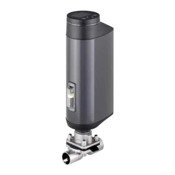
bürkert 3363 Schnellstartanleitung
Elektromotorisches membranregelventil
Vorschau ausblenden
Andere Handbücher für 3363:
- Bedienungsanleitung (176 Seiten) ,
- Schnellstartanleitung (57 Seiten) ,
- Zusatzanleitung (12 Seiten)

Verwandte Anleitungen für bürkert 3363


Inhaltszusammenfassung für bürkert 3363
- Seite 66 Typ 3363, 3364, 3365 Inhaltsverzeichnis DER QUICKSTART .............. 66 Membran und Antrieb montieren....... 84 Drehen des Antriebs ..........88 1.1 Begriffsdefinition ............66 Haltevorrichtung ............88 Darstellungsmittel ............67 ELEKTRISCHE INSTALLATION ........... 89 BESTIMMUNGSGEMÄSSE VERWENDUNG ...... 68 Elektrische Installation mit Rundsteckverbinder ..89 GRUNDLEGENDE SICHERHEITSHINWEISE .....
-
Seite 67: Der Quickstart
Typ 3363, 3364, 3365 Der Quickstart DER QUICKSTART 11.3 Displayansichten ............. 116 11.4 Beschreibung der Symbole ........116 Der Quickstart enthält in Kurzform die wichtigsten Informationen und Hinweise für den Gebrauch des Geräts. Die ausführliche 12 MANUELLE BETÄTIGUNG DES VENTILS ......118 Beschreibung finden Sie in der Bedienungsanleitung für den Typ 12.1 Ventil elektrisch betätigen ........118 3363, 3364 und 3365. -
Seite 68: Darstellungsmittel
Typ 3363, 3364, 3365 Der Quickstart • AG2: Antriebsgröße 2 mit einer Nennkraft von 2500 N für Mem- Verweist auf Informationen in dieser Bedienungsan- brangröße 8...40 leitung oder in anderen Dokumentationen. AG3: Antriebsgröße 3 mit einer Nennkraft von 11500 N für Mem- brangröße 40...100 ▶ Markiert eine Anweisung zur Vermeidung einer Gefahr. → • In dieser Anleitung steht die Einheit bar für den Relativdruck. Der Markiert einen auszuführenden Arbeitsschritt. Absolutdruck wird gesondert in bar(abs) angegeben. Markiert ein Resultat. Darstellungsmittel MENUE Darstellung für Software-Oberflächentexte. GEFAHR! Warnt vor einer unmittelbaren Gefahr. ▶ Bei Nichtbeachtung sind Tod oder schwere Verletzungen die Folge. WARNUNG! Warnt vor einer möglichen, gefährlichen Situation. -
Seite 69: Bestimmungsgemässe Verwendung
Bestimmungsgemäße Verwendung BESTIMMUNGSGEMÄSSE GRUNDLEGENDE VERWENDUNG SICHERHEITSHINWEISE Bei nicht bestimmungsgemäßem Einsatz des elektromotorischen Diese Sicherheitshinweise berücksichtigen keine bei Montage, Membranregelventils vom Typ 3363, 3364 und 3365 können Betrieb und Wartung auftretenden Zufälle und Ereignisse. Der Gefahren für Personen, Anlagen in der Umgebung und die Umwelt Betreiber ist dafür verantwortlich, dass die ortsbezogenen Sicher- entstehen. heitsbestimmungen, auch in Bezug auf das Personal, eingehalten Das elektromotorische Membranregelventil ist für die Steu- werden. - Seite 70 Typ 3363, 3364, 3365 Grundlegende Sicherheitshinweise ▶ Ist die Ventilstellung bei Stromausfall sicherheitstechnisch ▶ Am Gerät keine inneren oder äußeren Veränderungen vor- relevant: Nur Geräte einsetzen, die den SAFEPOS energy- nehmen und nicht mechanisch belasten. pack (optionalen Energiespeicher) besitzen. ▶ Schweres Gerät ggf. nur mit Hilfe einer zweiten Person und ▶ Im Menü SAFEPOS eine für den Prozess sichere Ventilstellung mit geeigneten Hilfsmitteln transportieren, montieren und wählen. demontieren. ▶ Gegen unbeabsichtigte Betätigung sichern. Gefahr durch laute Geräusche. ▶ Nur geschultes Fachpersonal darf Installations- und Instand- ▶ Abhängig von den Einsatzbedingungen können durch das haltungsarbeiten ausführen.
-
Seite 71: Allgemeine Hinweise
Typ 3363, 3364, 3365 Allgemeine Hinweise ALLGEMEINE HINWEISE AUFBAU UND FUNKTION Das elektromotorische Membranregelventil besteht aus einem Kontaktadresse elektromotorisch angetriebenen Linearantrieb und einem Deutschland Membranventilgehäuse. Bürkert Fluid Control Systems Seitlich im Linearantrieb ist die elektronische Ansteuerung und der Sales Center „SAFEPOS energy-pack“ untergebracht. -
Seite 72: Anzeige Des Gerätezustands
Typ 3363, 3364, 3365 Aufbau und Funktion Bei Gerätestatus die von „Normal“ abweichen: Blinken im Wechsel Druckausgleichs- der Farben für Ventilstellung und Gerätestatus. element / Zugang zur mechanischen Blinddeckel oder Display- Ventil- Farbe für Farbe für Gerätestatus Handbetätigung modul mit Statusanzeige stellung Ventil- SAFEPOS energy- und Bajonettverschluss stellung pack (optional) Antriebsdeckel Nur bei Geräten mit Prozessreglerfunktion Antriebsgehäuse Elektrische Anschlüsse offen gelb*... -
Seite 73: Technische Daten
Typ 3363, 3364, 3365 Technische Daten TECHNISCHE DATEN Typschild Folgende produktspezifischen Angaben sind auf dem Durchflusskapazität Typschild angegeben: Werkstoff Ventilgehäuse, • Spannung [V] (Toleranz ±10 %) und Stromart Leitungsanschluss Da (ø außen) Di (ø innen) • Membranwerkstoff und Werkstoff des Ventilgehäuses Maximal zulässiger Mediumsdruck, • Feldbusstandard Membranwerkstoff, Membrangröße Spannung, Gleichstrom, maximale Stromstärke, • Membrangröße Antriebsgröße • Durchflusskapazität Typ, Funktion (Stellungsregler / Prozessregler), Feldbusstandard • Antriebsgröße • Leitungsanschluss büS... -
Seite 74: Zusatztypschild Für Ul-Zulassung (Beispiel)
Typ 3363, 3364, 3365 Technische Daten 6.3.1 Zusatztypschild für UL-Zulassung Firmenzeichen (Beispiel) Werkstoff Schmelze 1.4435 Type AE33-SA 316L(VP) XXXXXXXX Nenndruck PN16 / CWP150 Power Supply SELV / PELV only! LISTED Anschluss- Process Control Equipment nennweite und E238179 Rohrmaße Fertigungsnummer / XXXXXXXXXX Auftragsnummer / Code Oberflä- Bild 4: Zusatztypschild für UL-Zulassung... -
Seite 75: Zulässige Temperaturbereiche
Typ 3363, 3364, 3365 Technische Daten 6.5.1 Zulässige Temperaturbereiche WARNUNG! Die zulässigen Temperaturbereiche für Medium und Verminderte Dichtschließfunktion bei zu hohem Umgebung sind von verschiedenen Faktoren abhängig: Betriebsdruck. • Mediumstemperatur: abhängig vom Werkstoff des Ven- Da das Membranregelventil gegen den Mediumsstrom tilgehäuses und Membranwerkstoff. Siehe Kapitel „6.5.2“. geschlossen wird, kann ein zu hoher Betriebsdruck bewirken, • Umgebungstemperatur: abhängig von der Mediums- dass das Ventil nicht dicht schließt. temperatur. Siehe „Bild 8“ und „Bild 9“. ▶ Der Betriebsdruck darf nicht höher sein als der auf dem Für die Ermittlung der zulässigen Temperaturen müssen... - Seite 76 Typ 3363, 3364, 3365 Technische Daten Zulässige Mediumstemperatur für Membranwerkstoff Zulässige Mediumstemperatur für Ventilgehäuse aus Kunststoff Die zulässige Mediumstemperatur für Ventilgehäuse aus Kunst- Zulässiger Temperaturbereich für stoff ist vom Betriebsdruck abhängig. Medium Membranwerkstoff minimal maximal Dampfsterilisation EPDM (AB), PTFE/ -10 °C +130 °C +140 °C/60 min. EPDM (EA) EPDM (AD), -5 °C +143 °C +150 °C/60 min. advanced PTFE/ EPDM (EU) GYLON / EPDM -5 °C...
- Seite 77 Typ 3363, 3364, 3365 Technische Daten 140 150 140 150 Mediumstemperatur [°C] Mediumstemperatur [°C] Bild 8: Temperaturdiagramm AG2 Bild 9: Temperaturdiagramm AG3 Beschreibung Pos. Beschreibung Geräte ohne Modul Geräte ohne Modul Geräte mit Display-Modul Geräte mit SAFEPOS energy-pack* Geräte mit Display-Modul mit/ohne SAFEPOS Geräte mit SAFEPOS energy-pack* energy-pack* oder mit Feldbus-Gateway mit/ohne Display-Modul Geräte mit Feldbus-Gateway mit/ohne Display-Modul * Die Lebensdauer des SAFEPOS energy-packs ist von der Medium- mit/ohne SAFEPOS energy-pack* stemperatur und der Umgebungstemperatur abhängig (siehe Kapitel * D ie Lebensdauer des SAFEPOS energy-packs ist von der Medium- Elektrische Daten).
-
Seite 78: Allgemeine Technische Daten
Typ 3363, 3364, 3365 Technische Daten Allgemeine Technische Daten Elektrischer mit Anschlussklemmen (nur AG2) oder Anschluss: Rundstecker Werkstoffe Antriebboden: PPS (AG2) / 1.4308 (AG3) Schalldruck- <70 dB (A), kann abhängig von den Einsatzbe- Antriebsgehäuse: Aluminium EN AW 6063 pegel: dingungen höher sein. pulverbeschichtet Kvs-Wert: siehe Typschild oder Bedienungsanleitung Sichtfenster: PC Antriebsdeckel: PPS (AG2) / PC (AG3) 6.6.1 Elektrische Daten Ventilgehäuse GEFAHR! Metall: Feinguss (VG), Schmiedestahl (VS), Rohrumformgehäuse (VP) Elektrischer Schlag. Kunsttoff: PP, PVC und PVDF Die Schutzklasse III wird nur gewährleistet bei Verwendung... - Seite 79 Typ 3363, 3364, 3365 Technische Daten Betriebsspannung: 2 4 V ±10 %, max. Restwelligkeit Energiespeicher SAFEPOS energy-pack 10 % A ufladezeit: maximal 120 Sekunden (abhängig von den Einsatzbedingungen) Betriebsstrom [A]*: L ebensdauer: bis zu 15 Jahre (abhängig von den Einsatzbedin- Typisch (ohne Ladestrom Maximal (zur Auslegung gungen). Die Lebensdauer von 5 Jahren wurde unter folgenden SAFEPOS energy-pack) des Netzteils) Bedingungen ermittelt: Umgebungstemperatur 30 °C (AG2) / 65 °C (AG3) Mediumstemperatur 165 °C 3,5 A Einschaltdauer 100 % Betriebsdruck 5 bar Der Betriebsstrom kann bei Bedarf reduziert werden: Nennweite DN32 (AG2) / DN65 (AG3) 1. Stellgeschwindigkeit X.TIME reduzieren. 2. Geräte mit SAFEPOS energy-pack: Funktion „Control HINWEIS! if ready“ einstellen. Siehe auch Bedienungsanleitung.
- Seite 80 Typ 3363, 3364, 3365 Technische Daten Frequenz: Messbereich bis 1000 Hz Der Digitaleingang, die Digitalausgänge und der Analo- Eingangswiderstand > 30 kΩ gausgang sind zur Betriebsspannung nicht galvanisch Auflösung 0,1 % vom Messwert getrennt. Sie beziehen sich auf das Potential GND der Eingangssignal > 300 mVss Betriebsspannung. Signalform Sinussignal, Strombegrenzung: Bei Überlast wird die Ausgangs- Rechtecksignal, spannung reduziert. Dreiecksignal Pt 100: Messbereich –20...+220 °C Auflösung 0,01 °C Messstrom 1 mA Analoger Ausgang (optional) Max. Strom: 1 0 mA (für Spannungsausgang 0...5/10 V) Bürde (Last): 0 ...800 Ω (für Stromausgang 0/4...20 mA) Digitalausgänge...
-
Seite 81: Montage Des Ventils
Typ 3363, 3364, 3365 Montage des Ventils MONTAGE DES VENTILS Einbaulage der Membranregelventile Abhängig vom Ventilgehäuse ist die Einbaulage für das Memb- WARNUNG! ranregelventil unterschiedlich. Verletzungsgefahr bei unsachgemäßer Montage. Eine der Entlastungsbohrungen im Membransockel, zur ▶ Die Montage darf nur geschultes Fachpersonal mit geeigne- Überwachung der Leckage muss am tiefsten Punkt sein. tem Werkzeug durchführen. ▶ Anlage gegen unbeabsichtigtes Betätigen sichern. 7.1.1 Einbaulage für 2-Wege-Gehäuse ▶ Nach der Montage für einen kontrollierten Wiederanlauf des Einbaulage: beliebig; bevorzugt Antrieb nach oben. Prozesses sorgen. Reihenfolge beachten! 1. Die Versorgungsspannung anlegen. -
Seite 82: Einbaulage Für T-Gehäuse
Typ 3363, 3364, 3365 Montage des Ventils 7.1.2 Einbaulage für T-Gehäuse Montage von Geräten mit Gewinde- muffenanschluss, Flanschanschluss, Empfohlene Einbaulage: Clamp-Anschluss, Klebeanschluss Bei Zuführung von Medium Bei Entnahme von Medium HINWEIS! Beschädigung der Membran. ▶ Zur Vermeidung von Schäden, muss das Gerät bei der Mon- tage im Betriebszustand HAND sein. Bei Geräten im Auslieferungszustand ist der Betriebszustand HAND bereits eingestellt. -
Seite 83: Nach Der Montage
Typ 3363, 3364, 3365 Montage des Ventils → Das Gerät elektrisch anschließen. Die Position der Auslieferungszustand für Geräte mit Schweißanschluss Anschlüsse kann durch Drehen des Antriebs um 360° ausge- Die Geräte werden demontiert ausgeliefert. richtet werden. Beschreibung siehe Kapitel „7.5 Drehen des Betriebszustand: HAND. Antriebs“. Position des Antriebs: Ventil geöffnet. Die Beschreibung des elektrischen Anschlusses finden Die Montage gliedert sich in folgende Schritte: Sie in Kapitel „8 Elektrische Installation“ 1. V entilgehäuse in demontiertem Zustand einschweißen. 7.2.1 Nach der Montage Für Geräte mit Bodenablassgehäuse sind beim Ein- →... -
Seite 84: Bodenablassgehäuse Schweißen
Typ 3363, 3364, 3365 Montage des Ventils 7.3.2 Bodenablassgehäuse schweißen GEFAHR! Empfehlungen: Verletzungsgefahr durch hohen Druck. Reihenfolge beachten: ▶ Vor Arbeiten an der Anlage den Druck abschalten und Lei- 1. D as Bodenablassgehäuse an den Behälterboden schweißen, tungen entlüften oder entleeren. bevor der Behälter aufgebaut wird. Das Schweißen an einen fertig montierten Behälter ist möglich aber schwieriger. -
Seite 85: Membran Und Antrieb Montieren
Typ 3363, 3364, 3365 Montage des Ventils 2. Bodenablassgehäuse in die Rohrleitung schweißen: → Bodenablassgehäuse einschweißen. Auf spannungsfreie und schwingungsarme Montage achten! Nach dem Einschweißen: Druckstück Druckstück mit eingelegtem Die Membran und den Antrieb montieren. Einlegeteil Einlegeteil Membran und Antrieb montieren Bild 13: Einlegeteil in Druckstück einlegen →... -
Seite 86: Antrieb Auf Das Ventilgehäuse Montieren Und Elektrisch Anschließen
Typ 3363, 3364, 3365 Montage des Ventils 7.4.1 Antrieb auf das Ventilgehäuse montieren M.SERVICE ausführen mit Tasten im Gerät: und elektrisch anschließen Die 2 Tasten zum Auslösen der M.SERVICE sind unter dem Blinddeckel. HINWEIS! Geräte mit ATEX-Zulassung oder IECEx-Zulassung sind Beschädigung der Membran. mit einem Magnetschloss gesichert. ▶ Zur Vermeidung von Schäden muss das Gerät bei der Das Abnehmen des Deckels ist in der Zusatzanleitung der Montage im Betriebszustand HAND sein. Die Position des... - Seite 87 Typ 3363, 3364, 3365 Montage des Ventils M.SERVICE ausführen am Display des Geräts: WARNUNG! Displaybedienung: Tastenfunktionen Verletzungsgefahr durch Nichtbeachten des wählen, bestätigen zurück Anziehdrehmoments. aktivieren Das Nichtbeachten des Anziehdrehmoments ist wegen einer Zum Auslösen der Funktion M.SERVICE müssen Sie zur Detail- möglichen Beschädigung des Geräts gefährlich. ansicht Wartung für Stellungsregler wechseln. ▶ Anziehdrehmoment beachten. So wechseln Sie von Ansicht 1 zur Detailansicht: → Muttern über Kreuz bis 1/3 des Anziehdrehmoments →...
-
Seite 88: Drehen Des Antriebs
Typ 3363, 3364, 3365 Montage des Ventils Drehen des Antriebs Haltevorrichtung Um den Ventilantrieb vor Schäden durch Kräfte und HINWEIS! Schwingungen zu schützen, wird eine Haltevorrichtung Beschädigung der Membran. empfohlen. Diese ist als Zubehör erhältlich. Siehe Bedie- ▶ Damit die Membran nicht beschädigt wird, muss das Ventil nungsanleitung auf der Homepage country.burkert.com beim Drehen des Antriebs offen sein. 7.4.2 Nach der Montage Die Position der Anschlüsse kann durch Drehen des Antriebs um → Nach der Montage die erforderlichen Grundeinstellungen und 360° ausgerichtet werden. Anpassungen für das elektromotorische Membranregelventil →... -
Seite 89: Haltevorrichtung
Typ 3363, 3364, 3365 Elektrische Installation ELEKTRISCHE INSTALLATION Bei Geräten mit montierter Haltevorrichtung ist das Das elektromotorische Membranregelventil gibt es in Drehen des Antriebs nicht möglich. 2 Anschlussvarianten: • Mit Rundsteckverbinder (Multipolvariante) Haltevorrichtung → • Kabelverschraubung mit Anschlussklemmen Haltevorrichtung wie im Bild dargestellt am Sechskant des Antriebs anbringen. Signalwerte Betriebsspannung: 24 V ... -
Seite 90: Elektrische Installation Mit Rundsteckverbinder
Typ 3363, 3364, 3365 Elektrische Installation 8.1.2 Beschreibung der Rundsteckverbinder HINWEIS! AG2 Variante Zur Gewährleistung der elektromagnetischen Verträglichkeit (EMV) muss die Funktionserde mit einer kurzen Leitung (max. X3 – Rundstecker M12, 1 m) geerdet werden. Die Funktionserde muss den Querschnitt 5-polig, A-codiert von mindestens 1,5 mm² besitzen. Betriebsspannung AG2 Verwendung des Sollwerteingangs 4...20 mA und büS/CANopen Fällt bei einer Reihenschaltung mehrerer Geräte die elekt- X1 – Rundstecker M12, rische Versorgung eines Geräts in dieser Reihenschaltung 8-polig, A-codiert aus, wird der Eingang des ausgefallenen Geräts hochohmig. - Seite 91 Typ 3363, 3364, 3365 Elektrische Installation AG3 Variante Rundsteck- verbinder Analog büS/ Analog büS/ X2 – Rundbuchse M12, Feldbus- CANopen Feldbus- CANopen 5-polig, A-codiert Gateway Gateway Eingangssignale Prozessistwert optional bei Geräten mit Prozessregelfunktion X3 – Rundstecker M12, 5-polig, A-codiert büS/CANopen Tab. 8: Verwendung Rundsteckverbinder AG2/AG3 →...
-
Seite 92: X1 - Rundstecker M12, 8-Polig, A-Codiert
Typ 3363, 3364, 3365 Elektrische Installation 8.1.3 X1 – Rundstecker M12, 8-polig, A-codiert 8.1.4 X2 – Rundbuchse M12, 5-polig, A-codiert, Eingangssignale Prozessistwert (nur Pin Aderfarbe* Belegung (aus Sicht des Geräts) bei Prozessreglerfunktion) Eingangssignale der Leitstelle (z. B. SPS) Ader- Geräte- Äußere Signalart* Pin Belegung... -
Seite 93: X3 - Rundstecker M12, 5-Polig, A-Codiert, Betriebsspannung Ag2 Und Büs/Canopen Netzwerk
Typ 3363, 3364, 3365 Elektrische Installation 8.1.5 X3 – Rundstecker M12, 5-polig, A-codiert, Ader- Geräte- Äußere Signalart* Pin Belegung Betriebsspannung AG2 und büS/CANopen farbe seitig Beschaltung Netzwerk Frequenz 1 braun nicht belegt - extern Elektrische Installation mit oder ohne büS-Netzwerk: 2 weiß... -
Seite 94: Pin Adernfarbe Mit Büs
Typ 3363, 3364, 3365 Elektrische Installation 8.1.6 X3 – Rundstecker M12, 5-polig, büS/ 8.1.7 X4 – Rundstecker M12, L-codiert, 5-polig, CANopen Netzwerk AG3 Aktorversorgung AG3 Pin Aderfarbe* Belegung Bei Ausführung mit Feldbus-Gateway ist dieser braun +24 V ±10 %, max. Restwelligkeit 10 % Anschluss optional für Service-büS oder einen büS- weiß nicht anschließen fähigen extern versorgten Sensor nutzbar. blau Pin Adernfarbe schwarz nicht anschließen... - Seite 95 Typ 3363, 3364, 3365 Elektrische Installation ACHTUNG! FE Funktionserde Zur Gewährleistung der elektromagnetischen Verträglichkeit Feldbus-Gateway (EMV) ist ein geschirmtes Ethernetkabel zu verwenden. Erden Sie den Kabelschirm beidseitig, d. h. an jedem der angeschlos- senen Geräte. Steckverbinder Das Metallgehäuse des M12-Rundsteckverbinders ist mit dem Antriebsgehäuse verbunden, deshalb muss die Funktionserde am Antriebsgehäuse geerdet werden. Für die Erdung eine kurze Buchse M12, 4-polig Belegung Leitung (max. 1m) mit einem Querschnitt von mindestens 1,5 mm Ethernet, Transmit + verwenden.
-
Seite 96: Elektrische Installation Mit Kabelverschraubung (Nur Ag2)
Typ 3363, 3364, 3365 Elektrische Installation Elektrische Installation mit 8.3.2 Zugang zu den Anschlussklemmen Kabelverschraubung (nur AG2) Für den Zugang zu den Klemmen das Gerät wie nachfolgend beschrieben öffnen. 8.3.1 Sicherheitshinweise 1. Display-Modul oder Blinddeckel abnehmen: WARNUNG! ACHTUNG! Verletzungsgefahr bei unsachgemäßer Installation. -
Seite 97: Kabel Anschließen
Typ 3363, 3364, 3365 Elektrische Installation Bei Gerätevariante mit Display-Modul: 8.3.3 Kabel anschließen → Das Verbindungskabel zur HMI-Schnittstelle ausstecken. → Kabel durch die Kabelverschraubung schieben. 2. LED- und Speichermodul entnehmen: → HINWEIS! Die 2 Befestigungsschrauben entfernen (Außensechskant- schlüssel, Schlüsselweite 3 mm). Für Anschluss an Federzugklemmen beachten. → Das LED- und Speichermodul beidseitig am Metallgehäuse ▶... -
Seite 98: Klemmenbelegung - Betriebsspannung Und Büs-Netzwerk
Typ 3363, 3364, 3365 Elektrische Installation 8.3.4 Klemmenbelegung – Eingangssignal der Anschlussklemmen Leitstelle (z. B. SPS) Klemme Belegung (aus Sicht des Geräts) Sollwert + (0/4...20 mA oder 0...5/10 V) zur Betriebsspannung galvanisch getrennt Sollwert – 0...5 V (log. 0) Digitaleingang Kabelverschraubungen 10...30 V (log. 1) Digitaleingang GND bezogen auf Betriebsspannung GND (Klemme GND) Tab. 14: Klemmenbelegung – Eingangssignal der Leitstelle (z. B. SPS) FE Funktionserde 8.3.5 Klemmenbelegung –... -
Seite 99: Klemmenbelegung - Prozessistwerteingang (Nur Bei Prozessreglerfunktion)
Typ 3363, 3364, 3365 Elektrische Installation 8.3.7 Klemmenbelegung – Prozessistwert- * Elektrische Installation büS-Netzwerk: eingang (nur bei Prozessreglerfunktion) Die Klemmen 1, 2 und 3 (CAN-Schnittstelle) sind für den Anschluss des büS-Netzwerks. Geräte- Äußere Signalart* Klemme Belegung Klemme 1 ist intern mit Klemme 9 gebrückt, jedoch seitig Beschaltung nicht für die Betriebsspannung ausgelegt. 4...20 mA +24 V Versorgung - intern Transmitter Transmitter versorgt 8.3.6 Klemmenbelegung - Ausgangssignale PV1: nicht belegt zur Leitstelle (z.B. -
Seite 100: Gerät Schließen
Typ 3363, 3364, 3365 Elektrische Installation 8.3.8 Gerät schließen Geräte- Äußere Signalart* Klemme Belegung seitig Beschaltung HINWEIS! Frequenz nicht belegt Beschädigung oder Funktionsausfall durch Eindringen von - extern PV1: Takt-Eingang + 15 Takt + Schmutz und Feuchtigkeit. versorgt nicht belegt PV2: nicht belegt Vor dem Schließen des Geräts zur Sicherstellung der Schutzart IP65 und IP67 beachten: PV3: Takt-Eingang – 13 Takt –... -
Seite 101: Inbetriebnahme
Typ 3363, 3364, 3365 Inbetriebnahme INBETRIEBNAHME 1. Antriebsdeckel montieren → Antriebsdeckel auf das Antriebsgehäuse setzen. WARNUNG! → Die 4 Befestigungsschrauben (Innensechsrundschrauben T25) zunächst von Hand über Kreuz leicht eindrehen und Verletzungsgefahr bei unsachgemäßem Betrieb. anschließend festziehen (Anziehdrehmoment: 5,0 Nm). Nicht sachgemäßer Betrieb kann zu Verletzungen sowie 2. LED- und Speichermodul einsetzen Schäden am Gerät und seiner Umgebung führen. → LED- und Speichermodul einlegen und mit den 2 Befestigungs- ▶... -
Seite 102: Grundeinstellungen
Typ 3363, 3364, 3365 Inbetriebnahme 9.2.2 Grundeinstellungen Prozessregelung • Einstellung am Display des Geräts (optional) Nur bei Geräten mit Display-Modul möglich. Art der Grundeinstellung Werkseitige Voreinstellung (Reihenfolge beachten) • Mit 2 kapazitiven Tasten im Gerät die Stellungsregelung 1. Sicherheitsposition einstellen Close anpassen Nur bei Geräten ohne Display-Modul möglich. 2. Physikalische Einheit für Prozess- Prozent regelung wählen... -
Seite 103: Sicherheitsposition Einstellen
SAFEPOS wählen. 2) Die Funktion P.TUNE unterstützt durch selbsttätiges optimieren der Prozessparameter das Einrichten der Prozessregelung. → FUNCTION wählen. Die Feinjustierung der Prozessparameter ist in der Softwarebe- Folgende Sicherheitspositionen stehen zur Auswahl: schreibung zu Typ 3363 beschrieben. Close Ventil dicht geschlossen. Open Ventil geöffnet. Frei definierte Sicherheitsposition. User-Defined Die Eingabe der Position im Menü User-Defined ist nachfolgend beschrieben. -
Seite 104: Anpassung Der Stellungsregelung Bei Ag2
Typ 3363, 3364, 3365 Inbetriebnahme Anpassung der Stellungsregelung bei Eingabe der frei definierten Sicherheitsposition (nur bei Auswahl von Sicherheitsposition User-Defined). → Position wählen. Bei Geräten mit montiertem Ventilgehäuse im Auslieferungs- → Sicherheitsposition eingeben zustand ist die Stellungsregelung werkseitig voreingestellt (0 % = geschlossen, 100 % = geöffnet). und ausgeführt. Beim Ausführen der Funktion M.Q0.TUNE wird die Stellungsre- Sie haben die Sicherheitsposition eingestellt. -
Seite 105: Anpassung Mit Tasten Im Gerät
Typ 3363, 3364, 3365 Inbetriebnahme 9.4.1 Anpassung der Stellungsregelung - M.Q0. 9.4.2 Anpassung mit Tasten im Gerät TUNE Die 2 Tasten zum Herantasten an den Dichtschließpunkt und zum Auslösen der M.Q0.TUNE sind unter dem Blinddeckel. HINWEIS! Geräte mit ATEX-Zulassung oder IECEx-Zulassung sind M.Q0.TUNE ausführen. mit einem Magnetschloss gesichert. ▶ M.Q0.TUNE ausführen um sicherzustellen, dass die Memb- ran bei den gegebenen Bedingungen dicht schließt und die Das Abnehmen des Deckels ist in der Zusatzanleitung der Lebensdauer der Membran optimiert wird. elektromotorischen Regelventile mit ATEX-Zulassung und ▶ Nach einem Wechsel von Membran, Antrieb oder Ventilge- IECEx-Zulassung beschrieben. - Seite 106 Typ 3363, 3364, 3365 Inbetriebnahme → → D ie OPEN-Taste und die CLOSE-Taste gleichzeitig 5 s CALIBRATION wählen. → gedrückt halten. M.Q0.TUNE-MANU wählen. D ie Funktion M.Q0.TUNE wird ausgeführt. Es erscheint der Text: Das Gerät berechnet nun die optimale Kraft für das Dicht- „1. Betriebsbedingungen herstellen! schließen des Ventils. 2. Manuell an den Dichtschließpunkt herantasten (Position bei der das Ventil nahezu dicht ist). 9.4.3 Anpassung am PC oder Display des 3. M.Q0.TUNE starten!“ Geräts → Bestätigen. Einstellung am PC über die büS-Serviceschnittstelle und mit der PC-Software Bürkert-Communicator. Dazu ist Es erscheint der Text: das als Zubehör erhältliche USB-büS-Schnittstellen-Set „Stellen Sie die Betriebsbedingungen her: erforderlich. 1. Betriebsdruck! 2. Temperatur!“...
-
Seite 107: Anpassung Der Stellungsregelung Bei Ag3
Typ 3363, 3364, 3365 Inbetriebnahme des Betriebsdrucks empfohlen. Anschließend ist das erneute Mögliche Meldungen Beschreibung Ausführen der TUNE erforderlich. bei Abbruch der M.Q0. TUNE ACHTUNG! Gerätefehler vorhanden. Es liegt ein Fehler vor, durch den TUNE nicht ohne Erfordernis ausführen. das Ausführen der M.Q0.TUNE nicht Nur wenn der Antrieb demontiert bzw. die Membran oder möglich ist. das Ventilgehäuse gewechselt wurde oder bei Undichtigkeit Zeitlimit überschritten. - Seite 108 Typ 3363, 3364, 3365 Inbetriebnahme X.TUNE Geräte mit ATEX-Zulassung oder IECEx-Zulassung sind Anpassung der Stellungsregelung über die Funktion X.TUNE mit einem Magnetschloss gesichert. ausführen siehe Kapitel „9.5.1“ auf Seite 108. Das Abnehmen des Deckels ist in der Zusatzanleitung der Beim Ausführen der Funktion X.TUNE wird die Stellungsregelung an elektromotorischen Regelventile mit ATEX-Zulassung und den physikalischen Hub des verwendeten Stellglieds angepasst und IECEx-Zulassung beschrieben. die benötigte Dichtschließkraft anhand der Voreinstellungen ermittelt. Anlegen von Betriebsdruck ist nicht erforderlich, optimiert jedoch So lösen Sie die Funktion X.TUNE aus: das Ergebnis der X.TUNE. → Die OPEN- und die CLOSE-Taste gleichzeitig 5 s gedrückt Beim Ausführen der X.TUNE leuchtet der LED-Leuchtring orange.
- Seite 109 Typ 3363, 3364, 3365 Inbetriebnahme → Bei Einstellung mit „Bürkert Communicator“ im Navigati- Mögliche Meldungen Beschreibung onsbereich Stellungsregler wählen und auf WARTUNG bei Abbruch der wechseln. X.TUNE → Motorstrom ist zu groß. Der Motorstrom ist für das Ausführen Bei Einstellung am Display, im Startbildschirm auf der Funktion X.TUNE zu groß. KONFIGURATION wechseln, Stellungsregler wählen und Untere Endlage des Die untere Endlage des Ventils kann auf WARTUNG wechseln. Ventils wird nicht vom Wegaufnehmer nicht erkannt Sie sind in der Detailansicht Wartung.
-
Seite 110: Normsignal Für Sollposition Einstellen
Typ 3363, 3364, 3365 Inbetriebnahme Normsignal für Sollposition einstellen Physikalische Einheit für Prozessregelung wählen Einstellmöglichkeit: Mit der PC-Software Bürkert-Communicator oder am Einstellmöglichkeit: Display des Geräts (Option). Mit der PC-Software Bürkert-Communicator oder am Display des Geräts (Option). Displaybedienung: Tastenfunktionen Displaybedienung: Tastenfunktionen wählen, bestätigen zurück aktivieren wählen, bestätigen zurück aktivieren Zum Einstellen des Normsignals müssen Sie zur Detailansicht Zum Wählen der physikalischen Einheit müssen Sie zur Detailan- Parameter für Eingänge / Ausgänge wechseln. sicht Parameter für Prozessregler wechseln. So wechseln Sie von Ansicht 1 zur Detailansicht: So wechseln Sie von Ansicht 1 zur Detailansicht: →... -
Seite 111: Prozesswerte Parametrieren
Typ 3363, 3364, 3365 Inbetriebnahme Prozesswerte parametrieren So skalieren Sie den Prozesssollwert: → SP.scale wählen. Einstellmöglichkeit: → Mit der PC-Software Bürkert-Communicator oder am Minimum und Maximum eingeben. Display des Geräts (Option). Sie haben den Prozesssollwert parametriert. Displaybedienung: Tastenfunktionen 9.8.2 Normsignal für Prozessistwert wählen und wählen, bestätigen zurück skalieren aktivieren Zum Parametrieren der Prozesswerte müssen Sie zur Detailan- So wählen Sie das Normsignal für den Prozessistwert: sicht Parameter für Eingänge / Ausgänge wechseln. -
Seite 112: Prozessregelung Skalieren
Typ 3363, 3364, 3365 Inbetriebnahme Prozessregelung skalieren 9.10 Totband der Prozessregelung einstellen Die Skalierung der Prozessregelung hat Auswirkungen auf fol- gende Funktionen: Einstellmöglichkeit: • Totband der Prozessregelung Mit der PC-Software Bürkert-Communicator oder am • Dichtschließfunktion (CUTOFF), wenn im Menü CUTOFF → Display des Geräts (Option). CUTOFF.type die Prozessregelung (P.CO) gewählt ist. Displaybedienung: Tastenfunktionen Einstellmöglichkeit: Mit der PC-Software Bürkert-Com- wählen, bestätigen zurück municator oder am Display des Geräts (Option). aktivieren Displaybedienung: Tastenfunktionen Zum Einstellen des Totbands müssen Sie zur Detailansicht Para- wählen, bestätigen zurück meter für Prozessregler wechseln. aktivieren So wechseln Sie von Ansicht 1 zur Detailansicht: Zum Skalieren der Prozessregelung müssen Sie zur Detailansicht... -
Seite 113: Prozessregelung Einrichten P.lin, P.tune Ausführen
Typ 3363, 3364, 3365 Inbetriebnahme 9.11 Prozessregelung einrichten P.LIN, Die Funktion P.LIN wird ausgeführt. P.TUNE ausführen 9.11.2 Bei Geräten ohne Display - Einstellmöglichkeit: Korrekturkennlinie aktivieren Mit der PC-Software Bürkert-Communicator oder am Die Aktivierung der Korrekturkennlinie erfolgt mit DIP-Schalter 2, Display des Geräts (Option). der sich unter dem Blinddeckel befindet. Displaybedienung: Tastenfunktionen → Zum Entriegeln den Blinddeckel um gegen den Uhrzeigersinn wählen, bestätigen zurück drehen und abnehmen. aktivieren → DIP-Schalter 2 auf ON stellen. Die Korrekturkennlinie ist nun aktiviert. Zum Einrichten der Prozessregelung müssen Sie zur Detailan- sicht Wartung für Prozessregler wechseln. -
Seite 114: 9.12 Betriebszustand Einstellen
Typ 3363, 3364, 3365 Bedienung 9.12 Betriebszustand einstellen BEDIENUNG WARNUNG! Geräte mit Display-Modul: → Zum Wechsel des Betriebszustands in Ansicht 1 (Startbild- Gefahr durch unsachgemäße Bedienung. schirm) die Menütaste kurz betätigen. Nicht sachgemäße Bedienung kann zu Verletzungen sowie Schäden am Gerät und seiner Umgebung führen. Die Funktion ist nur vorhanden, wenn für die Ansicht 1 das ▶ Das Bedienpersonal muss den Inhalt der Bedienungsanlei- Layout Prozess Control eingestellt ist. Das Layouts kann tung kennen und verstanden haben. im Kontextmenü geändert werden. Zum Öffnen des Kon- ▶ Die Sicherheitshinweise und der bestimmungsgemäße textmenüs die Menütaste lang betätigen. -
Seite 115: 10.2 Bedienelemente
Typ 3363, 3364, 3365 Bedienung 10.2 Bedienelemente 10.1.1 LED-Leuchtring Der transparente LED-Leuchtring, der das Licht der LEDs nach außen transmittiert ist am Blinddeckel oder Display-Modul SIM-Karte angebracht. Zur Anzeige des Gerätezustands leuchtet, blinkt oder blitzt der LED-Leuchtring in einer oder in wechselnden Farben. büS-Service- DIP-Schalter** schnittstelle* D ie Beschreibung der Gerätezustände, Fehler und... -
Seite 116: Open-Taste Und Close-Taste
Typ 3363, 3364, 3365 Displaybedienung (Option) 10.2.2 OPEN-Taste und CLOSE-Taste DISPLAYBEDIENUNG (OPTION) Die Bedienung und Einstellung des Geräts erfolgt an einem Elektrische Ventil öffnen: OPEN-Taste drücken Display mit Touchscreen. Handbetätigung: Ventil schließen: CLOSE-Taste drücken Beim Schließen des Ventils: 11.1 Bedienoberfläche Ventil mit geringer Kraft vorsichtig Digitale schließen, damit die Membran nicht Stellungsan- Informationsleiste beschädigt wird. Taste bei geschlossenem zeige Ventil nicht erneut drücken! Ansicht 1 von 1 Autotune Beschreibung siehe Kapitel „9.4 (M.Q0.Tune und... -
Seite 117: Beschreibung Der Tasten
Typ 3363, 3364, 3365 Displaybedienung (Option) 11.2 Beschreibung der Tasten 11.3 Displayansichten Vom Startbildschirm gelangen Sie in folgende Ansichten: Taste Funktionen • Konfigurationsansicht, mit der linken Navigationstaste . Kurz drücken: Zurück • Vom Benutzer angelegte Ansicht 2...4, mit der rechten Zurücktaste Rücksprung Navigationstaste . Lang drücken: zur Ansicht 1 Startbildschirm (Startbildschirm) Ansicht wechseln Ansicht 1 von 1 Auswahl übernehmen (z. B. bei... -
Seite 118: Beschreibung Der Symbole
Typ 3363, 3364, 3365 Displaybedienung (Option) 11.4 Beschreibung der Symbole Symbole zur Anzeige der Gerätestatus nach NAMUR NE 107 Liegen mehrere Gerätezustände gleichzeitig vor, wird der Geräte- Symbole für Benutzerrechte zustand mit der höchsten Priorität angezeigt. Symbol Beschreibung Priorität Symbol Beschreibung Die Einstellung ist schreibgeschützt und kann nur mit entsprechendem Benutzerrecht/Benutzercode Ausfall, Fehler oder Störung! geändert werden. Aufgrund einer Funktionsstörung im Gerät oder an seiner Peripherie ist kein Regelbe- Benutzer trieb möglich. -
Seite 119: Manuelle Betätigung Des Ventils
Typ 3363, 3364, 3365 Manuelle Betätigung des Ventils MANUELLE BETÄTIGUNG DES Priorität Symbol Beschreibung VENTILS Gerät hat den Regelbetrieb aufgrund eines schweren Fehlers gestoppt. Das Ventil ver- Das Membranregelventil kann auf 2 Arten manuell betätigt harrt in seiner Position. werden: elektrisch oder mechanisch. Energiespeicher aktiv: In der Regel soll für das manuelle Öffnen und Schließen des Ventils Die Versorgungsspannung ist unterbrochen. die elektrische Handbetätigung verwendet werden. Das Gerät wird über den Energiespeicher mit Die mechanische Handbetätigung ist nur zum Öffnen und Schließen Spannung versorgt. des Ventils bei Stromausfall. Die mechanische Handbetätigung darf Bei Betriebszustand AUTOMATIK fährt der nur im stromlosen Zustand verwendet werden. Antrieb in die Sicherheitsposition (siehe 12.1 Ventil elektrisch betätigen Symbol „Sicherheitsposition) -
Seite 120: Geräte Ohne Display-Modul
Typ 3363, 3364, 3365 Manuelle Betätigung des Ventils 12.1.2 Geräte ohne Display-Modul Wechsel in den Betriebszustand HAND: Die 2 Tasten zum Öffnen und Schließen des Ventils befinden sich → Zum Wechsel in den Betriebszustand HAND die unter dem Blinddeckel. Menütaste kurz betätigen. In der Informationsleiste oben ist das HAND-Symbol sichtbar. Die 2 Pfeilsymbole mit der Beschriftung „auf“ und „zu“ sind eingeblendet. Blinddeckel Ventil öffnen oder schließen: entriegeln → Zum Öffnen des Ventils die obere Navigationstaste betätigen. → Zum Schließen des Ventils die untere Navigationstaste DIP-Schalter betätigen. -
Seite 121: 12.2 Ventil Mechanisch Betätigen
Typ 3363, 3364, 3365 Manuelle Betätigung des Ventils 12.2 Ventil mechanisch betätigen Zum Betätigen des Ventils muss das Gerät im Betriebszustand HAND sein. Bei nicht anliegender Versorgungsspannung z. B. bei der Wechsel in den Betriebszustand HAND: Montage oder bei Stromausfall kann die Ventilstellung mit der → mechanischen Handbetätigung geändert werden. DIP-Schalter 4 auf ON stellen. Das Gerät befindet sich nun im Betriebszustand HAND (siehe „Bild 37“). ACHTUNG! Die mechanische Handbetätigung darf nur im stromlosen Zustand verwendet werden, da sonst das Gerät beschädigt werden kann. HINWEIS! Beschädigung von Gerät oder Membran durch mechanische Handbetätigung. - Seite 122 Typ 3363, 3364, 3365 Manuelle Betätigung des Ventils 4a. Nur bei Geräten mit Feldbus-Gateway: Zuerst Feldbus- Druckausgleichse- Gateway auf den Antrieb montieren (Beschreibung siehe lement abschrauben Bedienungsanleitung), danach Blinddeckel oder Display- Modul schließen. 5. Versorgungsspannung anlegen. Drehen Schließen Öffnen Blinddeckel oder Display-Modul entriegeln Ventil öffnen Mechanische drücken und drehen Handbetätigung zum Ändern der Ventilstellung Bild 40: Mechanische Handbetätigung AG3 Blinddeckel oder Display-Modul entfernen: Mechanische Handbetätigung...
- Seite 123 Typ 3363, 3364, 3365 Manuelle Betätigung des Ventils → Die Ventilstellung ist an der mechanischen Stellungsanzeige zu Zum Entriegeln das Display-Modul oder den Blinddeckel erkennen. gegen den Uhrzeigersinn drehen und abnehmen. Beim Display-Modul auf das Verbindungskabel zur HMI- Mechanische Schnittstelle achten. Stellungsanzeige Ventil geöffnet Ventil mechanisch betätigen: ACHTUNG! Die mechanische Handbetätigung darf nur im stromlosen Zustand verwendet werden, da sonst das Gerät beschädigt werden kann. → Zum mechanischen Betätigen des Ventils einen Innensechs- Ventil geschlossen kantschlüssel mit Schlüsselweite 3 mm (AG2) / 5 mm (AG3) benutzen. Bild 41: Mechanische Stellungsanzeige AG2 ACHTUNG! → Nach Erreichen der gewünschten Ventilstellung, den Innen- sechskantschlüssel entfernen. Die mechanische Handbetä-...
-
Seite 124: Feldbus-Gateway
Typ 3363, 3364, 3365 Feldbus-Gateway FELDBUS-GATEWAY WARTUNG, FEHLERBEHEBUNG EtherNet/IP, PROFINET, Modbus TCP Für das Membranregelventil sind folgende Wartungsarbeiten erforderlich. • Nach der ersten Dampfsterilisation oder bei Bedarf Display-Modul → Gehäuseschrauben über Kreuz nachziehen. • Nach maximal 10 Schaltspielen → Membran auf Verschleiß prüfen und falls erforderlich Feldbus- ersetzen. Feldbusan- gateway schluss M12 Schlammartige und abrasive Medien erfordern entspre- (2 Port Ethernet chend kürzere Kontrollintervalle. Switch) • Tausch des Energiespreichers SAFEPOS energy-pack Bild 42: Feldbusgateway mit Display-Modul Das Gerät gibt eine Warnung aus: Die Kapazität des Energie-... -
Seite 125: 14.2 Tausch Der Membran
Typ 3363, 3364, 3365 Wartung, Fehlerbehebung 14.2 Tausch der Membran 14.2.2 Membran demontieren HINWEIS! WARNUNG! Beschädigungen der Membran Verletzungsgefahr durch Mediumaustritt und Druckentladung. ▶ Zur Vermeidung von Schäden muss das Gerät bei Montage Der Ausbau eines Geräts, das unter Druck steht, ist wegen und Demontage der Membran im Betriebszustand HAND plötzlicher Druckentladung oder Mediumsaustritt gefährlich. sein. ▶ Vor dem Ausbau den Druck abschalten und Leitungen ▶ Die Position des Antriebs muss auf „Ventil geöffnet“ stehen. -
Seite 126: Nach Dem Tausch Der Membran
Typ 3363, 3364, 3365 Zubehör → ZUBEHÖR Gehäuseschrauben entnehmen. → Ventilgehäuse abnehmen. 15.1 Kommunikations-Software → Membran ausknöpfen oder ausschrauben (siehe „Tab. 26: Die PC-Software Bürkert-Communicator ist für die Kommuni- Befestigungsarten für Membranen“). kation mit Geräten der Firma Bürkert konzipiert. Bei Membran mit Bajonettverschluss: → Membran durch Eine detaillierte Beschreibung zur Installation und Drehen um 90° lösen und entnehmen. Bedienung der PC-Software finden Sie in der zugehö- → Neue Membran montieren. Beschreibung siehe Kapitel „7.4 rigen Bedienungsanleitung. Membran und Antrieb montieren“ auf Seite 85. Download der Software unter: country.burkert.com 14.2.3 Nach dem Tausch der Membran 15.1.1 USB-Schnittstelle... -
Seite 127: Reinigung
Typ 3363, 3364, 3365 Zubehör Zu Typ 3363, 3364 und 3365 finden Sie im Internet unter VORSICHT! country.burkert.com Verletzungsgefahr durch schweres Gerät. • Weiteres Zubehör (in der Bedienungsanleitung) Beim Transport oder bei Montagearbeiten kann das Gerät herunterfallen und Verletzungen verursachen. REINIGUNG ▶ Schweres Gerät ggf. nur mit Hilfe einer zweiten Person trans- ACHTUNG! portieren, montieren und demontieren. ▶ Geeignete Hilfsmittel verwenden. Zur Reinigung der Geräteoberflächen sind keine alkalischen Reinigungsmittel zugelassen. → Elektrischen Anschluss trennen. → Gerät ausbauen. 16.1 Spülen des Ventilgehäuses Beschreibung siehe Bedienungsanleitung. DEMONTAGE GEFAHR! Verletzungsgefahr durch hohen Druck und Mediumsaustritt. -
Seite 128: Entsorgung
Typ 3363, 3364, 3365 Verpackung, Transport, Lagerung VERPACKUNG, TRANSPORT, ENTSORGUNG LAGERUNG Umweltgerechte Entsorgung HINWEIS! ▶ Nationale Vorschriften bezüglich Entsorgung und Transportschäden. Umwelt beachten. ▶ Elektrische und elektronische Geräte separat Unzureichend geschützte Geräte können durch den Transport sammeln und speziell entsorgen. beschädigt werden. Weitere Informationen unter country.burkert.com. • Gerät vor Nässe und Schmutz geschützt in einer stoßfesten Verpackung transportieren. Falsche Lagerung kann Schäden am Gerät verursachen. • Ein Überschreiten oder Unterschreiten der zulässigen Lager- temperatur vermeiden. Geräte mit Membran: •... - Seite 129 Typ 3363, 3364, 3365 deutsch...
- Seite 200 www.burkert.com...