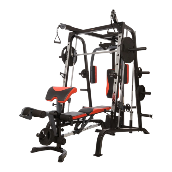
Atlas X2 UWAGI DOTYCZĄCE BEZPIECZEŃSTWA Produkt ten przeznaczony jest wyłącznie do użytku domowego i zaprojektowano go tak, aby zapewnić optymalne bezpieczeństwo. Powinny być przestrzegane następujące zasady: Przed rozpoczęciem treningu skonsultuj się z lekarzem w celu stwierdzenia braku przeciwwskazań do korzystania ze sprzętu do ćwiczeń.
Seite 3
Atlas X2 Lokalizacja naklejek ostrzegawczych...
Seite 4
Atlas X2 Wykaz elementów montażowych Nr 73 - śruba imbusowa (M10 x 3 3/8″), 2 szt. Nr 72 - śruba imbusowa (M10 x 3 1/8″), 2 szt. Nr 71 - śruba imbusowa (M10 x 3″), 2 szt. Nr 105 - śruba imbusowa (M10 x 2 3/4″), 1 szt.
Seite 5
Atlas X2 Nr 79 - śruba zamkowa (M10 x 3 1/2″), 4 szt. Nr 77 - śruba zamkowa (M10 x 3 1/8″), 4 szt. Nr 78 - śruba zamkowa (M10 x 3 3/8″), 8 szt. Nr 67 – podkładka Φ 1 szt.
Atlas X2 Instrukcja montażu Krok 1 (patrz diagram 1) 1) Połącz dwie ramy główne (1) poprzeczką (2). Zabezpiecz każdy koniec poprzeczki dwiema śrubami (79), jednym wspornikiem (36), podkładkami (66) oraz nakrętkami (86). Nie przykręcaj zbyt mocno. Diagram 1...
Seite 7
Atlas X2 Krok 2 (patrz diagram 2) 1) Przyłóż przednią ramę pionową (3) do ramy bazowej (1). Połącz je śrubami (76), wspornikiem (34), podkładkami (66) oraz nakrętkami (86). Nie skręcaj zbyt mocno. 2) Dopasuj odbojnik (59) do otworu montażowego ramy głównej. Przełóż wodzidło (25) przez odbojnik i przykręć...
Seite 9
Atlas X2 Krok 3 (patrz diagram 3) 1) Dopasuj tylną belkę pionową (6) do górnej poprzeczki (2). Teraz dopasuj prowadnicę (8) do poprzeczki (2) od jej dolnej strony. Skręć wszystko przy pomocy śrub (75), wspornika (36), podkładek (66) i nakrętek (86).
Seite 10
Atlas X2 Krok 4 (patrz diagram 4) 1) Połącz słupek suwnicy (7) z bazą suwnicy (8). Wykorzystaj śruby (74), podkładki (66) i nakrętki (86). 2) Nałóż część (14) na słupek (7). Nałóż tylną ramę górną (9) na słupek suwnicy (7) i tylną belkę...
Seite 11
Atlas X2 Krok 5 (patrz diagram 5) 1) Ułóż lewą ramę górną (94) na przedniej belce górnej (15) i przymocuj wykorzystując śruby (77), wspornik (35), podkładki (66) oraz nakrętki (86). 2) Przykręć lewą ramę górną (94) do tylnej ramy górnej używając do tego celu śrub (75), wspornika (101), podkładek (66) i nakrętek (86).
Seite 12
Atlas X2 Krok 6 (patrz diagram 6) 1) W tym momencie już możesz dokręcić wszystkie dotychczas zamontowane śruby i nakrętki. 2) Przyłóż bazę motylka (12) do przedniej części tylnej belki pionowej (6). Przyłóż wspornik krążka (13) do tylnej belki pionowej od jej tylnej części. Dopasuj otwory a następnie połącz używając śrub (75), podkładek (66) i nakrętek (86).
Seite 14
Atlas X2 Krok 7 (patrz diagram 7 i diagram obwodu linki) 1) Przymocuj jeden koniec linki (42) do zatrzasku prawego motylka (11). Przeciągnij linkę przez praw krętlik (20). 2) Przymocuj krążek (57) do jego oprawy za pomocą śruby (69), podkładek (66) i nakrętek (86).
Seite 15
Atlas X2 Krok 8 (patrz diagram 8) 1) Odkręć śrubę (104) i nakrętkę (86) od U-kształtnego łącznika zamontowanego na lince (41). Usuń łącznik (86), dużą podkładkę oraz korek blokady linki. 2) Przełóż koniec linki przez lewy krętlik (99). Zamontuj krążek (57) do oprawy i połącz śrubą (69), podkładkami (66) oraz nakrętką...
Seite 17
Atlas X2 Krok 9 (patrz diagram 9) 1) Włóż jeden koniec linki (102) do otworu na słupku suwnicy (14) i przykręć przy pomocy śruby (68), podkładek (66) i nakrętki (86). 2) Przeciągnij linkę w górę do krążka zamontowanego na tylnej ramie górnej (9), zainstalowanego w kroku 5.
Seite 19
Atlas X2 Krok 10 (patrz diagram 10) 1) Załóż dolną linkę (40) na krążek (57). Zamontuj krążek w dolnym otworze tylnej belki pionowej (6) za pomocą podpórki stóp (16), śruby (73), podkładek (66) oraz nakrętki (86). Podpórkę przykręć do poprzecznej podpórki (2) za pomocą śrub (68), czterech podkładek (66) i nakrętki (86).
Seite 20
Atlas X2 Krok 11 (patrz diagram 11) 1) Sugestia: w tym kroku przyda Ci się pomoc drugiej osoby. Umieść tuleję (27) pomiędzy elementami części (26). Dopasuj otwory, a następnie wsuń sztangę (28) do ramy mechanizmu bezpieczeństwa (26). Zamocuj sztangę do obu końców mechanizmu bezpieczeństwa za pomocą śruby (81).
Seite 22
Atlas X2 Pełny wykaz części Nr Nazwa części Ilość Nazwa części Ilość Rama główna Tuleja przesuwna Mocowanie poprzeczne Obręcz zabezpieczająca Przednia belka pionowa Krążek Lewa rama pionowa Ø 1 ¾” odbojnik Prawa rama pionowa Ø 2 ½” odbojnik Tylna belka pionowa Zacisk sprężynowy...
Seite 23
Atlas X2 53 Ø 1” stożkowa zatyczka Łożysko liniowe 54 2 3/8” x 2” rękaw Rękaw łożyska liniowego M6 x ¼” śruba (Philips)
Seite 24
Atlas X2 Zestaw części do montażu wielofunkcyjnej ławki do ćwiczeń Nr 39 - śruba imbusowa (M10 x 8 1/4″), 1 szt. Nr 38 - śruba imbusowa (M10 x 6 3/4″), 1 szt. Nr 35 - śruba zamkowa (M10 x 2 1/2″), 2 szt.
Seite 25
Atlas X2 Krok 1 (patrz diagram 1) 1) Przyłóż ramę główną (1) do przedniego i tylnego stabilizatora (2 i 3), a następnie połącz części przy pomocy śrub (36) i podkładek (42). Włóż bolec (23) do utworu poniżej głównej ramy. 2) Nałóż przesuwną blokadę (8) na belkę regulacyjną (9). Dopasuj otwory a następnie włóż bolec (23) w celu ustabilizowania pozycji blokady (8).
Seite 26
Atlas X2 Krok 2 (patrz diagram 2) 1) Włóż cztery tuleje (27) do wspornika ramy (6). 2) Przyłóż wspornik oparcia (7) do tylnej strony wspornika ramy (6). Dopasuj otwory i połącz je za pomocą śruby (37) i podkładki (42). Powtórz tę samą procedurą w celu zamontowania drugiej strony.
Seite 27
Atlas X2 Krok 3 (patrz diagram 3) 1) Ułóż oparcie (14) na wsporniku (7). Przykręć je śrubami (40) nie zapominając o podkładkach (43). 2) Ułóż siedzisko (13) na wsporniku (6). Przykręć je śrubami (40) nie zapominając o podkładkach (43). Diagram 3...
Seite 28
Atlas X2 Krok 4 (patrz diagram 4) 1) Nałóż trenażera nóg (5) na główną ramę (1), wtykając go w otwór wspornika. Umocuj całość za pomocą osi (17), śrub (36) oraz podkładek (42). 2) Włóż tubę (10) do połowy otworu w głównej ramie (1). Teraz tuby w ten sam sposób stelażu trenażera nóg (5).
Seite 29
Atlas X2 Krok 5 (patrz diagram 5) 1) Połącz poduszkę pod ramiona (15) ze stelażem (4). Skręć je przy pomocy śrub (41) i podkładek (43). Włóż stelaż (4) do przedniego otworu ramy głównej (1). Użyj pokrętła w celu regulacji położenia poduszki (15).
Seite 31
Atlas X2 Pełny wykaz części Nazwa części Ilość Rama główna Przedni stabilizator Tylny stabilizator 1 Stelaż pod ramiona Trenażer nóg Wspornik siedziska Wspornik oparcia Blokada suwnicy Belka regulacyjna 1 Tuba do montażu piankowej rolki Uchwyt Instrukcja Poduszka siedziska Deska oparcia Oparcie pod ramiona Uchwyt drążka do ćwiczenia ramion...
Atlas X2 Zakres stosowania Suwnica Atlas X2 jest urządzeniem klasy H przeznaczonym wyłącznie do użytku domowego. Nie może być używany w celach terapeutycznych, rehabilitacyjnych i komercyjnych. Dział obsługi klienta: ABISAL Sp. z o.o. ul. Św. Elżbiety 6 41–905 Bytom abisal@abisal.pl www.abisal.pl...
Seite 33
Atlas X2 KARTA GWARANCYJNA Nazwa artykułu: Kod EAN: Data sprzedaży: (Pieczątka i podpis sprzedawcy) WARUNKI GWARANCJI Sprzedawca w imieniu Gwaranta udziela gwarancji na terytorium RP na okres 24 miesięcy od daty sprzedaży. Gwarancja będzie respektowana przez sklep lub serwis po przedstawieniu przez klienta: - czytelnie i poprawnie wypełnionej karty gwarancyjnej z pieczątką...
Seite 34
Atlas X2 Owners manual IMPORTANT SAFETY INFORMATION This product has been designed for home use only and built for optimum safety. Please note the following safety precautions: Before starting any exercise program you should consult your doctor to determine if you have any physical or health conditions that could create a risk to your health and safety, or prevent you from using the equipment properly.
Seite 38
Atlas X2 Smith Machine Assembly Instruction Tools Required Assembling the Machine: Two Adjustable Wrenches and Allen Wrenches. NOTE: It is strongly recommended two or more people assembling this machine to avoid possible injury. STEP 1 (See Diagram 1) 1) Connect the two Base Frames (#1) by a Cross Brace (#2) in the mid-span. Secure each end of The Cross Brace with two M10 x 3 ½”...
Seite 39
Atlas X2 STEP 2 (See Diagram 2) 1) Attach a Front Vertical Frame (#3) to the right Base Frame (#1). Secure it with two M10 x 3” Carriage Bolts (#76), one 5 1/8” x 2 ¾” Bracket (#34), two Ø ¾” Washers (#66), and two M10 Aircraft Nuts (#86).
Seite 41
Atlas X2 STEP 3 (See Diagram 3) 1) Attach the Rear Vertical Beam (#6) to the top of the Cross Brace (#2). Attach the Weight Glide Base (#8) to the Cross Brace from the Bottom. Align the holes. Secure them with two M10 x 3” Carriage Bolts (#76), Ø...
Seite 42
Atlas X2 STEP 4 (See Diagram 4) 1) Attach the Weight Glide Post (#7) onto the Weight Glide Base (#8). Secure it with four M10 x 1” Carriage Bolts (#74), Ø ¾” Washers (#66) and M10 Aircraft Nuts (#86). 2) Slide the Sliding Weight Post (#14) onto the Chromed Post from the top. Place the Rear Upper Frame (#9) onto the Weight Glide Post (#7) and Rear Vertical Beam (#6).
Seite 43
Atlas X2 STEP 5 (See Diagram 5) 1) Place the Left Upper Frame (#94) onto the Front Top Beam (#15). Secure it with two M10 x 3 1/8” Carriage Bolts (#77), one 5 1/8” x 2 3/8” Bracket (#35), two Ø ¾” Washers (#66), and two M10 Aircraft Nuts (#86).
Seite 44
Atlas X2 STEP 6 (See Diagram 6) 1) Securely tighten all Nuts and Bolts previously installed. 2) Attach the Butterfly Base (#12) to the front of Rear Vertical Beam (#6). Attach the Butterfly Pulley Bracket (#13) to the back of the Rear Vertical Beam. Align the holes. Secure them with two M10 x 2 ¾”...
Seite 47
Atlas X2 STEP 7 (See Diagram 7 & Cable Loop Diagram) 1) Attach one end of 87” Butterfly Cable (#42) to the clip on Right Butterfly (#11). Draw the Cable to the right Swivel Pulley Bracket (#20). 2) Attach a Pulley (#57) to the Bracket. Secure it with one M10 x 1 ¾” Allen Bolt (#69), two Ø ¾”...
Seite 48
Atlas X2 STEP 8 (See Diagram 8 & Cable Loop Diagram) 1) Un-install the M10 x 1 1/8” Allen Bolt (#104) and M10 Aircraft Nut (#86) on the U-shaped Connector on one end of the 229” Cable (41). Remove the U-shaped Connector, Big Washer, and Ball Stopper from the Cable.
Seite 50
Atlas X2 STEP 9 (See Diagram 9 & Cable Loop Diagram) 1) Attach one end of the 138” Sliding Weight Post Cable (#102) to the open bracket on the Sliding Weight Post (#14). Secure it with one M10 x 1” Allen Bolt (#68), two Ø ¾” Washers (#66), and one M10 Aircraft Nut (#86).
Seite 52
Atlas X2 STEP 10 (See Diagram 10) 1) Attach the 59” Lower Cable (#40) to a Pulley (#57). Attach the Pulley to the lower opening on the Rear Vertical Beam (#6). Secure it with the Foot Plate (#16), one M10 x 3 3/8” Allen Bolt (#73), two Ø...
Seite 53
Atlas X2 STEP 11 (See Diagram 11) 1) NOTE: Help of another person is strongly recommended for this step. Place the Lifting Sleeve (#27) in between the two Safety Stop Frames (#26). Align the holes. Insert the Weight Bar (#28) into the Safety Stop Frame from one end and through the Lifting Sleeve (#27) to the other Safety Stop Frame on the opposite side.
Atlas X2 Parts List Key No. Description Q’ty Key No. Description Q’ty Base Frame Sliding Sleeve Cross Brace Lock Ring Front Vertical Beam Pulley Left Vertical Frame Ø 1 ¾” Rubber Bumper Right Vertical Frame Ø 2 ½” Rubber Bumper...
Seite 56
Atlas X2 53 Ø 1” Cone-shaped End Cap Linear Bearing 54 2 3/8” x 2” Sleeve Linear Bearing Sleeve M6 x ¼” Philips Screw...
Seite 57
Atlas X2 Multi-Purpose Bench Hardware Pack...
Seite 58
Atlas X2 Multi-Purpose Bench Assembly Instruction Tools Required Assembling the Machine: Two Adjustable Wrenches and Allen Wrenches. NOTE: It is strongly recommended this machine be assembled by two or more people to avoid possible injury. STEP 1 (See Diagram 1) 1) Attach the Main Frame (#1) to the Front &...
Seite 59
Atlas X2 STEP 2 (See Diagram 2) 1) Attach four Bushings (#27) to a Seat Support Frame (#6). 2) Attach a Backrest Support (#7) to the rear of the Seat Support Frame (#6). Align the holes and secure them with one M10 x 1 ¾” Allen Bolt (#37) and ¾” Washer (#42). Repeat the same procedure to install the other side.
Seite 60
Atlas X2 STEP 3 (See Diagram 3) 1) Place the Backrest Board (#14) onto the Backrest Supports (#7). Secure it with four M8 x 2” Allen Bolts (#40) and 5/8” Washers (#43). 2) Place the Seat Pad (#13) onto the Seat Support Frames (#6). Secure it with four M8 x 2” Allen Bolts (#40) and ...
Seite 61
Atlas X2 STEP 4 (See Diagram 4) 1) Attach the Leg Developer (#5) to the open bracket on the Main Frame (#1). Secure it with an Axle (#17), two M10 x ¾” Allen Bolts (#36), and two ¾” Washers (#42).
Seite 62
Atlas X2 STEP 5 (See Diagram 5) 1) Attach the Arm Curl Pad (#15) to the Arm Curl Stand (#4). Secure it with two M8 x 5/8” Allen Bolts (#41) and two 5/8” Washers (#43). Insert the Arm Curl Stand into the front opening on the Main Frame (#1).
Seite 64
Atlas X2 Multi-Purpose Bench Parts List Key No. Description Q’ty Main Frame Front Stabilizer Rear Stabilizer Arm Curl Stand Leg Developer Seat Support Frame Backrest Support Sliding Block Incline Adjustment Bar Foam Tube Arm Curl Handle Manual Seat Pad Backrest Board...
Seite 65
Atlas X2 Terms of references Home gym is use for all body exercises . Home gym Atlas X2 is H class item. Unit is not intended for commercial use therapy or rehabilitation. Consumer service department: ABISAL Sp. z o.o. ul. Św. Elżbiety 6 41–905 Bytom...
Atlas X2 BEZPEČNOSTNÍ POKYNY Výrobek je určen výlučně k domácímu použití a byl navržen tak, aby byla zajištěna optimální bezpečnost. Dodržujte následující pokyny: V případě možnosti existence zdravotních překážek ve využívání tohoto zařízení se před započetím tréninku poraďte s lékařem.
Seite 67
Atlas X2 Umístění bezpečnostních nálepek...
Seite 68
Atlas X2 Seznam montážních částí Č. 73 – imbusový šroub (M10 x 3 3/8″), 2 ks. Č. 72 – imbusový šroub (M10 x 3 1/8″), 2 ks Č. 71 – imbusový šroub (M10 x 3″), 2 ks Č. 105 – imbusový šroub (M10 x 2 3/4″), 1 ks Č.
Seite 69
Atlas X2 Č. 79 – blokační šroub (M10 x 3 1/2″), 4 ks Č. 77 – blokační šroub (M10 x 3 1/8″), 4 ks Č. 67 – podložka Č. 78 – blokační šroub (M10 x 3 3/8″), 8ks Φ 1 1/2″), 2 ks...
Seite 70
Atlas X2 Návod montáže Krok 1 (viz obr. 1) 1) Spojte dva hlavní rámy (1) se zpevňujícím příčníkem (2). Každý konec příčníku zabezpečte dvěma šrouby (79), jednou vzpěrou (36), podložkami (66) a matkami (86). Šrouby a matky příliš nedotahujte. Obr. 1...
Seite 71
Atlas X2 Krok 2 (viz obr. 2) 1) Přiložte přední svislou tyč (3) k hlavnímu rámu (1). Spojte je pomocí šroubů (76), zpevňující destičky (34), podložek (66) a matek (86). Šrouby a matky příliš nedotahujte. 2) Nárazník (59) přiložte k montážnímu otvoru hlavního rámu. Protáhněte kolejnici (25) nárazníkem a připevněte ji k hlavnímu rámu pomocí...
Seite 73
Atlas X2 Krok 3 (viz obr. 3) 1) Přiložte zadní svislý rám (6) ke zpevňujícímu příčníku (2). Nyní přiložte základnu pojezdu závaží (8) ke spodní straně příčníku (2). Vše zpevněte pomocí šroubů (75), zpevňující destičky (36), podložek (66) a matek (86).
Seite 74
Atlas X2 Krok 4 (viz obr. 4) 1) Spojte sloupek pojezdu závaží (7) se základnou pojezdu závaží (8) pomocí šroubů (74), podložek (66) a matek (86). 2) Nasaďte část (14) na sloupek (7). Nasaďte zadní horní rám (9) na sloupek pojezdu závaží (7) a zadní...
Seite 75
Atlas X2 Krok 5 (viz obr. 5) 1) Položte levý horní rám (94) na přední horní profil (15) a spojte je pomocí šroubů (77), zpevňující destičky (35), podložek (66) a matek (86). 2) Připevněte levý horní rám (94) k zadnímu hornímu rámu pomocí šroubů (75), zpevňující destičky (101), podložek (66) a matek (86).
Seite 76
Atlas X2 Krok 6 (viz obr. 6) 1) V tomto okamžiku můžete dotáhnout všechny do té doby použité šrouby a matky. 2) Přiložte základnu „motýlku” (12) k přední části zadního svislého profilu (6). Přiložte rám kladky „motýlku” (13) ze zadní části zadního svislého profilu. Dopasujte otvory a dále vše spojte pomocí...
Seite 78
Atlas X2 Krok 7 (viz obr. 7 a nákres obvodu lanek) 1) Připevněte jeden konec lanka (42) k pravému rameni „motýlku” (11). Protáhněte lanko pravým držákem kladky (20). 2) Připevněte kladku (57) do jejího držadla pomocí šroubu (69), podložek (66) a matek (86).
Seite 79
Atlas X2 Krok 8 (viz obr. 8) 1) Odšroubujte šroub (104) a matku (86) od U-karabiny připevněné k lanku (41). 2) Přeložte konec lanka přes levý otočný držák (99). Připevněte kladku (57) k držáku a vše spojte šroubem (69), podložkami (66) a matkou (86). Protáhněte lanko kladkou ve směru zadní části zařízení.
Seite 81
Atlas X2 Krok 9 (viz obr.9) 1) Vložte jeden konec lanka (102) do otvoru sloupku pojezdu závaží (14) a připevněte jej pomocí šroubu (68), podložek (66) a matky (86). 2) Protáhněte lanko nahoru ke kladce připevněné k zadnímu hornímu profilu (9), nainstalované v kroku 5.
Seite 83
Atlas X2 Krok 10 (viz obr. 10) 1) Nasaďte dolní lanko (40) na kladku (57). Připevněte kladku k dolnímu otvoru zadního svislého profilu (6) pomocí podložky pro nohy (16), šroubu (73), podložek (66) a matky (86). Podložku připevněte k příčníku (2) pomocí šroubu (68), čtyř podložek (66) a matky (86).
Seite 84
Atlas X2 Krok 11 (viz obr. 11) 1) Rada: v tomto kroku budete potřebovat pomoc druhé osoby. Umístěte hřídel s pojezdem (27) mezi rám bezpečnostního mechanismu (26). Dopasujte otvory a dále vsuňte hřídel (28) do rámu bezpečnostního mechanismu (26). Připevněte hřídel k oběma koncům bezpečnostního mechanismu pomocí...
Seite 86
Atlas X2 Úplný seznam částí Č. Název Počet Č. Název Počet Hlavní rám Objímka Zpevňující příčník Bezpečnostní obruč Přední svislý profil Kladka Levý svislý rám Ø 1 ¾” nárazník Pravý svislý rám Ø 2 ½” nárazník Zadní svislý profil Pružinová svorka Sloupek pojezdu závaží...
Seite 87
Atlas X2 53 Ø 1” kuželovitá koncovka Lineární ložisko 54 2 3/8” x 2” pouzdro Pouzdro lineárního ložiska M6 x ¼” šroub (Philips)
Seite 88
Atlas X2 Seznam montážních částí multifunkční lavičky Č. 39 – imbusový šroub (M10 x 8 1/4″), 1 ks Č. 38 - imbusový šroub (M10 x 6 3/4″), 1 ks Č. 35 – blokační šroub (M10 x 2 1/2″), 2 ks Č.
Seite 89
Atlas X2 Krok 1 (viz obr. 1) 1) Přiložte hlavní rám (1) k přednímu a zadnímu stabilizátoru (2 a 3) a dále je spojte pomocí šroubů (36) a podložek (42). Vložte hlavičku (23) do otvoru pod hlavním rámem. 2) Naložte blokádu (8) na regulační profil (9). Dopasujte otvory a dále vložte hlavičku (23) za účelem stabilizace pozice blokády (8).
Seite 90
Atlas X2 Krok 2 (viz obr. 2) 1) Vložte čtyři objímky (27) do vzpěry sedadla (6). 2) Přiložte vzpěru opěradla (7) k zadní straně vzpěry sedadla (6). Dopasujte otvory a spojte je pomocí šroubu (37) a podložky (42). Stejně postupujte v případě instalace druhé strany.
Seite 91
Atlas X2 Krok 3 (viz obr. 3) 1) Položte opěradlo (14) na vzpěru opěradla (7). Připevněte jej pomocí šroubů (40) a podložek (43). 2) Položte sedadlo (13) na vzpěru sedadla (6). Připevněte jej pomocí šroubů (40) a podložek (43). Obr. 3...
Seite 92
Atlas X2 Krok 4 (viz obr. 4) 1) Nasaďte trenažér nohou (5) na hlavní rám (1). Vše zabezpečte pomocí osky (17), šroubů (36) a podložek (42). 2) Vložte tyč pěnovkového válečku (10) do otvoru v hlavním rámu (1). Nyní stejným způsobem vložte tyče u trenažéru nohou (5).
Seite 93
Atlas X2 Krok 5 (viz obr. 5) 1) Spojte podpěradlo (15) s rámem podpěradla (4) pomocí šroubů (41) a podložek (43). Vložte rám podpěradla (4) do předního otvoru hlavního rámu (1). Použijte hlavičku k nastavení polohy podpěradla (15). 2) Připevněte část k posilování paží (11) k otvoru trenažéru nohou (5). Polohu této části zablokujte pomocí...
Seite 95
Atlas X2 Úplný seznam částí Č. Název Počet Hlavní rám Přední stabilizátor Zadní stabilizátor 1 Rám podpěradla Trenažér nohou Vzpěra sedadla Vzpěra opěradla Blokáda Regulační profil Tyč pěnovkového válečku Část k posilování paží Návod Sedadlo Opěradlo Podpěradlo Rukojeť části k posilování paží...
Seite 96
Atlas X2 Rozsah užívání Posilovací stroj Atlas X2 je zařízením třídy H určeným výlučně k domácímu použití. Není možné jej použít k terapeutickým, rehabilitačním a komerčním účelům.
Atlas X2 SICHERHEITSANMERKUNGEN Dieses Produkt ist ausschließlich zum Hausgebrauch geeignet und wurde so entworfen, damit die optimale Sicherheit gewährleistet wird. Die folgenden Regeln sollten beachtet werden: Vor dem Trainingsbeginn sollten Sie einen Arzt befragen ob es keine Kontraindikationen zur Benutzung des Übungsgerätes gibt. Eine Entscheidung des Arztes ist besonders bei Personen, die Arzneimittel, welche die Herzfunktion, den Blutdruck und den Cholesterinspiegel beeinflussen, notwendig.
Atlas X2 Aufstellung der Montageelemente Nr 73 - Imbusschraube (M10 x 3 3/8″), 2 Stk. Nr 72 - Imbusschraube (M10 x 3 1/8″), 2 Stk. Nr 71 - Imbusschraube (M10 x 3″), 2 Stk. Nr 105 - Imbusschraube (M10 x 2 3/4″), 1 Stk.
Seite 100
Atlas X2 Nr 79 - Schlossschraube (M10 x 3 1/2″), 4 Stk. Nr 77 - Schlossschraube (M10 x 3 1/8″), 4 Stk. Stk. Nr 78 - Schlossschraube (M10 x 3 3/8″), 8 Stk. Nr 67 – Unterlegscheibe Φ 1 Stk.
Seite 101
Atlas X2 Montageanleitung Schritt 1 (siehe Diagramm 1) 1) Verbinden Sie die beiden Hauptrahmen (1) mit der Querstrebe (2). Sichern Sie jedes Ende der Strebe mit zwei Schrauben (79), einer Stütze (36), zwei Unterlegscheiben (66) sowie mit den Muttern (86). Ziehen Sie die Schrauben nicht allzu fest.
Seite 102
Atlas X2 Schritt 2 (siehe Diagramm 2) 1) Legen Sie den vorderen senkrechten Rahmen (3)an den Basisrahmen (1). Verbinden Sie sie mit Schrauben (76), einer Stütze (34), Unterlegscheiben (66) sowie mit den Muttern (86). Ziehen Sie die Schrauben nicht allzu fest.
Seite 104
Atlas X2 Schritt 3 (siehe Diagramm 3) 1) Den hinteren Vertikalbalken (6) an die obere Querstange (2) anpassen. Passen Sie nun die Führung (8) an die untere Seite der Querstange (2) ein. Alles mit Schrauben (75), Halterung (36), Unterlegscheiben (66) und Muttern (86) festziehen.
Seite 105
Atlas X2 Schritt 4 (siehe Diagramm 4) 1) Verbinden Sie die Säule der Multipresse (7) mit der oberen Basis (8). Verwenden Sie die Schrauben (74), Unterlegscheiben (66) und Muttern (86). 2) Setzen Sie das Teil (14) auf den Pfosten (7). Setzen Sie den hinteren oberen Rahmen (9) auf den Trägerpfosten (7) und die hintere vertikale Stange (6).
Seite 106
Atlas X2 Schritt 5 (siehe Diagramm 5) 1) Den linken oberen Rahmen (94) an der vorderen oberen Stange (15) anlegen und mit den Schrauben (77), der Halterung (35), den Unterlegscheiben (66) und den Muttern (86) befestigen. 2) Schrauben Sie den linken oberen Rahmen (94) mit den Schrauben (75), der Halterung (101), den Unterlegscheiben (66) und den Muttern (86) am hinteren oberen Rahmen fest.
Seite 107
Atlas X2 Schritt 6 (siehe Diagramm 6) 1) Jetzt können Sie alle zuvor montierten Schrauben und Muttern festziehen. 2) Setzen Sie die Butterfly-Basis (12) auf die Vorderseite des hinteren Vertikalträgers (6). Legen Sie die Scheiben-Halterung (13) an der Rückseite der hinteren vertikalen Leiste an. Passen Sie die Öffnungen an und schrauben Sie alles mit den Schrauben (75), Unterlegscheiben (66) und Muttern...
Seite 109
Atlas X2 Schritt 7 (siehe Diagramm 7 und Seildiagramm) 1) Befestigen Sie ein Ende des Seils (42) an der Verriegelung de rechten Butterflys (11). Ziehen Sie das Seil durch den rechten Drehgelenk (20). 2) Befestigen Sie die Scheibe (57) mit der Schraube (69), den Unterlegscheiben (66) und den Muttern (86) an ihrem Gehäuse.
Seite 110
Atlas X2 Schritt 8 (siehe Diagramm 8) 1) Die Schraube (104) und die Mutter (86) vom U-förmigen Verbindungsteil am Seil (41) abschrauben. Entfernen Sie das Verbindungsteil (86), die große Unterlegscheibe und den Kabelsperrstecker. 2) Ziehen Sie das Seil durch das linke Drehgelenk (99). Die Scheibe (57) am Gehäuse montieren und mit der Schraube (69), den Unterlegscheiben (66) und der Mutter (86) verbinden.
Seite 112
Atlas X2 Schritt 9 (siehe Diagramm 9) 1) Führen Sie ein Seilende (102) in das Loch am Trägerpfosten (14) ein und befestigen Sie es mit der Schraube (68), den Unterlegscheiben (66) und der Mutter (86). 2) Ziehen Sie das Seil bis zu der in Schritt 5 installierten Scheibe am hinteren oberen Rahmen (9).
Seite 114
Atlas X2 Schritt 10 (siehe Diagramm 10) 1) Stecken Sie das untere Seil (40) auf die Scheibe (57). Befestigen Sie die Riemenscheibe mit der Fußstütze (16), den Schrauben (73), den Unterlegscheiben (66) und den Muttern (86) im unteren Loch des hinteren vertikalen Trägers (6). Befestigen Sie den Träger mit Schrauben (68), vier Unterlegscheiben (66) und Muttern (86) am Querträger (2).
Seite 115
Atlas X2 Schritt 11 (siehe Diagramm 11) 1) Vorschlag: In diesem Schritt benötigen Sie die Hilfe einer anderen Person. Setzen Sie die Buchse (27) zwischen die Elemente des Teils (26). Richten Sie die Löcher aus und setzen Sie die Stange (28) in den Rahmen des Sicherheitsmechanismus (26) ein.
Seite 117
Atlas X2 Vollständige Stückliste Nr Bezeichnung Anzahl Bezeichnung Anzahl Hauptrahmen Schiebe-Hülse Querbefestigung Sicherungsband Vorderer senkrechter Balken Scheibe Linker senkrechter Rahmen Ø 1 ¾” Anschlag Rechter senkrechter Rahmen Ø 2 ½” Anschlag Hinterer senkrechter Balken Federklemme Säule für die Gewichtgleitfläche C-Klemme Basis für die Gleitfläche der Gewichte...
Seite 118
Atlas X2 53 Ø 1” Kegelblende Linienlager 54 2 3/8” x 2” Stulpe Stulpe des Linienlagers M6 x ¼” Schraube (Philips)
Atlas X2 Elemente zur Montage der Mehrzweck-Übungsbank Nr 39 - Imbusschraube (M10 x 8 1/4″), 1 Stk. Nr 38 - Imbusschraube (M10 x 6 3/4″), 1 Stk. Nr 35 - Schlossschraube (M10 x 2 1/2″), 2 Stk. Nr 37 - Imbusschraube (M10 x 1 3/4″), 2 Stk.
Seite 120
Atlas X2 Schritt 1 (siehe Diagramm 1) 1) Legen Sie den Hauptrahmen (1) an den vorderen und hinteren Stabilisatoren (2 und 3) und verbinden Sie die Teile mit den Schrauben (36) und Unterlegscheiben (42). Setzen Sie den Stift (23) in die Schiene unterhalb des Hauptrahmens ein.
Seite 121
Atlas X2 Schritt 2 (siehe Diagramm 2) 1) Setzen Sie die vier Buchsen (27) in die Rahmenhalterung (6) ein. 2) Befestigen Sie die Rückenlehnenstütze (7) an der Rückseite der Rahmenhalterung (6). Richten Sie die Löcher aus und verbinden Sie sie mit der Schraube (37) und der Unterlegscheibe (42).
Seite 122
Atlas X2 Schritt 3 (siehe Diagramm 3) 1) Legen Sie die Rückenlehne (14) auf die Halterung (7). Ziehen Sie sie mit den Schrauben (40) fest, ohne die Unterlegscheiben (43) zu vergessen. 2) Legen Sie den Sitz (13) auf die Stütze (6). Ziehen Sie sie mit den Schrauben (40) fest, ohne die Unterlegscheiben (43) zu vergessen.
Seite 123
Atlas X2 Schritt 4 (siehe Diagramm 4) 1) Setzen Sie den Beintrainer (5) auf den Hauptrahmen (1) in dem Sie ihn in der Öffnung der Stütze platzieren. Befestigen Sie das Ganze mit der Achse (17), Schrauben (36) und Unterlegscheiben (42).
Seite 124
Atlas X2 Schritt 5 (siehe Diagramm 5) 1) Das Kissen unter den Armen (15) mit dem Rahmen (4) verbinden. Ziehen Sie sie mit Schrauben (41) und Unterlegscheiben (43) fest. Setzen Sie den Rahmen (4) in das vordere Loch des Hauptrahmens (1) ein.
Seite 126
Atlas X2 Vollständige Stückliste Bezeichnung Anzahl Hauptrahmen Vorderer Stabilisator Hinterer Stabilisator Gestell unter die Arme Beintrainer Stütze der Sitzfläche Stütze der Sitzlehne Multipresse Blockade Stellbalken Tube für die Schaumrollen Griff Anleitung Kissen der Sitzfläche Brett der Sitzlehne Lehne für die Arme Griff der Stange für Armübungen...
Atlas X2 Verwendungsbereich Die Übungsbank X2 wurde zur Klasse H angerechnet. Das Gerät ist ausschließlich für den Hausgebrauch geeignet. Es darf nicht zu therapeutischen, Personalisierungs- und kommerziellen Zwecken verwendet werden.
Seite 128
Atlas X2 Oddělení péče o klienta: ABISAL Sp. z o.o. ul. Św. Elżbiety 6 41–905 Bytom abisal@abisal.pl www.abisal.pl www.hms-fitness.pl...