GOK Caramatic BasicControl Montage- Und Bedienungsanleitung
Fernanzeige fuer zweiflaschenanlage
Vorschau ausblenden
Andere Handbücher für Caramatic BasicControl:
- Montage- und bedienungsanleitung (24 Seiten)
Inhaltsverzeichnis
Verfügbare Sprachen
Verfügbare Sprachen
Quicklinks
Montage- und Bedienungsanleitung
Caramatic BasicControl
Fernanzeige für Zweiflaschenanlage Caramatic BasicTwo
INHALTSVERZEICHNIS
ZU DIESER ANLEITUNG .......................................................................................................................... 1
HERSTELLERERKLÄRUNG ..................................................................................................................... 1
ALLGEMEINE PRODUKTINFORMATION ................................................................................................ 2
SICHERHEITSBEZOGENE HINWEISE .................................................................................................... 2
BESTIMMUNGSGEMÄSSE VERWENDUNG ........................................................................................... 2
NICHT BESTIMMUNGSGEMÄSSE VERWENDUNG ................................................................................ 3
QUALIFIKATION DER ANWENDER ......................................................................................................... 3
AUFBAU ................................................................................................................................................... 4
VORTEILE UND AUSSTATTUNG............................................................................................................. 4
MONTAGE ................................................................................................................................................ 5
ELEKTRISCHER ANSCHLUSS ................................................................................................................ 7
INBETRIEBNAHME .................................................................................................................................. 8
ANZEIGE BEDIENPANEL ......................................................................................................................... 9
FEHLERBEHEBUNG .............................................................................................................................. 10
INSTANDSETZUNG ............................................................................................................................... 11
AUSSERBETRIEBNAHME ..................................................................................................................... 11
WARTUNG ............................................................................................................................................. 11
AUSTAUSCH .......................................................................................................................................... 11
ENTSORGEN ......................................................................................................................................... 11
TECHNISCHE DATEN ............................................................................................................................ 11
EX-SCHUTZ DATEN ............................................................................................................................... 12
LISTE DER ZUBEHÖRTEILE .................................................................................................................. 12
GEWÄHRLEISTUNG .............................................................................................................................. 12
TECHNISCHE ÄNDERUNGEN ............................................................................................................... 12
ZERTIFIKATE ......................................................................................................................................... 12
KONFORMITÄTSERKLÄRUNG .............................................................................................................. 12
ZU DIESER ANLEITUNG
• Diese Anleitung ist ein Teil des Produktes.
• Für den bestimmungsgemäßen Betrieb und zur Einhaltung der Gewährleistung
ist diese Anleitung zu beachten und dem Betreiber auszuhändigen.
• Während der gesamten Benutzung aufbewahren.
• Zusätzlich zu dieser Anleitung sind die nationalen Vorschriften, Gesetze und
Installationsrichtlinien zu beachten.
• Diese Anleitung im Fahrzeug aufbewahren!
HERSTELLERERKLÄRUNG
Konformität
• Konformitätsbewertungsverfahren nach ATEX
• Konformitätsbewertungsverfahren nach EMV
Originalanleitung / Artikel-Nr. 71 392 50
Ausgabe 04.2022
Inhaltsverzeichnis
Fehlerbehebung

Verwandte Anleitungen für GOK Caramatic BasicControl


Inhaltszusammenfassung für GOK Caramatic BasicControl
-
Seite 1: Inhaltsverzeichnis
Montage- und Bedienungsanleitung Caramatic BasicControl Fernanzeige für Zweiflaschenanlage Caramatic BasicTwo INHALTSVERZEICHNIS ZU DIESER ANLEITUNG .......................... 1 HERSTELLERERKLÄRUNG ........................1 ALLGEMEINE PRODUKTINFORMATION ....................2 SICHERHEITSBEZOGENE HINWEISE ....................2 BESTIMMUNGSGEMÄSSE VERWENDUNG ................... 2 NICHT BESTIMMUNGSGEMÄSSE VERWENDUNG ................3 QUALIFIKATION DER ANWENDER ......................3 AUFBAU .............................. -
Seite 2: Allgemeine Produktinformation
Caramatic BasicControl ALLGEMEINE PRODUKTINFORMATION Die Caramatic BasicControl ist eine Informations- und Steuereinheit zur Überwachung der Betriebs- und Reserveflasche der Zweiflaschenanlage Caramatic BasicTwo, einsetzbar in Caravans und Motorcaravans sowie auf Booten (Kleine Wasserfahrzeuge bis 24 m Rumpflänge). Die Zweiflaschenanlage Caramatic BasicTwo wechselt durch eine Regler-Umschaltautomatik automatisch von der leeren auf die volle Gasflasche. -
Seite 3: Nicht Bestimmungsgemässe Verwendung
Caramatic BasicControl Signalgeber für Fernanzeige Verwendung im explosionsgefährdeten Bereich Ex-Zone 2 ist möglich. Einbau vom Fachbetrieb, der auf dem Gebiet des Explosionsschutzes befähigt ist (ATEX Betriebsrichtlinie 1999/92/EG). Einbau innerhalb der festgelegten Ex-Zone 2! • im Gasflaschenkasten mit Lüftung (explosionsgefährdeter Bereich Zone 2) •... -
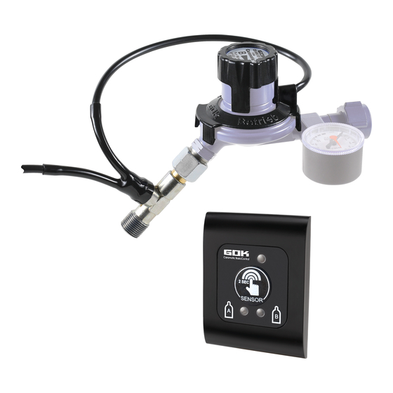
Seite 4: Aufbau
Caramatic BasicControl AUFBAU Zweiflaschenanlage Caramatic BasicTwo mit Caramatic BasicControl Anwendungsbeispiel Umschaltregler T-Stück mit Verbindungskabel zwischen Signalgeber für Fernanzeige Druck- und Reedsensor 2-teilig (Ring und Kappe) Anschlusskabel Geber für Fernanzeige Gasflasche des Zentralreglers Informations- und Steuereinheit (Bedienpanel) Verbindungskabel für Anschlusskabel Gasflasche des Umschaltreglers... -
Seite 5: Montage
Caramatic BasicControl MONTAGE Vor der Montage ist das Produkt auf Transportschäden und Vollständigkeit zu prüfen. Montage Informations- und Steuereinheit (Bedienpanel) 1. Produkt dem Karton entnehmen und in die Einzelteile (Abdeckdose, Frontplatte mit Leiterplatte und Abdeckrahmen) zerlegen. Eine Aufputzdose ist nicht im Lieferumfang enthalten. - Seite 6 Caramatic BasicControl 8. Das Bedienpanel montieren. Dazu Frontplatte mit Abdeckdose in den Ausschnitt gerade einpassen und mit 4 Schrauben an der Wand befestigen. Abschließend Abdeckrahmen auf das Bedienpanel aufstecken. Montage des Signalgebers Nur in Verbindung mit der Zweiflaschenanlage Caramatic BasicTwo.
-
Seite 7: Elektrischer Anschluss
Caramatic BasicControl Montage an die Zweiflaschenanlage Caramatic BasicTwo • Mitteldruck-Schlauchleitung der Zweiflaschenanlage Caramatic BasicTwo mit Anschluss AG G 3/8-LH-ÜM an T-Stück montieren, Anzugsmoment 15 Nm. • Eingangsanschluss des Umschaltreglers so an das Gasflaschenventil anschließen, dass der Signalgeber oben ist. • Anschluss nur von Hand, keine Werkzeuge verwenden! (Linksgewinde!). -
Seite 8: Inbetriebnahme
Caramatic BasicControl Verbindung : 3-poliger Stecker / 3-polige Buchse Die Installationsbedingungen der EN 1648-1 oder EN 1648-2 (Installation im Caravan und Motorcaravan) bzw. der EN ISO 10133 (Installation auf Kleinen Wasserfahrzeugen) beachten. • Aderfarbe des Anschlusskabels (vom Druck- und Reedsensor) des Signalgebers für... -
Seite 9: Anzeige Bedienpanel
Caramatic BasicControl ANZEIGE BEDIENPANEL Manuelles Umschalten*: Pfeil für Entnahmerichtung im Drehknopf des Umschaltreglers manuell auf „Reserve“ stellen. Gasflaschenwechsel durchführen. DICHTHEITSKONTROLLE** durchführen: *Manuelles Umschalten: Pfeil für Entnahmerichtung im Drehknopf des Umschaltreglers manuell auf „Betrieb“ oder „Reserve“ stellen. **siehe Montage- und Bedienungsanleitung „Zweiflaschenanlage Caramatic BasicTwo“... -
Seite 10: Fehlerbehebung
Keine LED-Anzeige Fernanzeige aktivieren: siehe INBETRIEBNAHME Verkabelung überprüfen (insbesondere Stromversorgung). Weiterhin keine LED-Anzeige: Caramatic BasicControl zurück an den Hersteller senden. Obere LED-Anzeige Verkabelung überprüfen (Seite 8), Gasflaschenventile zudrehen, blinkt gelb Stromversorgung kurz unterbrechen als Neustart der Fernanzeige, Gasflaschenventile öffnen:... -
Seite 11: Instandsetzung
Elektrogeräte der Marke „GOK“ nach Nutzungsbeendigung auf eigene Kosten gemäß den Richtlinien des Elektro- und Elektronikgerätegesetzes (ElektroG) ordnungsgemäß zu entsorgen. Damit wird die GOK Regler- und Armaturen- Gesellschaft mbH & Co. KG von den Verpflichtungen nach § 10 Abs. 2 ElektroG und damit im Zusammenhang stehender Ansprüche Dritter freigestellt. -
Seite 12: Ex-Schutz Daten
ISO 50001 siehe: www.gok.de/qualitaets-umwelt-und-energiemanagementsystem. KONFORMITÄTSERKLÄRUNG Die Konformitätserklärung vom Hersteller für dieses Produkt erhalten Sie im Internet unter: www.gok.de/konformitaetserklaerungen Regler- und Armaturen-Gesellschaft mbH & Co. KG Obernbreiter Straße 2-18 • 97340 Marktbreit / Germany Tel.: +49 9332 404-0 • Fax: +49 9332 404-43 E-Mail: info@gok-online.de •...