Gemü 695 Originalbetriebsanleitung
Metall, dn 15 - 50
Vorschau ausblenden
Andere Handbücher für 695:
- Betriebsanleitung (80 Seiten) ,
- Original einbau- und montageanleitung (40 Seiten) ,
- Originalmontageanleitung (13 Seiten)

Verwandte Anleitungen für Gemü 695


Inhaltszusammenfassung für Gemü 695
- Seite 1 Membranventil Metall, DN 15 - 50 Diaphragm Valve Metal, DN 15 - 50 ORIGINALBETRIEBSANLEITUNG OPERATING INSTRUCTIONS 695_us...
-
Seite 2: Inhaltsverzeichnis
Inhaltsverzeichnis Allgemeine Hinweise Allgemeine Hinweise Voraussetzungen für einwandfreie Allgemeine Funktion des GEMÜ-Ventils: Sicherheitshinweise Sachgerechter Transport und Lagerung. Hinweise für Service- Installation und Inbetriebnahme durch und Bedienpersonal eingewiesenes Fachpersonal. Warnhinweise Bedienung gemäß dieser Verwendete Symbole Betriebsanleitung. Sicherheitshinweis am Produkt Ordnungsgemäße Instandhaltung. Begriff... -
Seite 3: Hinweise Für Service- Und Bedienpersonal
Hinweise für Service- Warnhinweise und Bedienpersonal Warnhinweise sind, soweit möglich, nach folgendem Schema gegliedert: Die Betriebsanleitung enthält grundlegende Sicherheitshinweise, die bei Inbetriebnah- SIGNALWORT me, Betrieb und Wartung zu beachten sind. Nichtbeachtung kann zur Folge haben: Art und Quelle der Gefahr ®... -
Seite 4: Sicherheitshinweis Am Produkt
Tätigkeiten. branventils. Pfeil: Beschreibt Reaktion(en) auf ® Vorgesehener Einsatzbereich Tätigkeiten. Das GEMÜ-Membranventil 695 ist für Aufzählungszeichen den Einsatz in Rohrleitungen konzipiert. Es steuert ein durchfl ießendes Medium indem es durch ein Steuermedium Sicherheitshinweis am geschlossen oder geöff net werden kann. -
Seite 5: Technische Daten
Technische Daten Betriebsmedium Aggressive, neutrale, gasförmige und fl üssige Medien, die die physikalischen und chemischen Eigenschaften des jeweiligen Gehäuse- und Membranwerkstoff es nicht negativ beeinfl ussen. Das Ventil ist in beiden Durchfl ussrichtungen bis zum vollen Betriebsdruck dicht (Druckwerte in bar-Überdruck). Temperaturen Medientemperatur -10 ... - Seite 6 Kv-Werte [m³/h] Rohrnorm EN 10357 EN 10357 DIN 11850 SMS 3008 ASME ISO 1127 / DIN ISO Serie B Serie A Reihe 3 BPE / EN 10357 (ehemals (ehemals DIN 11866 Serie C / DIN 11850 DIN 11850 Reihe C DIN 11866 Reihe 1) Reihe 2) /...
-
Seite 7: Bestelldaten
Bestelldaten Gehäuseform Code Ventilkörperwerkstoff Code Durchgang EN-GJL-250, (GG 25) EN-GJS-400-18-LT (GGG 40.3) PFA-Auskleidung EN-GJS-400-18-LT (GGG 40.3) PP-Auskleidung Anschlussart Code 1.4435, Feinguss Schweißstutzen 1.4408, Feinguss Stutzen DIN 1.4408, PFA-Auskleidung Stutzen EN 10357 Serie B 1.4435 (316L), Schmiedekörper (ehemals DIN 11850 Reihe 1) 1.4435 (BN2), Schmiedekörper Δ... - Seite 8 Innenoberfl ächengüten für Schmiede- und Vollmaterialkörper Mechanisch poliert Elektropoliert Medienberührte Hygieneklasse Hygieneklasse Innenoberfl ächen Code Code DIN 11866 DIN 11866 Ra ≤ 0,80 μm 1502 1503 Ra ≤ 0,60 μm 1507 1508 Ra ≤ 0,40 μm 1536 1537 Ra ≤ 0,25 μm 1527 1516 Mechanisch poliert...
-
Seite 9: Herstellerangaben
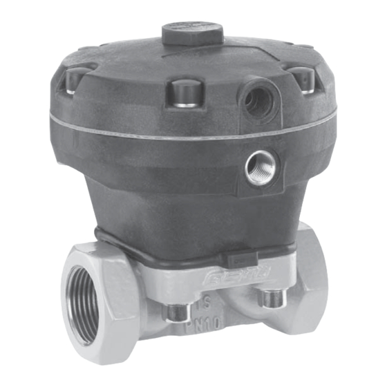
Werkzeug benutzen. Verpackungsmaterial entsprechend Funktionsbeschreibung den Entsorgungsvorschriften / Umwelt- schutzbestimmungen entsorgen. GEMÜ 695 ist ein Metall-Membranventil mit Durchgangskörper. Das Ventil besitzt einen Lieferung und Leistung wartungsarmen Membranantrieb, der mit Ware unverzüglich bei Erhalt auf neutralen Gasen angesteuert werden kann. -
Seite 10: Montage Und Bedienung
10 Montage und Bedienung VORSICHT Vor Einbau: Maximal zulässigen Druck nicht Ventilkörper- und Membranwerkstoff überschreiten! entsprechend Betriebsmedium auslegen. ® Eventuell auftretende Druckstöße Eignung vor Einbau prüfen! (Wasserschläge) durch Siehe Kapitel 5 "Technische Daten". Schutzmaßnahmen vermeiden. Montagearbeiten nur durch geschultes 10.1 Montage des Fachpersonal. -
Seite 11: Steuerfunktionen
5. Anlage bzw. Anlagenteil vollständig Montage bei Flanschanschluss: entleeren und abkühlen lassen bis 1. Auf saubere und unbeschädigte Dicht- Verdampfungstemperatur des Mediums fl ächen der Anschlussfl ansche achten. unterschritten ist und Verbrühungen 2. Flansche vor Verschrauben sorgfältig ausgeschlossen sind. ausrichten. 6. -
Seite 12: Steuerfunktion
Steuerfunktion 3 Steuerfunktion Anschluss Beidseitig angesteuert (DA): Federkraft geschlossen 2: Steuermedium Ruhezustand des Ventils: keine defi nierte (NC) (Öff nen) Grundposition. Öff nen und Schließen des Federkraft geöff net 4: Steuermedium Ventils durch ansteuern der entsprechenden (NO) (Schließen) Steuermediumanschlüsse (Anschluss 2: Öff - 2: Steuermedium nen / Anschluss 4: Schließen). -
Seite 13: Demontage Membrane
11.2 Demontage Membrane Wichtig: Ist die Membrane nicht weit genug Wichtig: in das Verbindungsstück einge- Vor Demontage der Membrane schraubt, wirkt die Schließkraft bitte Antrieb demontieren, siehe direkt auf den Schraubpin und nicht "Demontage Ventil (Antrieb vom über das Druckstück. Das führt zu Körper lösen)". - Seite 14 11.3.3 Montage der Konvex-Membrane 1. Antrieb A in Geschlossen-Position bringen. 2. Scheibe lose auf Ventilspindel aufsetzen. Druckstück lose auf Scheibe aufsetzen, Nasen in Führungen einpassen (siehe Kapitel 11.3.1 "Allgemeines"). 3. Kontrollieren ob das Druckstück in den Führungen liegt. 4. Neues Membranschild von Hand umklap- Druckstück lose auf Scheibe aufsetzen, pen;...
-
Seite 15: Montage Antrieb Auf Ventilkörper
10. Membranschild von Hand fest auf die VORSICHT Stützmembrane drücken, so dass sie Gegen Leckage vorbeugen! zurückklappt und an der Stützmembrane Schutzmaßnahmen gegen Überschrei- anliegt. tung des maximal zulässigen Drucks durch eventuelle Druckstöße (Wasser- 11.4 Montage Antrieb schläge) vorsehen. auf Ventilkörper Vor Reinigung bzw. -
Seite 16: Demontage
15.1 Demontage zur Entsorgung 1. Geeignete Schutzausrüstung gemäß für Steuerfunktion 1 den Regelungen des Anlagenbetreibers berücksichtigen. 2. Anlage bzw. Anlagenteil stilllegen. 3. Gegen Wiedereinschalten sichern. 4. Anlage bzw. Anlagenteil drucklos schalten. Der Betreiber muss regelmäßige Sichtkon- trollen der Ventile entsprechend den Einsatz- bedingungen und des Gefährdungspoten- zials zur Vorbeugung von Undichtheit und Beschädigungen durchführen. -
Seite 17: Rücksendung
WARNUNG Hinweis zur Rücksendung: Aufgrund gesetzlicher Antriebsoberteil 10 steht Bestimmungen zum Schutz unter Federdruck! der Umwelt und des Personals ® Gefahr von schwersten ist es erforderlich, dass Sie die Verletzungen oder Tod! Erklärung (anbei) vollständig Antrieb nur unter Presse ausgefüllt und unterschrieben öff... -
Seite 18: Fehlersuche / Störungsbehebung
18 Fehlersuche / Störungsbehebung Fehler Möglicher Grund Fehlerbehebung Steuermedium entweicht aus Entlüftungsbohrung* im Oberteil des Antriebs bei Steuerfunktion Steuermembrane defekt Antrieb austauschen 1 (NC) bzw. Anschluss 2* bei Steuerfunktion 2 (NO) Steuermedium entweicht aus Leckagebohrung* (nur bei Antrieb austauschen und Steuermedium Spindelabdichtung undicht Steuerfunktion 1 (NC) und auf Verschmutzungen untersuchen... -
Seite 19: Schnittbild Und Ersatzteile
19 Schnittbild und Ersatzteile Entlüftungs- bohrung Steuer- membrane Anschluss Leckagebohrung Pos. Benennung Bestellbezeichnung Ventilkörper K600... Membrane 600...M Schraube 695...S30... Scheibe Antrieb 9695... 695_us 19 / 44... -
Seite 20: Eg-Konformitätserklärung
GEMÜ Gebr. Müller GmbH & Co. KG Fritz-Müller-Straße 6-8 D-74653 Ingelfi ngen erklären, dass unten aufgeführte Armaturen die Sicherheitsanforderungen der Druckgeräte- richtlinie 97/23/EG erfüllen. Benennung der Armaturen - Typenbezeichnung Membranventil GEMÜ 695 Benannte Stelle: TÜV Rheinland Berlin Brandenburg Nummer: 0035 Zertifi kat-Nr.: 01 202 926/Q-02 0036 Konformitätsbewertungsverfahren:... - Seite 43 695_us 43 / 44...
- Seite 44 VENTIL-, MESS- UND REGELSYSTEME VALVES, MEASUREMENT AND CONTROL SYSTEMS GEMÜ Gebr. Müller Apparatebau GmbH & Co. KG · Fritz-Müller-Str. 6-8 · D-74653 Ingelfi ngen-Criesbach Telefon +49(0)7940/123-0 · Telefax +49(0)7940/123-192 · info@gemue.de · www.gemue.de...