Gemü 673 Original Einbau- Und Montageanleitung
Vorschau ausblenden
Andere Handbücher für 673:
- Original einbau- und montageanleitung (44 Seiten) ,
- Original einbau- und montageanleitung (40 Seiten) ,
- Original einbau- und montageanleitung (40 Seiten)

Verwandte Anleitungen für Gemü 673


Inhaltszusammenfassung für Gemü 673
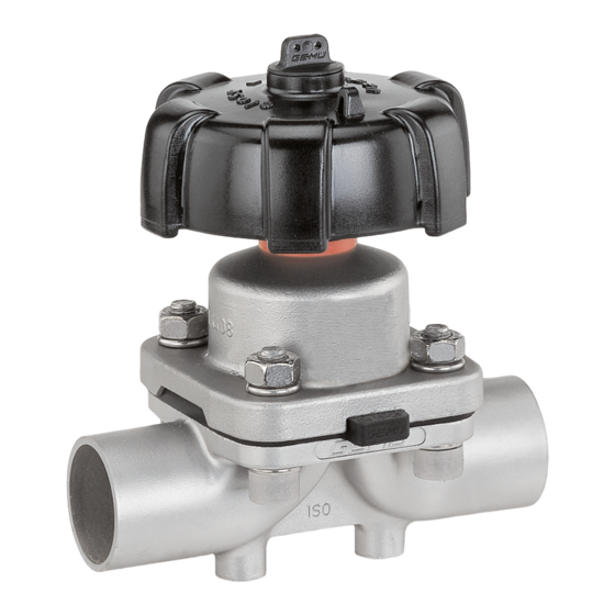
- Seite 1 Membranventil Metall, DN 15 - 50 Diaphragm Valve Metal, DN 15 - 50 ORIGINAL EINBAU- UND MONTAGEANLEITUNG INSTALLATION, OPERATING AND MAINTENANCE INSTRUCTIONS...
-
Seite 2: Inhaltsverzeichnis
Inhaltsverzeichnis Allgemeine Hinweise Voraussetzungen für die einwandfreie Allgemeine Hinweise Funktion des GEMÜ-Ventils: Allgemeine Sicherheitshinweise 2 Sachgerechter Transport und Lagerung Hinweise für Service- Installation und Inbetriebnahme durch und Bedienpersonal eingewiesenes Fachpersonal Warnhinweise Bedienung gemäß dieser Einbau- und Technische Daten Montageanleitung Verwendete Symbole Ordnungsgemäße Instandhaltung Begriff... -
Seite 3: Hinweise Für Service
Hinweise für Service- Warnhinweise und Bedienpersonal Warnhinweise sind, soweit möglich, nach folgendem Schema gegliedert: Die Einbau- und Montageanleitung enthält grundlegende Sicherheitshinweise, die bei SIGNALWORT Inbetriebnahme, Betrieb und Wartung zu beachten sind. Nichtbeachtung kann zur Art und Quelle der Gefahr Folge haben: ®... -
Seite 4: Technische Daten
Verwendete Symbole Vorgesehener Einsatzbereich Das GEMÜ-Membranventil 673 ist für Gefahr durch heiße Oberfl ächen! den Einsatz in Rohrleitungen konzipiert. Es steuert ein durchfl ießendes Medium durch Handbetätigung. Gefahr durch ätzende Stoff e! Das Ventil darf nur gemäß den technischen Daten eingesetzt werden Quetschgefahr! (siehe Kapitel 5 "Technische Daten"). - Seite 5 Temperaturen Medientemperatur FKM (Code 4/4A) -10 ... 90 °C EPDM (Code 13/3A) -10 ... 100 °C EPDM (Code 17) -10 ... 100 °C EPDM (Code 19) -10 ... 100 °C EPDM (Code 36) -10 ... 100 °C PTFE/EPDM (Code 54) -10 ...
-
Seite 6: Bestelldaten
Bestelldaten Ventiltyp Code Ventilkörperwerkstoff Code GEMÜ 673 Membrangröße 25 - 50 EN-GJS-400-18-LT (GGG 40.3) PFA-Auskleidung EN-GJS-400-18-LT (GGG 40.3) PP-Auskleidung 1.4435, Feinguss Gehäuseform Code 1.4408, Feinguss Behälterkörper 1.4435 (316L), Schmiedekörper Durchgang 1.4435 (BN2), Schmiedekörper Δ Fe<0,5% T-Körper 1.4539, Schmiedekörper * Abmessungen siehe Broschüre T-Ventile ** Abmessungen und Ausführungen auf Anfrage... - Seite 7 Innenoberflächengüten für Schmiede- und Vollmaterialkörper Mechanisch poliert Elektropoliert Medienberührte Hygieneklasse Hygieneklasse Innenoberflächen Code Code DIN 11866 DIN 11866 Ra ≤ 0,80 μm 1502 1503 Ra ≤ 0,60 μm 1507 1508 Ra ≤ 0,40 μm 1536 1537 Ra ≤ 0,25 μm 1527 1516 Mechanisch poliert...
-
Seite 8: Herstellerangaben
Werkzeug benutzen. Artikelnummer Seriennummer Funktionsbeschreibung Der Herstellungsmonat ist unter der Rückmeldenummer verschlüsselt und kann GEMÜ 673 ist ein Metall-Membranventil bei GEMÜ erfragt werden. mit Durchgangs-, T- oder Behälterboden- Das Produkt wurde in Deutschland Ablasskörper bzw. Ausführung in hergestellt. Mehrwegeausführung. Antriebsgehäuse und -mechanik sind komplett aus Edelstahl. -
Seite 9: Montage Und Bedienung
10 Montage und Bedienung VORSICHT Vor Einbau: Ventil äußerlich nicht stark beanspruchen. Ventilkörper- und Membranwerkstoff Installationsort so wählen, dass Ventil entsprechend Betriebsmedium auslegen. nicht als Steighilfe genutzt werden kann. Eignung vor Einbau prüfen! Rohrleitung so legen, dass Schub- und Siehe Kapitel 5 "Technische Daten". Biegungskräfte, sowie Vibrationen und Spannungen vom Ventilkörper 10.1 Montage des... -
Seite 10: Bedienung
Montage bei Clampanschluss: Entsprechende Vorschriften für Bei Montage der Clampanschlüsse Anschlüsse beachten! entsprechende Dichtung zwischen Ventilkörper und Rohranschluss einlegen Nach der Montage: und mit Klammer verbinden. Die Dichtung Alle Sicherheits- und Schutzeinrichtungen sowie die Klammer der Clampanschlüsse wieder anbringen bzw. in Funktion setzen. sind nicht im Lieferumfang enthalten. -
Seite 11: Einstellung Der Schließbegrenzung
Einstellung der Schließbegrenzung nur bei komplett montiertem Ventil (mit Membrane und Ventilkörper) und in kaltem Zustand! Zum Schutz der Dichtmembrane verfügen die Ventile der Baureihe GEMÜ 673 serienmäßig über eine mechanisch einstellbare Schließbegrenzung. 5. Gewindespindel entsprechend den Standardeinstellung: Einsatzbedingungen nachfetten,... -
Seite 12: Montage / Demontage Von Ersatzteilen
11.1 Demontage Ventil aufsetzen (Fase unten) und soweit (Antrieb vom Körper lösen) aufschrauben bis er auf dem Ventilantrieb anliegt. 1. Antrieb A in Off en-Position bringen. 2. Antrieb A vom Ventilkörper 1 demontieren. 3. Antrieb A in Geschlossen-Position bringen. Wichtig: Nach Demontage alle Teile von Verschmutzungen reinigen (Teile dabei nicht beschädigen). -
Seite 13: Montage Membrane
11.3 Montage Membrane Druckstück und Antriebsflansch von unten gesehen: 11.3.1 Allgemeines Wichtig: Für Ventil passende Membrane einbauen (geeignet für Medium, Mediumkonzentration, Temperatur und Druck). Die Absperrmembrane ist ein Verschleißteil. Vor Inbetriebnahme und über gesamte Einsatzdauer des Membranventils technischen Zustand und Funktion überprüfen. -
Seite 14: Montage Der
11.3.3 Montage der 11.4 Montage Antrieb Konvex-Membrane auf Ventilkörper 1. Antrieb A in Geschlossen-Position 1. Antrieb A in Geschlossen-Position bringen. bringen. 2. Neuen Membranschild von Hand 2. Antrieb A ca. 20 % öff nen. umklappen; bei großen Nennweiten 3. Alle Teile von Produktresten und saubere, gepolsterte Unterlage Verschmutzungen reinigen. -
Seite 15: Inbetriebnahme
12 Inbetriebnahme 13 Inspektion und Wartung WARNUNG WARNUNG Aggressive Chemikalien! Unter Druck stehende Armaturen! ® Verätzungen! ® Gefahr von schwersten Verletzungen Vor Inbetriebnahme Dichtheit oder Tod! der Medienanschlüsse Nur an druckloser Anlage arbeiten. prüfen! Dichtheitsprüfung VORSICHT nur mit geeigneter Heiße Anlagenteile! Schutzausrüstung. -
Seite 16: Demontage
16 Rücksendung Wichtig: Wartung und Service: Membranventil reinigen. Gewindespindel entsprechend den Rücksendeerklärung bei GEMÜ Einsatzbedingungen nachfetten, anfordern. besonders wenn das Ventil Rücksendung nur mit vollständig autoklaviert wird. ausgefüllter Rücksendeerklärung. Siehe Kapitel 10.3, Punkt 5. Ansonsten erfolgt keine Gutschrift bzw. keine Erledigung der Reparatur 14 Demontage sondern eine kostenpflichtige Entsorgung. -
Seite 17: Fehlersuche / Störungsbehebung
18 Fehlersuche / Störungsbehebung Fehler Möglicher Grund Fehlerbehebung Medium entweicht aus Absperrmembrane auf Beschädigungen Absperrmembrane defekt Leckagebohrung* prüfen, ggf. Membrane tauschen Antrieb defekt Antrieb austauschen Ventil öffnet nicht bzw. nicht Absperrmembrane nicht korrekt Antrieb demontieren, Membranmontage vollständig montiert prüfen, ggf. austauschen Ventil mit Betriebsdruck laut Datenblatt Betriebsdruck zu hoch betreiben... -
Seite 18: Schnittbild Und Ersatzteile
19 Schnittbild und Ersatzteile Leckagebohrung Pos. Benennung Bestellbezeichnung Ventilkörper K600... Membrane 600...M Schraube Scheibe 673...S30... Mutter Antrieb 9673... Einstellring Arretierungsschraube 673 ..SHK 0.T. AGO. O-Ring Handrad 18 / 40... -
Seite 19: Ersatzteil-Set "Handrad Komplett
Gewinde Tr16x2 haben. Entsprechend dem Gewinde (Pfeil) des Antriebsoberteils A* die passende Version aufschrauben. Bestelldaten Einstellring Pos. Benennung Bestellbezeichnung 673 25SHK 02TS AGO4 Einstellring 673 25SHK 02TW AGOF (Gewinde 673 40SHK 03TS AGOD M16x1,5) 673 50SHK 04TS AGOE Pos. Benennung... -
Seite 20: Eu-Konformitätserklärung
GEMÜ Gebr. Müller Apparatebau GmbH & Co. KG Fritz-Müller-Straße 6-8 D-74653 Ingelfingen erklären, dass unten aufgeführte Armaturen die Sicherheitsanforderungen der Druckgeräte- richtlinie 2014/68/EU erfüllen. Benennung der Armaturen - Typenbezeichnung Membranventil GEMÜ 673 Benannte Stelle: TÜV Rheinland Industrie Service GmbH Nummer: 0035 Zertifikat-Nr.: 01 202 926/Q-02 0036... - Seite 39 39 / 40...
- Seite 40 GEMÜ Gebr. Müller Apparatebau GmbH & Co. KG · Fritz-Müller-Str. 6-8 · D-74653 Ingelfi ngen-Criesbach Telefon +49(0)7940/123-0 · Telefax +49(0)7940/123-192 · info@gemue.de · www.gemu-group.com...