Herunterladen Inhalt Inhalt Diese Seite drucken
SPORTSTECH HGX200 Benutzerhandbuch

SPORTSTECH HGX200 Benutzerhandbuch

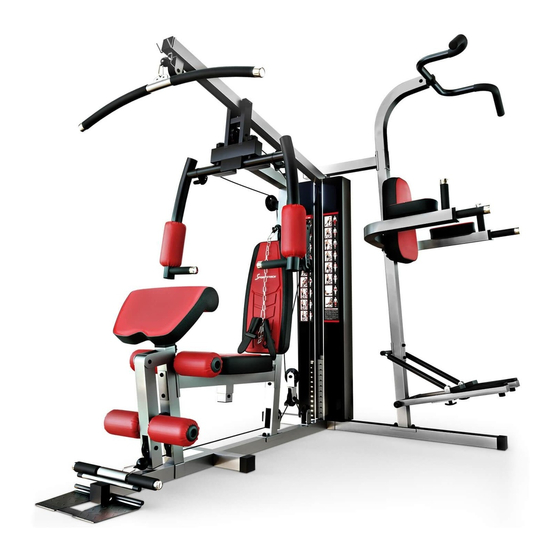
Two station home gym
Vorschau ausblenden Andere Handbücher für HGX200:

Werbung

Verfügbare Sprachen
  • DE

Verfügbare Sprachen

  • DEUTSCH, seite 1
HGX200
Two Station Home Gym
DE
EN
ES
FR
IT

Werbung

Inhaltsverzeichnis
loading

Inhaltszusammenfassung für SPORTSTECH HGX200

  • Seite 1 HGX200 Two Station Home Gym...
  • Seite 2 BENUTZERHANDBUCH DEUTSCH...
  • Seite 3: Video Tutorials

    Video Tutorials Unsere für dich! Aufbau Benutzung Abbau In 3 einfachen Schritten zum schnellen und sicheren Start: 1. QR-Code scannen 2. Videos anschauen 3. schnell und sicher starten Link zu den Videos: https://sportstech.de/qr/hgx200.html...
  • Seite 4 Sehr geehrter Kunde wir freuen uns, dass Sie sich für ein Gerät aus der SPORTSTECH Produktpalette entschieden haben. SPORTSTECH Sportgeräte bieten Ihnen höchste Qualität und neueste Technologie. Um die Leistungsfähigkeit des Gerätes voll nutzen zu können und viele Jahre Freude an Ihrem Gerät zu haben, lesen Sie bitte vor der Inbetriebnahme und dem Beginn des Trainings dieses Benutzerhandbuch sorgfältig durch und verwenden Sie das Gerät den Anweisungen entsprechend.
  • Seite 5: Inhaltsverzeichnis

    INHALT Sicherheitshinweise Technische Daten Teile-Liste Hardwarepaket Komponenten Aufbauanleitung Trainings-Informationen Reinigung und Pflege MONTAGE- UND BEDIENUNGSANLEITUNG - BITTE ZUM SPÄTEREN NACHLESEN AUFBEWAHREN WICHTIG - BITTE LESEN SIE DIESE ANWEISUNGEN VOLLSTÄNDIG, BEVOR SIE MIT DER MONTAGE ODER BENUTZUNG BEGINNEN Diese Anleitung enthält wichtige Informationen, die Ihnen helfen, von Ihrer Ausrüstung optimalen Gebrauch zu machen und eine sichere und korrekte Montage, Benutzung und Wartung sicherzustellen.
  • Seite 6: Sicherheitshinweise

    SICHERHEITSHINWEISE WICHTIG - BITTE VOLLSTÄNDIG DURCHLESEN, BEVOR SIE MIT DER MONTAGE ODER BENUTZUNG BEGINNEN Um das Risiko schwerer Verletzungen zu verringern, lesen Sie die gesamte Anleitung, bevor Sie Ihr Gerät zusammenbauen oder benutzen. Beachten Sie insbesondere die folgenden Vorsichtsmaßnahmen. MONTAGE •...
  • Seite 7: Technische Daten

    Bitte beachten Sie, dass es bei diesem Produkt eine Gewichtstoleranz von ca. 4% geben kann. TECHNISCHE DATEN • Das Nettogewicht des Modells beträgt: 155,1 kg • Die Baugröße beträgt: 2116 x 1756 x 2196 mm • Max. Benutzergewicht: 120 kg Das HGX200 ist nach EN ISO 20957-1:2013 & EN 957-2:2003 & EN 957-8:1998 zertifiziert.
  • Seite 8: Teile-Liste

    TEILE-LISTE Teil Beschreibung Anzahl Teil Beschreibung Anzahl Oberer Rahmen Schaumstoffrolle für Seitenausleger Vorderer vertikaler Rahmen Kabel für Seitenausleger Grundrahmen Oberes Kabel Rückwärtiger Stabilisator Unteres Kabel Beinzug-Halter L=15 Buchse Sitzpolster-Träger L=13 Buchse Sitzpolster-Verstellrahmen Kabelbefestigung Beinzug Kabelhülse Frontunterrahmen Fußgelenkgurt Rechter Seitenausleger T-förmiger Verriegelungsstift Linker Seitenausleger Haken Handgriff...
  • Seite 9: Beschreibung

    Teil Beschreibung Anzahl Teil Beschreibung Anzahl Verkleidung für Gewichte-Stapel Linker Pedalrahmen Gummipuffer Hydrozylinder Gummipuffer Kraft-Turm Rückenpolster Ø24,5xØ31x460 Handgriff Kraft-Turm Armcurl Polster Ø24,5xØ31x120 Handgriff Halterung Ø24xØ31x150 Handgriff U-förmige Halterung Rutschfest Verbindungsrahmen Bauchgurt U-förmige Halterung Einzelner Gurt L-förmiger Stift Sicherungsstift Pedal Endkappe Gummipuffer M10×30 Inbusschraube Endkappe...
  • Seite 10: Hardwarepaket

    HARDWAREPAKET...
  • Seite 11: Komponenten

    KOMPONENTEN...
  • Seite 17: Aufbauanleitung

    AUFBAUANLEITUNG SCHRITT 1 Führen Sie die 2-teilige Führungsstange (18#) in die Bohrungen des hinteren Stabilisators (4#) ein. Richten Sie die Löcher sorgfältig aus und befestigen Sie die Teile mit 2 M10×25mm Inbusschrauben (96#) und 2 Ø10- Unterlegscheiben (105#).
  • Seite 18 SCHRITT 2 Befestigen Sie den Hauptträgerrahmen (3#) am hinteren Stabilisator (4#). Richten Sie die Löcher sorgfältig aus und befestigen Sie mit 2 M10×70mm Schlossschrauben (91#), 1 Halterung (13#), 2 Ø10-Unterlegscheiben (105#) und 2 M10-Schraubenmuttern (103#).
  • Seite 19 SCHRITT 3 Setzen Sie den vorderen vertikalen Rahmen (2#) auf den Hauptträgerrahmen (3#) und sichern Sie mit 2 M10x70 Schlossschrauben (91#), 1 Halterung (21#), 2 Ø10-Unterlegscheiben (105#) und 2 M10-Schraubenmuttern (103#).
  • Seite 20 SCHRITT 4 Schieben Sie zwei Gummipuffer (54#) entlang der Führungsstangen (18#) nach unten. Und dann platzieren Sie 11 Stück 5-Kg Gewichtsplatten (34#) entlang der Führungsstangen, und stellen Sie dabei sicher, dass die Mutter jeweils nach vorne und nach unten weist. Führen Sie die Wählstange (20#) in das Mittelloch ein und platzieren Sie die kleine 2,5-Kg Gewichtsplatte (35#) auf die anderen Gewichtsplatten.
  • Seite 21 SCHRITT 5 A. Befestigen Sie den oberen Rahmen (1#) am vorderen vertikalen Rahmen (2#) und zwei Führungsstangen (18#). B. Befestigen Sie den vorderen vertikalen Rahmen (2#) mittels 2 M10x70mm Schlossschrauben (91#), 1 Halterung (21#), 2 Ø10mm-Unterlegscheiben (105#) und 2 M10 Schraubenmuttern (103#). C.
  • Seite 22 SCHRITT 6 A. Bringen Sie den unteren Rahmen (111#) am hinteren Stabilisator (4#) an und sichern Sie zusammen mit 2 M10×70mm Schlossschrauben (91#), 1 Halterung (21#), 2 Ø10-Unterlegscheiben (105#) und 2 M10 Schraubenmuttern (103#). B. Setzen Sie den oberen Rahmen (112#) in den unteren Rahmen (111#) und sichern Sie zusammen mit 2 10×70mm Schlossschrauben (91#), 2 Halterungen (144#), 2 Ø10-Unterlegscheiben (105#) und 2 M10 Schraubenmuttern (103#).
  • Seite 23 SCHRITT 7 Befestigen Sie die Sitzpolsterstütze (6#) am vorderen vertikalen Rahmen (2#) und befestigen diese mit 2 M10×70mm Schlossschrauben (91#), 1 Halterung (21#), 2 Ø10-Unterlegscheiben (105#) und 2 M10-Schraubenmuttern (103#). Befestigen Sie den Beinzughalter (5#) wie in der Abbildung gezeigt. Sichern Sie ihn mit dem Hauptträgerrahmen und der Sitzpolsterstütze (6#) mittels 3 M10x70mm Schlossschrauben (91#), 1 Halterung (21#), 3 Ø10-Unterlegscheiben (105#) und 3 M10-Schraubenmuttern (103#).
  • Seite 24 SCHRITT 8 Setzen Sie die vordere Grundplatte (9#) am oberen Rahmen (1#) an und befestigen Sie zusammen mit 2 M10- Schraubenmuttern (103#), 2 großen Unterlegscheiben (107#), 1 Achse (109#).
  • Seite 25 SCHRITT 9 Bringen Sie die rechte Seitenausleger-Einstellung (25#) durch das Loch der vorderen Grundplatte an und befestigen Sie mit 1 Abstandhalter (71#), Abdeckung (53#), 1 M6-Schraubenmutter (104#) und 1 M6x33mm Inbusschraube (142#). Befestigen Sie den rechten Seitenausleger (10#) an der rechten Seitenausleger-Einstellung (25#) und sichern Sie zusammen mittels 1 M8×23 Inbusschraube (90#), 2 Kunststoff-Unterlegscheiben (73#) und 1 M8×70 Inbusschraube (108#).
  • Seite 26 SCHRITT 10 Befestigen Sie das Armcurl-Pad (33#) an der Armcurl-Pad-Halterung (14#) und befestigen Sie es mit 2 M8×16mm Inbusschrauben (97#) und 2 Ø8-Unterlegscheiben (106#).Setzen Sie den Armcurl-Pad-Halter in die Öffnung des Beinzughalters ein und wählen Sie die gewünschte Höhe mit dem Knopf (51#). Bringen Sie den Beinzug (8#) am Beinzughalter (5#) an und befestigen beide mit 1 M10x80mm Inbusschraube (98#), 2 Ø10-Unterlegscheiben (105#) und 2 Buchsen (56#) sowie 1 M10-Schraubenmutter (103#).
  • Seite 27 SCHRITT 11 Befestigen Sie das Sitzpolster (31#) auf dem Sitzpolster-Einstellrahmen (7#) und sichern Sie mit 4 M8×16mm Inbusschrauben (97#) und 4 Ø8-Unterlegscheiben (106#). Führen Sie den Sitzpolster-Einstellrahmen (7#) in die Bohrung ein und wählen Sie die gewünschte Höhe mit dem Verriegelungsknopf (85#). Befestigen Sie die Rückenpolsterstütze (27#) mittes M10x110 Inbusschraube (101#) und Ø10-Unterlegscheibe (105#) am vorderen vertikalen Rahmen.
  • Seite 28 SCHRITT 12 Befestigen Sie das Schaumstoffrohr (22#) in den Löchern, so wie im Diagramm gezeigt, und befestigen Sie 4 Schaumstoffrollen (36#) und Endkappen (86#) an beiden Enden. Sichern Sie die Fußplatte (29#) mit dem Fußplattenrohr (28#) und befestigen Sie dann Endkappen (50#) an beiden Enden.
  • Seite 29 SCHRITT 13 Setzen Sie den linken und rechten Arm (114# bzw. 115#) am unteren Rahmen an, wie in der Abbildung gezeigt, und sichern Sie sie mit 4 M8×10mm Inbusschrauben (133#), 4 Ø8-Unterlegscheiben (106#), 1 Halterung (122#). Befestigen Sie den linken und rechten Arm (114# bzw. 115#) zusammen mit 1 M12×75 mm Inbusschraube (#134), 2 Ø12-Unterlegscheiben (139#), 1 M12 Schraubenmutter (#135).
  • Seite 30 SCHRITT 14 Befestigen Sie das Rückenpolster (120#) wie in der Abbildung gezeigt mit 2 M8×70mm Inbusschrauben (137#) und 2 Ø8-Unterlegscheiben (106#). Befestigen Sie die beiden Armpolster (121#) wie in der Abbildung dargestellt und sichern diese mit 4 M8×60 mm Inbusschrauben (136#) und 4 Ø8-Unterlegscheiben (106#).
  • Seite 31 SCHRITT 15...
  • Seite 32 A. Bringen Sie das 3890 mm lange obere Kabel (39#) durch die Öffnung des oberen Rahmens. Stellen Sie sicher, dass sich der Kugelanschlag vor dem oberen Rahmen befindet. Platzieren Sie 1 Seilrolle (74#) unterhalb des Kabels und sichern diese mittels 1 M10×45 Inbusschraube (94#), 2 ø10-Unterlegscheiben (105#) und 1 M10-Schraubenmutter (103#).
  • Seite 33 SCHRITT 16 A. Befestigen Sie das Ende des 3070 mm langen Schmetterlingsdrähte (38#) am Haken. B. Befestigen Sie die 2-teilige Seilrollenhalterung (15#), wie in der Abbildung gezeigt, und sichern Sie mit 1 M10×65mm Inbusschraube (#93), 2 Ø10-Unterlegscheiben (105#) und 1 M10-Schraubenmutter (103#). C.
  • Seite 34 SCHRITT 17...
  • Seite 35 A. Bringen Sie das Ende des 3890MM langen unteren Kabels (136#) durch die Bohrung des Beinzuges und platzieren Sie 1 Seilrolle an dem Kabel. Sichern Sie es mit 1 M10x60 mm Inbusschraube (102#), 2 Buchsen (42#) und 1 M10- Schraubenmutter (103#). B.
  • Seite 36 SCHRITT 18 Befestigen Sie die 2-teilige Abdeckung für die Gewichte (17#) wie in der Abbildung dargestellt, und sichern diese mit 8 M10x20 Inbusschrauben (92#), 8 Ø10 -Unterlegscheiben (105#) und 2 Klammern (141#).
  • Seite 37 SCHRITT 19 Befestigen Sie die Hydrozylinderhalterung (123#) am unteren Rahmen (111#) und sichern Sie mit 2 M10x70mm Schlossschrauben (91#), 4 Ø10-Unterlegscheiben (105#), 1 Halterung (147#) und 2 M10-Schraubenmuttern (103#). Befestigen Sie den linken und rechten Pedalrahmen (118# bzw. 117#) an der Achse des unteren Rahmens (111#) und sichern Sie diese mit 2 M8×16mm Inbusschrauben (97#) und 2 Ø8-Unterlegcheiben (145#).
  • Seite 38 SCHRITT 20 Befestigen Sie die Latzugstange (19#) am Ende des oberen Kabels mit 2 Haken (47#) und 15-gliedriger Kette (49#). Befestigen Sie den Bauchgurt (83#) an der Schließe (58#) und sichern Sie zusammen mit 1 M10x30mm Inbusschraube (87#), 2 Ø10-Unterlegscheiben (105#) und 1 M10-Schraubenmutter (103#).
  • Seite 39: Trainings-Informationen

    TRAININGS-INFORMATIONEN BEVOR SIE BEGINNEN Vor Trainingsbeginn sollten Sie Ihre körperliche Verfassung berücksichtigen. Wenn Sie längere Zeit sportlich inaktiv waren, sollten Sie mit kleineren Trainingseinheiten starten. Ihre aerobe Fitness sollte sich jedenfalls innerhalb der nächsten sechs bis acht Wochen verbessern. Und seien Sie bitte nicht entmutigt, falls es etwas länger dauert.
  • Seite 40: Aerobes Training

    Um Ihre Herzfrequenz zu messen, hören Sie auf zu trainieren, bewegen Sie jedoch weiter Ihre Beine oder gehen Sie etwas umher und legen Sie zwei Finger auf die Innenseite Ihres Handgelenks. Erfassen Sie Ihre Herzschlagzahl über sechs Sekunden hinweg und multiplizieren Sie das Ergebnis mit 10, um Ihre Herzfrequenz zu bestimmen. Zum Beispiel, wenn Ihre Herzschlagzahl innerhalb des Sechs-Sekunden-Zeitraums 14 beträgt, ist Ihre Herzfrequenz 140 Schläge pro Minute.
  • Seite 41 DEHNUNGSÜBUNGEN Bevor Sie das Laufband benutzen, ist es am besten, 5 bis 10 Minuten zum Aufwärmen Stretching-Übungen durchzuführen. Dehnen vor dem Training wird hilft die Flexibilität zu verbessern und das Verletzungsrisiko zu mindern. QUADRIZEPS-DEHNUNG Mit einer Hand an der Wand abstützen, um das Gleichgewicht besser zu halten, nach hinten greifen und den rechten Fuß...
  • Seite 42: Reinigung Und Pflege

    REINIGUNG UND PFLEGE 1. Die Sicherheit des Gerätes kann nur aufrechterhalten werden, wenn es regelmäßig auf Verschleiß und/oder Abnutzung geprüft wird, z. B. an den Verbindungspunkten. 2. Schmieren Sie bewegliche Teile regelmäßig mit Schmieröl ab, um vorzeitigem Verschleiß vorzubeugen. 3. Überprüfen Sie alle Teile vor der Benutzung des Geräts und ziehen Sie sie ggf. fest, ersetzen Sie etwa defekte Teile sofort und verwenden Sie das Gerät solange nicht mehr, bis es wieder in einwandfreiem Zustand ist.
  • Seite 44 USER MANUAL ENGLISH...
  • Seite 45 3 simple steps for a fast and safe start: 1. scan the QR code 2. watch videos 3. start fast and safely Link to the videos: https://sportstech.de/qr/hgx200.html...
  • Seite 46 Dear customer, We are pleased you chose a device from the SPORTSTECH product range. With sports equipment from SPORTSTECH you get the highest quality and latest technology. In order to fully use the potential of your device and be able to enjoy it for many years, please read this manual carefully before starting up and beginning of training, and use the device according to the instruc- tions.
  • Seite 47 INDEX Safety Information Technical specifications Spare parts list Hardware pack Components Assembly instructions Exercising Information Care and Maintenance ASSEMBLY & USER INSTRUCTIONS - PLEASE KEEP FOR FUTURE REFERENCE IMPORTANT – PLEASE READ THESE INSTRUCTIONS FULLY BEFORE ASSEMBLY OR USE This instruction contain important information which will help you get the best from your equipment and ensure safe and correct assembly, use and maintenance.
  • Seite 48: Safety Information

    SAFETY INFORMATION IMPORTANT – PLEASE READ FULLY BEFORE ASSEMBLY OR USE To reduce the risk of serious injury, read the entire manual before you assemble or use your bench. In particular, note the following safety precautions. ASSEMBLY • Check you have all the components and tools listed in the parts list, bearing in mind that, for ease of assembly, some components are pre-assembled.
  • Seite 49: Technical Specifications

    The Netto weight of the model is: 155,1 kg • The assembly size is: 2116 x 1756 x 2196 mm • Max. user weight: 120 kg The HGX200 is certified to EN ISO 20957-1:2013 & EN 957-2:2003 & EN 957-8:1998.
  • Seite 50: Spare Parts List

    SPARE PARTS LIST Part Description Qty. Part Description Qty. Upper frame Lower cable Front vertical frame L=15 bushing Main base frame L=13 bushing Rear stabiliser cable retainer leg developer holder bushing Seat pad support Ankle strap seat pad adjustment frame T shape Lock pin Leg developer Gourd hook...
  • Seite 51 Part Description Qty. Part Description Qty. Ø24.5*Ø31*460 handle grip power tower arm curl pad Ø24.5*Ø31*120 handle grip bracket Ø24*Ø31*150 handle grip U shape bracket Anti slip Connection frame Abdominal strap U shape bracket Single strap L shape pin lock pin Pedal End cap Rubber bumper...
  • Seite 52: Hardware Pack

    HARDWARE PACK...
  • Seite 53 COMPONENTS...
  • Seite 59 ASSEMBLY INSTRUCTIONS STEP 1 Insert the 2pcs guide rod(18#) into the holes of the rear stabiliser(4#), Carefully align the holes and secure them with 2pcs M10×25mm Allen bolt (96#), 2pcs Ø10 washer(105#).
  • Seite 60 STEP 2 Attach the main base frame(3#) to the rear stabiliser(4#), Carefully align the holes and secure them with 2pcs M10×70mm Carriage bolt (91#),1 pc bracket (13#),2pcs Ø10 washer(105#) and 2pcs M10 Aircraft nut (103#).
  • Seite 61 STEP 3 Place the front vertical frame(2#) onto the main base frame (3#) and secure them with 2pcsM10*70 Carriage bolt(91#),1pc bracket(21#),2pcs Ø10 washer (105#) and 2pcs M10 Aircraft nut (103#).
  • Seite 62 STEP 4 Slide two rubber bumper (54#) down along the guide rods (18#). And then place 11 pcs 5-kg weight plate(34#) along the guide rods ,Make sure all the groove face front and downwards.Insert the selector rod(20#) into the center hole and place the small 2.5-Kg weight plate (35 #) above the other weight plates.
  • Seite 63 STEP 5 A.) Attach the upper frame (1#) onto the front vertical frame(2#) and two Guide rods (18#). B.) Fix to front vertical frame(2#) using 2pcs M10 x 70mm Carriage Bolts (91#), 1 pc Bracket (21#), 2pcs Ø10mm Washers (105#) and 2pcs M10 Aircraft nuts (103#). C.)Place the Connection frame(124#)onto the rear of the front vertical frame using M10 x 25mm Allen Bolts (96#) and Ø10mm Washers (105#).
  • Seite 64 STEP 6 a.)Place the lower frame (111#) onto the rear stabiliser (4#) and secure them together with 2pcs M10×70mm Carriage bolt(91#),1pc bracket(21#),2pcs Ø10 washer (105#) and 2pcs M10 Aircraft nut(103#). b.)Insert the upper frame (112#) into the lower frame(111#), and secure them together with 2pcs M10×70mm Carriage bolt (91#),2pcs bracket (144#),2pcs Ø10 washer(105#) and 2pcs M10 Aircraft nut (103#).
  • Seite 65 STEP 7 a.) Attach the seat pad support (6#) to the front vertical frame(2#) and secure them together with 2pcs M10×70mm Carriage bolt (91#),1pc bracket (21#),2pcs Ø10 washer (105#) and 2pcs M10 Aircraft nut (103#). B.)Attach the leg developer holder (5#) as the diagram shows.and secure it with the main base frame and seat pad support (6#) with 3 pcs M10*70 Carriage bolt (91#),1pc bracket (21#),3pc Ø10 washer (105#) and 3pc M10 Aircraft nut (103#).
  • Seite 66 STEP 8 Attach the front press base (9#) to the upper frame(1#) and secure them together with 2pcsM10 Aircraft nut (103#),2pcs big washer (107#),1pc axle (109#).
  • Seite 67 STEP 9 Attach the right butterfly adjustment(25#) through the hole of the front press base and secure them with 1pc spacer (71#),cover(53#), 1pc M6 Aircraft nut (104#) and 1pc M6X33 Allen bolt(142#). Attach the right butterfly (10#) to the right butterfly adjustment(25#) and secure them together 1pc M8×23 Allen bolt (90#),2pcs plastic washer(73#) and 1 pc M8×70Allen bolt(108#).
  • Seite 68 STEP 10 Attach the arm curl pad (33#) to the arm curl pad support (14#) and secure them with 2pcs M8×16 Allen bolt (97#) and 2pcs Ø8 washer (106#).Insert the arm curl pad support into the opening of the leg developer holder and select the desired height with the lick knob(51#).
  • Seite 69 STEP 11 Attach the seat pad (31#) onto the seat pad adjustment frame(7#) and secure them with 4pcs M8×16 Allen bolt (97#) and 4pcs Ø8 washer (106#).Insert the seat pad adjustment frame(7#) into the hole and select the desired height with the lock knob(85#).
  • Seite 70 STEP 12 Attach the foam roll tube (22#) into the holes as the diagram shows, And attach the 4pcs foam roll(36#) and end cap (86#) from both ends. Secure the foot plate (29#) with the foot plate tube(28#) and then attach the end cap (50#) from both ends.
  • Seite 71 STEP 13 Attach the Left & Right dip arm (114#&115#) to the lower frame as the diagram shows,and secure them with 4 pcs M8×10mm Allen bolt (133#),4pcs Ø8 washer (106#), 1pc bracket (122#). Attach the Left & Right dip arm (114#&115#) together with 1 pc M12×75mm Allen bolt (#134), 2pcs Ø12washer (139#), 1pcM12aircraft nut (#135).
  • Seite 72 STEP 14 Secure the backrest pad (120#) as the diagram shows with 2pcs M8×70mmAllen bolt (137#) and 2pcs Ø8 washer (106#). Attach the 2pcs arm pad(121#) as the diagram show and secure them with 4pcs M8×60mm Allen bolt (136#) and 4 pcs Ø8 washer (106#).
  • Seite 73 STEP 15...
  • Seite 74 A Attach the 3890 mm Upper cable (39#) through the opening of the upper frame , Make sure the ball stopper should be in front of the upper frame, Place 1PC Pulley (74#) below the cable and secure the 1st pulley using 1PC M10 × 45 Allen bolt (94#) ,2PC ø10 washer (105#) and 1pc M10 Aircraft nut (103#).
  • Seite 75 STEP 16 A Attach the end of the 3070 MM butterfly cable(38#) to the hook . B. Attach the 2pcs swivel pulley bracket(15#) as the diagram shows and secureit with 1 pc M10×65mmallen bolt (#93),2pcs Ø10 washer (105#), 1 pc M10 aircraft nut (103#). C.
  • Seite 76 STEP 17...
  • Seite 77 A. Attach the end of 3890MM lower cable(136#) through the opening of the leg developer,Place 1 pc pulley onto the cable, Secure it with 1PC M10X60 Allen bolt (102#),2pcs bushing (42#) and 1pc M10 Aircraft nut (103#). B. Draw the cable backwards,place 1pc pulley onto the cable, secure it with 1PC M10X65 Allen bolt (93#),2pcs bushing (41#) and 1pc M10 Aircraft nut (103#).
  • Seite 78 STEP 18 Attach the 2pcs weight stack cover (17#) as the diagram shows , secure them with 8pcs M10*20 Allen bolt(92#),8pcs Ø10 washer (105#) and 2 pcs bracket(141#).
  • Seite 79 STEP 19 Attach the hydro-cylinder bracket (123#) to the lower frame(111#) and secure them with 2pcsM10*70 Carriage bolt(91#),4pcs Ø10 washer (105#) ,1 pc bracket(147#)and 2 pcs M10 Aircraft nut(103#). Attach the left&right pedal frame(118#&117#) to the axle of the lower frame(111#) and secure them with 2pcs M8×16allen bolt (97#), 2pcs Ø8washer (145#).
  • Seite 80 STEP 20 Attach the lat bar(19#) to the end of the high cable with 2pcs 7# gourd hook(47#) and 15 joint chain(49#). Attach the abdominal strap(83#) to the buckle(58#) and secure them together with 1pcM10*30 allen bolt (87#),2pcs Ø10 washer (105#) and 1 pcM10 Aircraft nut(103#).
  • Seite 81: Before You Start

    EXERCISING INFORMATION BEFORE YOU START How you begin your exercise programme depends on your physical condition. If you have been inactive for several years or are overweight, you must start slowly and increase a few repetitions per workout. However, your aerobic fitness will improve over the next six to eight weeks. Don’t be discouraged if it takes longer. It’s important to work at your own pace.
  • Seite 82 MUSCLE CHART AEROBIC EXERCISE Aerobic exercise improves the fitness of your lungs and heart - your body’s most important muscle. Aerobic exercise fitness is promoted by any activity that uses your large muscles (arms, legs or buttocks, for example). Your heart beats quickly and you breathe deeply.
  • Seite 83: Warm-Up Exercise

    WARM-UP EXERCISE No matter how you do sports, please do some stretch at first, The warm muscle will extend easily, so warm up yourself with 5-10minutes, Then We suggest the following stretch exercise, five times.10counts for each time or longer do these exercise again after sports.
  • Seite 84: Care And Maintenance

    CARE AND MAINTENANCE 1. The safety level of the equipment can only be maintained if it is examined regularly for damage and wear e.g. connection points. 2. Lubricate moving parts with light oil periodically to prevent premature wear. 3. Inspect and tighten all parts before using the equipment, replace any defective parts immediately, and do not use the equipment again until it is in perfect working order.
  • Seite 86 MANUAL DE USUARIO ESPAÑOL...
  • Seite 87 Nuestros para usted! Construcción Utilizar Reducción En 3 sencillos pasos para un arranque rápido y seguro: 1. Escanear el código QR 2. Ver vídeos 3. Comienza rápido y seguro Enlace a los videos: https://sportstech.de/qr/hgx200.html...
  • Seite 88 Estimado cliente, Nos complace que haya elegido un dispositivo de la línea de productos SPORTSTECH. Con el equipo deportivo de SPORTSTECH usted obtiene la más alta calidad y la mejor tecnología. Con el fin de usar todo el potencial de su dispositivo y para que pueda disfrutarlo durante muchos años, por favor lea este manual cuidadosamente antes de comenzar a ejercitarse, y use el dispositivo de acuer- do a las instrucciones.
  • Seite 89 CONTENIDOS Información de seguridad Especificaciones técnicas Lista de piezas Paquete de hardware Componentes Instrucciones de ensamblaje Información de ejercicios Cuidado y mantenimiento MANUAL DE USUARIO E INSTRUCCIONES DE ENSAMBLAJE - POR FAVOR GUARDAR PARA FUTURA REFERENCIA IMPORTANTE – POR FAVOR LEA ESTAS INSTRUCCIONES COMPLETAMENTE ANTES DE ENSAMBLAR O USAR EL PRODUCTO Estas instrucciones contienen información importante que le ayudará...
  • Seite 90: Información De Seguridad

    INFORMACIÓN DE SEGURIDAD IMPORTANTE – POR FAVOR LEA CUIDADOSAMENTE ANTES DE EN- SAMBLAR O USAR EL DISPOSITIVO Para reducir el riesgo de lesiones serias, lea todo el manual antes de ensamblar o usar su banco de ejercicios. En particular, tenga en cuenta las siguientes precauciones de seguridad. ENSAMBLAJE •...
  • Seite 91: Especificaciones Técnicas

    El peso neto del modelo es: 155,1 kg • El tamaño de montaje es: 2116 x 1756 x 2196 mm • Max. Peso del usuario: 120 kg El HGX200 ha sido certificado por las normas EN ISO 20957-1:2013 & EN 957-2:2003 & EN 957-8:1998.
  • Seite 92: Lista De Piezas

    LISTA DE PIEZAS Pieza Descripción Ctd. Pieza Descripción Ctd. Marco superior Rodillo de espuma de mariposa Marco vertical frontal Cable de mariposa Marco base principal Cable superior Estabilizador posterior Cable inferior Soporte para el ejercitador de Casquillo L=15 piernas Casquillo L=13 Soporte del asiento Retenedor de cable Marco de ajuste del asiento...
  • Seite 93 Pieza Descripción Ctd. Pieza Descripción Ctd. Decoración de la columna de pesas Soporte izquierdo para el pedal Tope de goma Hidrocilindro Tope de goma Respaldo -power tower Empuñadura Ø24.5*Ø31*460 Almohadilla para brazos-power tower Empuñadura Ø24.5*Ø31*120 Soporte Empuñadura Ø24*Ø31*150 Soporte de los hidrocilindros Antideslizante Marco conector Correa abdominal...
  • Seite 94: Paquete De Hardware

    PAQUETE DE HARDWARE...
  • Seite 95: Componentes

    COMPONENTES...
  • Seite 101: Instrucciones De Ensamblaje

    INSTRUCCIONES DE ENSAMBLAJE PASO 1 Inserte la 2 barras guía (18#) en los agujeros del estabilizador posterior (4#), alinee cuidadosamente los agujeros y asegúrelos con 2 tornillos Allen de M10×25mm (96#), y 2 arandelas de Ø10 (105#).
  • Seite 102 PASO 2 Conecte el marco base principal (3#) al estabilizador posterior (4#), alinee los agujeros cuidadosamente y asegúrelos con 2 tornillos M10×70mm (91#), 1 soporte (13#), 2 arandelas Ø10 (105#) y 2 tuercas M10 (103#).
  • Seite 103 PASO 3 Ubique el marco vertical frontal (2#) en el marco base principal (3#) y asegúrelos con 2 tornillos M10*70mm (91#),1 soporte (21#), 2 arandelas Ø10 (105#) y 2 tuercas M10 (103#). Ubique el marco vertical frontal (2#) en el marco base principal (3#) y asegúrelos con 2 tornillos M10*70mm (91#),1 soporte (21#), 2 arandelas Ø10 (105#) y 2 tuercas M10 (103#).
  • Seite 104 PASO 4 Deslice dos topes de goma (54#) hacia abajo a lo largo de las barras guía (18#). Después ponga 11 placas de peso de 5 kg (34#) en las barras guía, asegúrese de que todas las ranuras miren hacia el frente y hacia abajo. Inserte la barra selectora (20#) en el agujero central y coloque la pequeña placa de peso de 2,5-kg (35 #) en las otras placas de peso.
  • Seite 105 PASO 5 A.) Conecte el marco superior (1#) en el marco vertical frontal (2#) y en las dos barras guía (18#). B.) Asegure el marco superior (2#) usando 2 tornillos M10 x 70mm (91#), 1 soporte (21#), 2 arandelas Ø10mm (105#) y 2 tuercas M10 (103#).
  • Seite 106 PASO 6 a.) Ubique el marco inferior (111#) en el estabilizador posterior (4#) y asegúrelos con 2 tornillos M10×70mm (91#), 1 soporte (21#), 2 arandelas Ø10 (105#) y 2 tuercasM10 (103#). b.) Inserte el marco superior (112#) en el marco inferior (111#) y asegúrelos con 2 tornillos M10×70mm (91#), 2 soportes (144#), 2 arandelas Ø10 (105#) y 2 tuercas M10 (103#).
  • Seite 107 PASO 7 A.) Conecte el soporte del asiento (6#) al marco vertical frontal (2#) y asegúrelos con 2 tornillos M10×70mm (91#), 1 soporte (21#), 2 arandelas Ø10 (105#) y 2 tuercas M10 (103#). B.) Conecte el soporte para el ejercitador de piernas (5#) como muestra el diagrama y asegúrelo con el marco base principal y con el soporte del asiento (6#) con 3 tornillos M10*70 (91#), 1 soporte (21#),3 arandelas Ø10 (105#) y 3 tuercas M10 (103#).
  • Seite 108 PASO 8 Conecte el soporte de presión frontal (9#) al marco superior (1#) y asegúrelos juntos con 2 tuercas M10 (103#), 2 arandelas grandes (107#) y 1 eje (109#).
  • Seite 109 PASO 9 Conecte el ajuste mariposa derecho (25#) a través del agujero del soporte de presión frontal y asegúrelos con 1 espaciador (71#), cubierta (53#), 1 tuerca M6 (104#) y 1 tornillo Allen M6X33 (142#). Conecte la mariposa derecha (10#) al ajuste mariposa derecho (25#) y asegúrelos con 1 tornillo Allen M8×23 (90#), 2 arandelas plásticas (73#) y 1 tornillo Allen M8x70 (108#).
  • Seite 110 PASO 10 Conecte la almohadilla curva para brazos (33#) al soporte de la almohadilla para brazos (14#) y asegúrelos con 2 tornillos Allen M8×16 (97#) y 2 arandelas Ø8 (106#). Inserte el soporte de la almohadilla para brazos en la abertura del soporte para el ejercitador de piernas y seleccione la altura deseada con la perilla (51#).
  • Seite 111 PASO 11 Conecte el asiento (31#) en el marco de ajuste del asiento (7#) y asegúrelos con 4 tornillos Allen M8×16 (97#) y 4 arandelas Ø8 (106#). Inserte el marco de ajuste del asiento (7#) en el agujero y seleccione la altura deseada con la perilla de bloqueo (85#).
  • Seite 112 PASO 12 Conecte el tubo de espuma (22#) a los agujeros como muestra el diagrama y conecte los 4 rodillos de espuma (36#) y las tapas de extremo (86#) desde ambos extremos. Asegure la placa para los pies (29#) con el tubo de la placa para pies (28#) y después conecte las tapas de extremo (50#) desde ambos extremos.
  • Seite 113 PASO 13 Conecte la sección izquierda y derecha para fondos (114#&115#) al marco inferior como muestra el diagrama y asegúrelos con 4 tornillos Allen M8×10mm (133#), 4 arandelas Ø8 (106#) y 1 soporte (122#). Conecte la sección izquierda y derecha para fondos (114#&115#) con 1 tornillo Allen M12×75mm (#134) 2 arandelas Ø12 (139#) y 1 tuerca M12 (#135).
  • Seite 114 PASO 14 Asegure el respaldo (120#) como muestra el diagrama con 2 tornillos Allen M8×70mm (137#) y 2 arandelas Ø8 (106#). Conecte las 2 almohadillas para brazos (121#) como muestra el diagrama y asegúrelas con 4 tornillos Allen M8×60mm (136#) y 4 arandelas Ø8 (106#).
  • Seite 115 PASO 15...
  • Seite 116 A Conecte el cable superior de 3890 mm (39#) a través de la abertura del marco superior, asegúrese de que el tapón circular esté en la parte frontal del marco superior, ponga 1 polea (74#) debajo del cable y asegure la 1ra polea usando 1 tornillo Allen M10 ×...
  • Seite 117 PASO 16 A Conecte el extremo del cable mariposa 3070 MM (38#) al gancho. B. Conecte los dos soportes giratorios para polea (15#) como muestra el diagrama y asegúrelos con 1 tornillo Allen M10×65mm (#93), 2 arandelas Ø10 (105#) y 1 tuerca M10 (103#). C.
  • Seite 118 PASO 17...
  • Seite 119 A. Conecte el extremo del cable inferior 3890MM (136#) a través de la abertura del ejercitador de piernas, ponga 1 polea en el cable, asegúrela con 1 tornillo Allen M10X60 (102#), 2 casquillos (42#) y 1 tuerca M10 (103#). B. Tire el cable hacia atrás, ponga 1 polea en el cable, asegúrela con 1 tornillo Allen M10X65 (93#),2 casquillos (41#) y 1 tuerca M10 (103#).
  • Seite 120 PASO 18 Conecte las cubiertas para la columna de pesas (17#) como muestra el diagrama, asegúrelas con 8 tornillos Allen 8pcs M10*20 (92#), 8 arandelas Ø10 (105#) y 2 soportes (141#).
  • Seite 121 PASO 19 Conecte el soporte de los hidrocilindros (123#) al marco inferior (111#) y asegúrelos con 2 tornillos M10*70 (91#),4 arandelas Ø10 (105#) ,1 soporte (147#) y 2 tuercas M10 (103#). Conecte el soporte izquierdo y derecho para pedales (118#&117#) al eje del marco inferior (111#) y asegúrelos con 2 tornillos Allen M8×16 (97#) y 2 arandelas Ø8 (145#).
  • Seite 122 PASO 20 Conecte la barra lat (19#) al extremo del cable superior con 2 ganchos (47#) y la cadena de 15 eslabones (49#). Conecte la correa abdominal (83#) a la hebilla (58#) y asegúrela con 1 tornillo Allen M10*30 (87#), 2 arandelas Ø10 (105#) y 1 tuerca M10 (103#).
  • Seite 123: Información De Ejercicios

    INFORMACIÓN DE EJERCICIOS ANTES DE COMENZAR El comienzo de su programa de ejercicios depende de su condición física. Si ha estado inactivo durante varios años o tiene sobrepeso, debe comenzar lentamente y aumente unas cuantas repeticiones por ejercicio. Sin embargo, su capacidad aeróbica mejorará durante las siguientes seis u ocho semanas. No se desanime si toma más tiempo.
  • Seite 124 TABLA MUSCULAR EJERCICIO AERÓBICO El ejercicio aeróbico mejora el estado físico de sus pulmones y corazón - el musculo más importante de su cuerpo. El ejercicio aeróbico es fomentado por cualquier actividad que use sus músculos grandes (brazos, piernas o glúteos, por ejemplo).
  • Seite 125 EJERCICIO DE CALENTAMIENTO No importa cómo se ejercite, siempre haga algo de estiramiento primero. El calentamiento muscular hará que sus músculos se extiendan fácilmente, así que caliente al menos 5-10 minutos. Luego le sugerimos hacer los siguientes ejercicios de estiramiento cinco veces. El estiramiento antes del ejercicio le ayuda a mejorar la flexibilidad y reduce los riesgos de lesiones.
  • Seite 126: Cuidado Y Mantenimiento

    CUIDADO Y MANTENIMIENTO 1. El nivel de seguridad del dispositivo sólo puede mantenerse si se examina de manera regular en busca de daños y desgaste, por ejemplo, en puntos de conexión. 2. Lubrique las piezas móviles con aceite suave periódicamente para evitar un desgaste prematuro. 3.
  • Seite 128 MANUEL FRANÇAIS...
  • Seite 129 3 étapes simples pour un démarrage rapide et sécurisé: 1. Scannez le code QR 2. Regarder les vidéos 3. Démarrez rapidement et en toute sécurité. Lien vers les vidéos: https://sportstech.de/qr/hgx200.html...
  • Seite 130 Cher client, Nous sommes ravis que vous ayez choisi un appareil de la gamme de produits SPORTSTECH. Avec les équipements sportifs de SPORTSTECH, vous obtenez la plus haute qualité et la meilleure technologie. Afin d'utiliser pleinement le potentiel de votre appareil et de pouvoir l'apprécier pendant de nombreuses années, lisez attentivement ce manuel avant l'utilisation et le début de votre entraînement et utilisez l'ap-...
  • Seite 131 CONTENU Informations de sécurité Spécifications techniques Liste des pièces Pack de matériel Composants Instructions d'assemblage Informations sur les exercices Soin et entretien ASSEMBLAGE ET INSTRUCTIONS D'UTILISATION - VEUILLEZ LES GARDER POUR TOUTE FUTURE RÉFÉRENCE. IMPORTANT - VEUILLEZ LIRE ENTIÈREMENT CES INSTRUCTIONS AVANT TOUT ASSEMBLAGE OU UTILISATION DE LA MACHINE Cette instruction contient des informations importantes qui vous aideront à...
  • Seite 132: Informations De Sécurité

    INFORMATIONS DE SÉCURITÉ IMPORTANT - VEUILLEZ LIRE ENTIÈREMENT AVANT TOUT ASSEM- BLAGE OU UTILISATION Pour réduire le risque de blessure grave, lisez le manuel en entier avant d'assembler ou d'utiliser votre banc. En particulier, notez les précautions de sécurité suivantes. ASSEMBLAGE •...
  • Seite 133: Spécifications Techniques

    Le poids net du modèle est de: 155,1 kg • La taille de l‘ensemble est: 2116 x 1756 x 2196 mm • Max. Poid de l‘utilisateur: 120 kg Le HGX200 répond aux Normes EN ISO 20957-1:2013 & EN 957-2:2003 & EN 957-8:1998.
  • Seite 134: Liste Des Pièces

    LISTE DES PIÈCES Pièce Description Qté Pièce Description Qté Châssis supérieur Câble papillon Châssis vertical avant Câble supérieur Châssis de base principale Câble inférieur Stabilisateur arrière L = 15 douille Support du développeur de jambe L = 13 douille Support du coussin de siège Câble de retenue cadre de réglage du coussin de Douille...
  • Seite 135 Pièce Description Qté Pièce Description Qté Poulie Ø97 Cadre inférieur de la tour de puissance Capuchon d'extrémité Ø25 Cadre supérieur de la tour de décoration de pile de poids puissance Pare-choc en caoutchouc Lat barre Pare-choc en caoutchouc Bras plongeant gauche Poignée de manche Ø24.5 * Ø31 Bras plongeant droit * 460...
  • Seite 136: Pack De Matériel

    PACK DE MATÉRIEL...
  • Seite 137: Composants

    COMPOSANTS...
  • Seite 143: Instructions D'assemblage

    INSTRUCTIONS D'ASSEMBLAGE ÉTAPE 1 Insérez la tige de guidage 2 pièces (18 #) dans les trous du stabilisateur arrière (4 #). Alignez soigneusement les trous et fixez-les avec 2 boulons Allen M10 × 25mm (96 #) et 2 rondelles Ø10 (105 #).
  • Seite 144 ÉTAPE 2 Fixez le châssis principal (3 #) au stabilisateur arrière (4 #). Alignez soigneusement les trous et serrez-les avec 2 boulons M10 × 70mm Boulon de carrosserie (91 #), 1 support (13 #), 2 Rondelles Ø10 (105 #) et 2 Écrous aéronautique M10 (103 #).
  • Seite 145 ÉTAPE 3 Placez le cadre vertical avant (2 #) sur le châssis principal (3 #) et serrez-le avec 2 boulons de carrosserie (91 #), 1 support (21 #), 2 rondelles Ø10 (105 #) et 2 écrous aéronautiques M10 (103 #).
  • Seite 146 ÉTAPE 4 Faites glisser deux pare-chocs en caoutchouc (54 #) le long des tiges de guidage (18 #). Puis placez les 11 plaques de poids de 5 kg (34 #) au long des tiges de guidage. Assurez-vous que toutes les rainures sont orientées vers l'avant et vers le bas.Insérez la tige de sélection (20 #) dans le trou central et placer la petite plaque de 2,5-kg (35 #) sur les autres plaques de poids.
  • Seite 147 ÉTAPE 5 A.) Fixez le cadre supérieur (1 #) sur le cadre vertical avant (2 #) et deux tiges de guidage (18 #). B.) Fixer au cadre vertical avant (2 #) en utilisant 2 boulons de carrosserie M10 x 70mm (91 #), 1 support de pc (21 #), 2 rondelles de Ø10mm (105 #) et 2 écrous aéronautique M10 (103 #).
  • Seite 148 ÉTAPE 6 a.) Placez le cadre inférieur (111 #) sur le stabilisateur arrière (4 #) et serrez-les avec 2 boulons M10 × 70mm (91 #), 1pc (21 #), 2 rondelles Ø10 (105 #) et écrou aéronautique 2 pièces M10 (103 #). b.) Insérez le cadre supérieur (112 #) dans le cadre inférieur (111 #) et serrez-les ensemble avec 2 Boulons de carrosserie M10 ×...
  • Seite 149 ÉTAPE 7 A.) Fixez le support du coussin de siège (6 #) au cadre vertical avant (2 #) et serrez-le avec 2 boulons de carrosserie M10 × 70mm (91 #), 1 support (21 #), 2 rondelles Ø10 (105 #) et 2 Écrous aéronautique M10 (103 #). B.) Fixez le support du développeur de jambe (5 #) comme indiqué...
  • Seite 150 ÉTAPE 8 Attachez la base de la presse avant (9 #) au cadre supérieur (1 #) et serrez-les ensemble avec 2 écrous aéronautiques M10 (103 #), 2 grandes rondelles (107 #), 1 essieu (109 #).
  • Seite 151 ÉTAPE 9 Fixez l'ajustement papillon droit (25 #) à travers le trou de la base avant et serrez-les avec une entretoise (71 #), un couvercle (53 #), un écrou M6 (104 #) et 1 Boulon Allen M6X33 (142 # ). Fixez le papillon droit (10 #) à...
  • Seite 152 ÉTAPE 10 Fixez le coussinet du bras (33 #) au support du coussinet du bras (14 #) et serrez-le avec 2 boulons Allen M8 × 16 (97 #) et 2 rondelles Ø8 (106 #). Insérez le support du coussinet de bras dans l'ouverture du développeur de la jambe et sélectionnez la hauteur désirée avec le bouton de lissage (51 #).
  • Seite 153 ÉTAPE 11 Fixez le coussinet de siège (31 #) sur le cadre de réglage du coussinet de siège (7 #) et serrez-le avec 4 boulons Allen M8 × 16 (97 #) et 4 rondelles Ø8 (106 #). ) Insérez le cadre de réglage du coussinet de siège (7 #) dans le trou et sélectionnez la hauteur désirée avec le bouton de verrouillage (85 #).
  • Seite 154 ÉTAPE 12 Fixez le tube en rouleau de mousse de 2 pièces (22 #) dans les trous comme indiqué sur le schéma. Et serrez le rouleau en mousse de 4 pièces (36 #) et le capuchon d'extrémité (86 #) des deux extrémités. Fixez la plaque de pied (29 #) avec le tube de plaque de pied (28 #), puis serrez le capuchon d'extrémité...
  • Seite 155 ÉTAPE 13 Attachez le bras plongeur gauche et droit (114 # & 115 #) au cadre inférieur comme le montre le schéma, et serrez-les avec 4 boulons M8 x 10mm (133 #), 4 rondelles Ø8 (106 #), 1 support ( 122 #). Fixez le bras plongeur gauche et droit (114 # et 115 #) avec 1 boulon Allen M12 ×...
  • Seite 156 ÉTAPE 14 Serrez le coussinet du dossier (120 #) comme indiqué sur le schéma avec 2 boulons Allen M8 × 70 mm (137 #) et 2 rondelles Ø8 (106 #). Fixez les 2 coussinets du bras(121 #) comme indiqué sur le schéma et serrez-les avec 4 boulons Allen M8 × 60 mm (136 #) et 4 rondelles Ø8 (106 #).
  • Seite 157 ÉTAPE 15...
  • Seite 158 A Fixez le câble supérieur de 3890 mm (39 #) à travers l'entrée du cadre supérieur. Assurez-vous que la butée de bille se trouve devant le cadre supérieur. Placez la poulie (74 #) sous le câble et fixez la 1ère poulie avec le boulon Allen M10 ×...
  • Seite 159 ÉTAPE 16 A Attachez l'extrémité du câble papillon 3070 MM (38 #) au crochet. B. Fixez le support de poulie pivotante 2 pièces (15 #) comme indiqué sur le schéma et serrez-le avec 1 boulon M10 × 65mm (# 93), 2 rondelles Ø10 (105 #), 1 pièce d'écrou M10 (103 #). C.
  • Seite 160 ÉTAPE 17...
  • Seite 161 A. Attachez l'extrémité du câble inférieur de 3890MM (136 #) à travers l'entrée du développeur de jambe, placez 1 poulie sur le câble, fixez-le avec 1 boulon Allen M10X60 (102 #), 2 douilles (42 #) et 1 écrou aéronautique(103 #).  B.Tirez le câble vers l'arrière, placez la poulie sur le câble, serrez-la avec un boulon Allen M10X65 1PC (93 #), une douille 2pcs (41 #) et un écrou aéronautique M10 1pc (103 #).
  • Seite 162 ÉTAPE 18 Fixez les 2 couvercles de la pile de poids (17 #) comme le montre le schéma, fixez-les avec un boulon Allen 8 pièces M10 * 20 (92 #), 8 rondelles Ø10 (105 #) et un support 2 pièces (141 #).
  • Seite 163 ÉTAPE 19 Fixez le support du vérin hydraulique (123 #) sur le châssis inférieur (111 #) et fixez-le avec 2 boulons carré (91 #), 4 rondelles Ø10 (105 #), 1 support pc (147 #) et 2 pièces M10 Écrou aéronautique (103 #). Attachez le cadre de pédale gauche et droit (118 # &...
  • Seite 164 ÉTAPE 20 Fixez la barre latérale (19 #) à l'extrémité du câble haut à l'aide d'un crochet de gourde 2 pièces 7 # (47 #) et de 15 chaînes communes (49 #). Attachez la sangle abdominale (83 #) à la boucle (58 #) et fixez-les ensemble avec un boulon Allen 1pcM10 * 30 (87 #), 2 rondelles Ø10 (105 #) et 1 écrou aéronautique M10 (103 #).
  • Seite 165: Informations Sur Les Exercices

    INFORMATIONS SUR LES EXERCICES AVANT DE COMMENCER Comment vous commencez votre programme d'exercice dépend de votre condition physique. Si vous avez été inactif pendant plusieurs années ou si vous êtes en surpoids, vous devez commencer lentement et faire quelques répétitions par séance d'entraînement.
  • Seite 166 Pour mesurer votre fréquence cardiaque, arrêtez de faire des exercices, mais continuez à bouger les jambes ou à vous promener et placez deux doigts sur votre poignet. Prenez un compte de battement de cœur de six secondes et multipliez les résultats par 10 pour trouver votre fréquence cardiaque.
  • Seite 167: Excercice D'étirement

    EXCERCICE D'ÉTIREMENT Peu importe comment vous pratiquez le sport, Veuillez faire quelques étirements avant de commencer votre entraî-nement, le muscle chaud s’étendra facilement, donc réchauffez vous durant 5-10minutes, nous suggérons l'exercice d'étirement suivant : 5 fois ,10 comptes pour chaque fois ou plus, faire ces exercices à nouveau après le sport.
  • Seite 168: Soin Et Entretien

    SOIN ET ENTRETIEN 1. Le niveau de sécurité de l'équipement ne peut être maintenu que s'il est régulièrement examiné pour déceler tout dommage ou usure, par ex. points de raccordement. 2. Lubrifiez périodiquement les pièces mobiles avec de l'huile légère pour éviter une usure prématurée. 3.
  • Seite 170 MANUALE D’USO ITALIANO...
  • Seite 171 Video Tutorial Il nostro per te! Montaggio Utilizzo Smontaggio 3 semplici passaggi per un inizio veloce e sicuro: 1. Scannerizza il QR-Code 2. Guarda il Video 3. Inizia ad allenarti! Link per il Video: https://sportstech.de/qr/hgx200.html...
  • Seite 172 Gentile cliente Siamo lieti che abbiate scelto un dispositivo della gamma SPORTSTECH. Con le attrezzature sportive di SPORSTECH potrete usufruire della più alta qualità e della più recente tecnologia. Per sfruttare a pieno il potenziale del dispositivo e poterlo utilizzare per molti anni, raccomandiamo di leggere attentamente questo manuale prima di iniziare l’allenamento e di utilizzare il dispositivo seguendo...
  • Seite 173 INDICE Informazioni di Sicurezza Specifiche tecniche Elenco parti di ricambio Pacchetto di hardware Componenti Istruzioni di Assemblaggio Informazioni sull'allenamento Care and Maintenance ISTRUZIONI DI ASSEMBLAGGIO E DI UTILIZZO - PER FAVORE, CONSERVALE PER CONSULTAZIONI FUTURE IMPORTANTE: PER FAVORE LEGGI ATTENTAMENTE QUESTE ISTRUZIONI PRIMA DELL'ASSEMBLAGGIO O DELL'USO Queste istruzioni contengono informazioni importanti che ti aiuteranno a ottenere il meglio dalla tua strumentazione e ti assicureranno un assemblaggio, uso e manutenzioni corretti e sicuri.
  • Seite 174: Informazioni Di Sicurezza

    INFORMAZIONI DI SICUREZZA IMPORTANTE: PER FAVORE LEGGI ATTENTAMENTE PRIMA DE- LL'ASSEMBLAGGIO O DELL'USO Per ridurre il rischio di farsi male, leggere l'intero manuale prima di assemblare o utilizzare la panca. In particolare, presta attenzione alle seguenti precauzioni di sicurezza. ASSEMBLAGGIO •...
  • Seite 175: Specifiche Tecniche

    SPECIFICHE TECNICHE • Il peso netto del modello è: 155,1 kg • Le dimensioni di montaggio è: 2116 x 1756 x 2196 mm • Max. peso utente: 120 kg L'HGX200 e' certificato EN ISO 20957-1:2013 & EN 957-2:2003 & EN 957-8:1998.
  • Seite 176: Elenco Parti Di Ricambio

    ELENCO PARTI DI RICAMBIO Parte Descrizione Quantità Parte Descrizione Quantità Telaio superiore Rotolo in schiuma estensore gambe Telaio frontale verticale rotolo in schiuma farfalla Telaio base principale Cavo farfalla Stabilizzatore posteriore Cavo superiore Supporto per estensore gambe Cavo inferiore Supporto per piattaforma sedile L=15 boccola telaio regolazione piattaforma sedile...
  • Seite 177 Parte Descrizione Quantità Parte Descrizione Quantità Ø97 puleggia Lat bar Ø25 Tappo terminale Bracciolo sinistro decorazione pila pesi Bracciolo destro Paraurti in gomma Manubrio verticale Paraurti in gomma Telaio pedale destro Ø24.5*Ø31*460 impugnatura Telaio pedale sinistro maniglia Cilindro idraulico Ø24.5*Ø31*120 impugnatura Piattaforma schienale power maniglia tower...
  • Seite 178: Pacchetto Di Hardware

    PACCHETTO DI HARDWARE...
  • Seite 179: Componenti

    COMPONENTI...
  • Seite 185: Istruzioni Di Assemblaggio

    ISTRUZIONI DI ASSEMBLAGGIO PASSO 1 Inserire i 2 pezzi della guida (18#) nei buchi dello stabilizzatore posteriore (4#), allineare attentamente i buchi e assicurarli con 2 Bulloni a Brugola M10×25mm (96#),2 Ø10 rondelle (105#).
  • Seite 186 PASSO 2 Attaccare il telaio base principale (3#)allo stabilizzatore posteriore (4#), allineare attentamente i buchi e assicurarli con 2 Bulloni a Testa Piatta (91#),1 staffa (13#),2 rondelle Ø10 (105#) e 2 Dadi M10 (103#).
  • Seite 187 PASSO 3 Posizionare il telaio verticale principale (72#) sul telaio base principale (3#) e assicurarli con 2 Bulloni a Testa Piatta M10*70 (91#),1 staffa (21#),2 rondelle Ø10 (105#) e 2 Dadi M10 (103#). Posizionare il telaio verticale principale (72#) sul telaio base principale (3#) e assicurarli con 2 Bulloni a Testa Piatta M10*70 (91#),1 staffa (21#),2 rondelle Ø10 (105#) e 2 Dadi M10 (103#).
  • Seite 188 PASSO 4 Far scivolare due paraurti in gomma (54#) giù lungo le guide (18#). E quindi posizionare 11 dischi da 10LBS (34#) lungo le guide, assicurarsi che tutti i solchi siano diretti in avanti e verso sotto. Inserire il bastone selettore (20#) nel buco centralee posizionare la piccola piastra da 2,5-kg (35 #) sulle altre piastre di peso.
  • Seite 189 PASSO 5 A.) Attaccare il telaio superiore (1#) sul telaio frontale verticale (2#) e due Bastoni Guida (18#). B.) Fissarlo al telaio anteriore verticale(2#) usando 2 Bulloni a Testa Piatta M10 x 70mm (91#), 1 Staffa(21#), 4 Rondelle Ø10mm (105#) e 2 Dadi M10 M10 (103#). C.)Posizionare il Telaio di Connessione(124#) sul retro del telaio frontale verticale usando Bulloni a Brugola M10 x 25mm (96#) e Rondelle Ø10mm (105#).
  • Seite 190 PASSO 6 a.)nserire il telaio inferiore(111#) sullo stabilizzatore posteriore(4#) e assicurarli assieme con 2 bulloni a Testa Piatta M10×70mm (91#),1 staffa(21#),2 rondelle Ø10(105#) e 2 Dadi M10 (103#). b.)Inserire il telaio superiore(112#) nel telaio inferiore(111#), e assicurarli assieme con 2 Bulloni a Testa Piatta M10×70mm (91#),2 staffe (144#),2 rondelle Ø10 (105#) e 2 Dadi M10 (103#).
  • Seite 191 PASSO 7 a.) Attaccare il supporto sella (6#) al telaio frontale verticale (2#) e assicurarli assieme con 2 Bulloni a Testa Piatta M10×70mm (91#),1 staffa (21#),2 brugole Ø10 (105#) e 2 Dadi M10 (103#). B.)Attaccare il sostegno per l'estensore gambe (5#) come mostrato dal diagramma e assicurarlo al telaio base principale e al supporto sella (6#) con 3 Bulloni a Testa Piatta M10*70 (91#),1 staffa(21#),3 rondelle Ø10 (105#) e 3 Dadi M10(103#).
  • Seite 192 PASSO 8 Attaccare la base della pressa frontale (9#) al telaio superiore(1#) e assicrarli assieme con 2 Dadi M10 (103#),2 rondelle grandi (107#),1 asse (109#).
  • Seite 193 PASSO 9 Attaccare il regolatore farfalla destro(25#) attraverso il buco della base della pedana frontale e assicurarli con 1 distanziatore (71#),coperchio(53#), 1 Dado M6 (104#) e q bullone a Brugola M6X33 (142#). Attaccare la farfalla destra (10#) al regolatore farfalla destro(25#) e assicurarli assieme con 1 Bullone a Brugola M8×23 (90#),2 rondelle in plastica(73#) e 1 Bullone a Brugola M8×70(108#).
  • Seite 194 PASSO 10 Attacca il cuscinetto per le flessioni braccia (33#) al suporto per il cuscinetto flessioni braccia (14#) e assicurali con 2 Bulloni a Brugola M8×16 (97#) e 2 rondelle Ø8 (106#).Inserire il supporto per il cuscinetto flessioni braccia nell'apertura del supporto dell'estensore gambe e selezionare l'altezza desiderata usando la manopola(51#). Attacca l'estensore gambe (8#) al supporto estensore gambe(5#) e assicurarli con 1 Bullone a Brugola M10*80 (98#),2 rondelle Ø10 (105#), e 2 boccole (56#) e 1 Dado M10 (103#).
  • Seite 195 PASSO 11 Attaccare l'imbottitura sellino (31#) sul telaio regolazione imbottitura sellino(7#) e assicurarli con 4 Bulloni a Brugola M8×16 (97#)e 4 rondelle Ø8 (106#).Inserire il telaio regolazione imbotitura sellino(7#) nel buco e selezionare l'altezza desiderata con la manopola bloccante(85#). Attaccare il supporto imbottitura schienale (27#) al telaio frontale verticale con un Bullone a Brugola M10X110 (101#) e rondella Ø10 (105#).
  • Seite 196 PASSO 12 Attaccare i 2 rotoli in schiuma (22#) nei buchi come mostrato dal diagramma, e attaccare i 4 rotoli in schiuma (36#) e i 4 tappi terminali (86#) da entrambe le estremità. Assicurare la pedana (29#) con il tubo per la pedana (28#) e quindi attaccare il tappo terminale (50#) su entrambe le estremità.
  • Seite 197 PASSO 13 Attaccare i bracci destro e sinistro (114#&115#)al telaio inferiore come mostrato dal diagramma, e assicurarli con 4 Bulloni a Brugola M8×10mm (133#), 4 rondelle Ø8 (106#), 1 staffa (122#). Attaccare i bracci Destro e Sinistro (114#&115#) assieme con 1 Bullone a Brugola M12×75mm (#134) 2 rondelle Ø12 (139#), 1 Dado M12 (#135).
  • Seite 198 PASSO 14 Assicurare lo schienale (120#) come mostrato dal diagramma con 2 Bulloni a Brugola M8×70mm (137#) e 2 rondelle Ø8 (106#). Attaccare 2 braccioli (121#) come mostrato dal diagramma e assicurarli con 4 Bulloni a Brugola 4pcs M8×60mm (136#) e 4 rondelle Ø8 (106#).
  • Seite 199 PASSO 15...
  • Seite 200 A Attaccare il cavo Superiore da 3890 mm (39#) attraverso l'apertura del telaio superiore, assicurarsi che l'ostacolo sferico sia davanti al telaio supeiore, Poszionare 1 Puleggia (74#) sotto il cavo e assicurare la prima puleggia usando 1 Bullone a Brugola 1PC M10 × 45 (94#) ,2 rondelle ø10 (105#) e 1 Dado M10 (103#). B Tira il cavo indietro e posiziona la seconda puleggia sotto il cavo, assicura la puleggia allo stesso modo di A.
  • Seite 201 PASSO 16 A Attaccare l'estremità del cavo a farfalla di 3070MM(38#) al gancio . B. Attaccare le 2 staffe girevoli per puleggia (15#) come mostrato dal diagramma e assicurarle con 1 Bullone a Brugola M10×65mm (#93),2 rondelle Ø10 (105#), 1 Dado M10 (103#). C.
  • Seite 202 PASSO 17...
  • Seite 203 A.Attaccare l'estremità del cavo inferiore da 3890 MM (136#) attraverso l'apertura dell'estensore gambe, Posizionare 1 puleggia sul cavo, assicurarla con 1 Bullone a Brugola M10X60 (102#),2 boccole (42#) e 1 Dado M10 (103#). B.Tira indietro il cavo, posiziona 1 puleggia sul cavo, assicurala con 1 Bullone a Brugola M10X65 (93#),2 boccole (41#) e 1 Dado M10 (103#).
  • Seite 204 PASSO 18 Attacca i 2 coperchi per la pila pesi (17#) come mostrato dal diagramma, assicurali con 8 Bulloni a brugola M10*20 (92#),8 rondelle Ø10 (105#) e 2 staffe(141#).
  • Seite 205 PASSO 19 Attaccare la staffa per il cilindro idraulico (123#) al telaio inferiore(111#) e assicurali con 2 Bulloni a Testa piatta M10*70 (91#),4 rondelle Ø10 (105#) ,1 staffa(147#)e 2 Dadi M10 (103#). Attacca il telaio pedana sinistro e destro (118#&117#) all'asse del telaio inferiore(111#) e assicurali con 2 bulloni a brugola M8×16 (97#), 2 rondelle Ø8(145#).
  • Seite 206 PASSO 20 Attacca la lat bar(19#) alla fine del cavo alto con 2 7# ganci e (47#) una catena a 15 giunti (49#). Attacca la fibbia addominale (83#) alla chiusura (58#) e assicurale assieme con 1 bullone a brugola M10*30 (87#), 2 rondelle Ø10 (105#) e 1 Dado M10 (103#).
  • Seite 207: Informazioni Sull'allenamento

    INFORMAZIONI SULL'ALLENAMENTO PRIMA DI COMINCIARE Come cominci il tuo programma d'allenamento dipende dalla tua condizione fisica. Se sei stato inattivo per molti anni o sei sovrappeso, devi cominciare piano e aumentare di qualche ripetizione a ogni allenamento. Ad ogni modo, la tua forma aerobica migliorerà nelle prossime sei-otto settimane. Non scoraggiarti se ci vuole più tempo. E' importante lavorare al tuo ritmo.
  • Seite 208 tua frequenza cardiaca è di 140 battiti per minuto. (Si utilizza un conteggio di sei secondi perché la tua frequenza cardiaca scenderà rapidamente quando interrompi l'esercizio). Regola l'intensità dell'esercizio finché la tua frequenza cardiaca non sarà al livello appropriato. DIAGRAMMA MUSCOLARE ESERCIZIO AEROBICO L'esercizio aerobico migliora lo stato dei tuoi polmoni e del tuo cuore, il muscolo più...
  • Seite 209: Esercizi Di Stretching

    ESERCIZI DI STRETCHING Non importa la ragione per cui fai sport, fai in modo di fare sempre esercizi di stretching prima di cominciare. Il uscolo riscaldato si allungherà facilmente, quindi scaldati con degli esercizi per 5-10 minuti. Ti suggeriamo di eseguire i seguenti esercizi cinque volte conta fino a dieci ogni volta o anche più...
  • Seite 210: Care And Maintenance

    CARE AND MAINTENANCE 1. Il livello di sicurezza dell'attrezzatura può essere mantenuto solo se esso è esaminato regolarmente per eventuali danni e usura es. nei punti di connessione. 2. Lubrificare le parti in movimento con olio leggero periodicamente per prevenire l'usura precoce. 3.
  • Seite 212 Verkauf durch / Distributed by / Distribuido por / Distribué / Distribuito da InnovaMaxx GmbH Potsdamer Platz 11 10785 Berlin +49 30 220 663 569 service@innovamaxx.de http://www.sportstech.de...

Inhaltsverzeichnis