Herunterladen Inhalt Inhalt Diese Seite drucken

Werbung

Verfügbare Sprachen
  • DE

Verfügbare Sprachen

  • DEUTSCH, seite 1
HGX250
Three Station Home Gym
DE
EN
ES
FR
IT
NL

Werbung

Inhaltsverzeichnis
loading

Inhaltszusammenfassung für SPORTSTECH HGX250

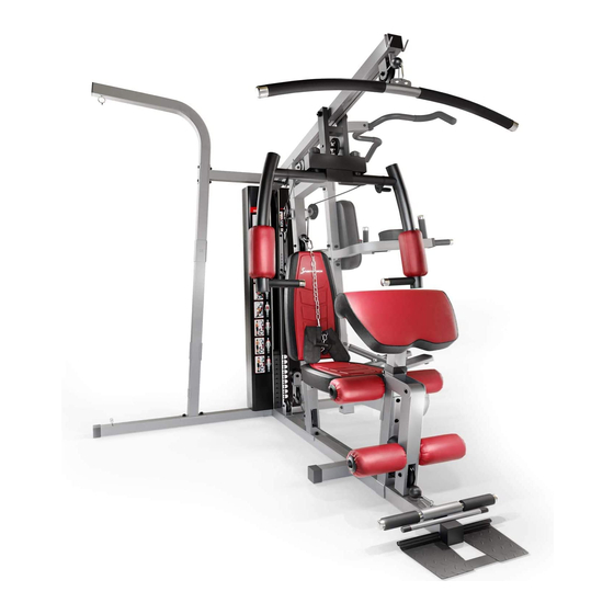
  • Seite 1 HGX250 Three Station Home Gym...
  • Seite 3 Sehr geehrter Kunde wir freuen uns, dass Sie sich für ein Gerät aus der SPORTSTECH Produktpalette entschieden haben. SPORTSTECH Sportgeräte bieten Ihnen höchste Qualität und neueste Technologie. Um die Leistungsfähigkeit des Gerätes voll nutzen zu können und viele Jahre Freude an Ihrem Gerät zu haben, lesen Sie bitte vor der Inbetriebnahme und dem Beginn des Trainings dieses Benutzerhandbuch sorgfältig durch und verwenden Sie das Gerät den Anweisungen entsprechend.
  • Seite 4: Video Tutorials

    Aufbau, Benutzung, Abbau. 1. QR-Code scannen 2. Videos anschauen 3. Schnell und sicher starten Link zu den Videos: https://service.innovamaxx.de/hgx250_video Uns gibt es auch auf Social Media! Hol dir die neuesten Produktinfos, Trainingsinhalte uvm. auf unserer: Instagram-Seite Facebook-Seite https://www.instagram.com/sportstech.de https://www.facebook.com/sportstech.de...
  • Seite 5: Inhaltsverzeichnis

    INHALT INHALT 1. Sicherheitshinweise ....................6 2. Technische Daten .....................7 3. Dies könnte Sie auch interessieren ................8 4. Explosionszeichnung/Ersatzteilliste ................9 5. Aufbauanleitung .......................10 6. Trainings-Informationen .....................31 7. Dehnungsübungen ....................33 8. Reinigung und Pflege ....................34 MONTAGE- UND BEDIENUNGSANLEITUNG - BITTE ZUM SPÄTEREN NACHLESEN AUFBEWAHREN WICHTIG - BITTE LESEN SIE DIESE ANWEISUNGEN VOLLSTÄNDIG, BEVOR SIE MIT DER MONTAGE ODER BENUTZUNG BEGINNEN Diese Anleitung enthält wichtige Informationen, die Ihnen helfen, von Ihrer Ausrüstung optimalen Gebrauch zu machen und eine...
  • Seite 6: Sicherheitshinweise

    1. SICHERHEITSHINWEISE WICHTIG - BITTE VOLLSTÄNDIG DURCHLESEN, BEVOR SIE MIT DER MONTAGE ODER BENUTZUNG BEGINNEN Um das Risiko schwerer Verletzungen zu verringern, lesen Sie die gesamte Anleitung, bevor Sie Ihr Gerät zusammenbauen oder benutzen. Beachten Sie insbesondere die folgenden Vorsichtsmaßnahmen. MONTAGE •...
  • Seite 7: Technische Daten

    • Die Baugröße beträgt: 1896 x 2116 x 2196 mm • Max. Benutzergewicht: 120 kg Das HGX250 ist nach EN ISO 20957-1:2013 & EN 957-2:2003 & EN 20957-8:2017 zertifiziert. Recyclingkreislauf Verpackungsmaterialien können wieder dem Rohstoffkreislauf zugeführt werden. Entsorgen Sie die Verpackung gemäß den aktuellen Bestimmungen. Informationen erhalten Sie bei den Rückgabe- und Sammel-...
  • Seite 8: Dies Könnte Sie Auch Interessieren

    ∙ HOCHWERTIGES MATERIAL: Konstruiert aus dem besten Material, für ein beständiges und beden- kenloses Training. Fitnessmatte ist hoch strapazierfähig und hält enorm viel Gewicht aus. Sie können dieses Produkt in der gewünschten Grösse über folgenden QR-Code oder Link käuflich erwerben. www.sportstech.de/bodenschutzmatte...
  • Seite 9: Explosionszeichnung/Ersatzteilliste

    4. EXPLOSIONSZEICHNUNG/ERSATZTEILLISTE Unter folgendem Link Unter folgendem Link finden Sie die Explosionszeichnung finden Sie die Explosionszeichnung und die Ersatzteile-Liste: und die Ersatzteile-Liste: https://service.innovamaxx.de/hgx250_spareparts https://service.innovamaxx.de/hgx250_spareparts...
  • Seite 10: Aufbauanleitung

    5. AUFBAUANLEITUNG SCHRITT 1 Führen Sie die 2-teilige Führungsstange (18#) in die Bohrungen des hinteren Stabilisators (4#) ein. Richten Sie die Löcher sorgfältig aus und befestigen Sie die Teile mit 2 M10×25mm Inbusschrauben (96#) und 2 Ø10-Unterlegscheiben (105#). Schieben Sie zwei Gummipuffer (54#) entlang der Führungsstangen (18#) nach unten.
  • Seite 11 SCHRITT 2 Befestigen Sie den Hauptträgerrahmen (3#) und den kurzen Stabilisator (148#) am hinteren Stabilisator (4#). Richten Sie die Löcher sorgfältig aus und befestigen Sie mit 2 M10×70mm Schlossschrauben (91#), 1 Halterung (13#), 2 Ø10-Unterlegscheiben (105#) und 2 M10-Schraubenmuttern (103#). Platzieren Sie, auf beiden Seiten, die Halterung (21#) unter den hinteren Stabilisator (4#) und stecken Sie je 2 M10x70mm Schlossschrauben hindurch.
  • Seite 12 SCHRITT 3 Setzen Sie den vorderen vertikalen Rahmen (2#) auf den Hauptträgerrahmen (3#) und sichern Sie mit 2 M10x70 Schlossschrauben (91#), 1 Halterung (21#), 2 Ø10-Unterlegscheiben (105#) und 2 M10-Schraubenmuttern (103#).
  • Seite 13 SCHRITT 4 Dann platzieren Sie 11 Stück 5-Kg Gewichtsplatten (34#) entlang der Führungsstangen (18), stellen Sie dabei sicher, dass die Rillen jeweils nach vorne und nach unten weist. Führen Sie die Wählstange (20#) in das Mittelloch ein und platzieren Sie die kleine 2,5-Kg Gewichtsplatte (35#) auf die anderen Gewichtsplatten.
  • Seite 14 SCHRITT 5 A. Befestigen Sie den oberen Rahmen (1#) am vorderen vertikalen Rahmen (2#) und zwei Führungsstangen (18#). B. Befestigen Sie den vorderen vertikalen Rahmen (2#) mittels 2 M10x70mm Schlossschrauben (91#), 1 Halterung (21#), 2 Ø10mm-Unterlegscheiben (105#) und 2 M10 Schraubenmuttern (103#). C.
  • Seite 15 SCHRITT 6 A. Bringen Sie den unteren Rahmen (111#) am hinteren Stabilisator (4#) an und sichern Sie zusammen mit 2 M10×70mm Schlossschrauben (91#), 1 Halterung (21#), 2 Ø10-Unterlegscheiben (105#) und 2 M10 Schraubenmuttern (103#). B. Setzen Sie den oberen Rahmen (112#) in den unteren Rahmen (111#) und sichern Sie zusammen mit 2 10×70mm Schlossschrauben (91#), 2 Halterungen (144#), 2 Ø10-Unterlegscheiben (105#) und 2 M10 Schraubenmuttern (103#).
  • Seite 16 SCHRITT 7 A. Bringen Sie den unteren Rahmen (149#) am hinteren Stabilisator (4#) an und sichern Sie zusammen mit 2 M10×70mm Schlossschrauben (91#), 1 Halterung (21#), 2 Ø10-Unterlegscheiben (105#) und 2 M10 Schraubenmuttern (103#). B. Setzen Sie den oberen Rahmen (150#) in den unteren Rahmen (149#) und sichern Sie zusammen mit 2 10×70mm Schlossschrauben (91#), 2 Halterungen (144#), 2 Ø10-Unterlegscheiben (105#) und 2 M10 Schraubenmuttern (103#).
  • Seite 17 SCHRITT 8 Befestigen Sie die Sitzpolsterstütze (6#) am vorderen vertikalen Rahmen (2#) und befestigen diese mit 2 M10×70mm Schlossschrauben (91#), 1 Halterung (21#), 2 Ø10-Unterlegscheiben (105#) und 2 M10-Schraubenmuttern (103#). Befestigen Sie den Beinzughalter (5#) wie in der Abbildung gezeigt. Sichern Sie ihn mit dem Hauptträgerrahmen und der Sitzpolsterstütze (6#) mittels 3 M10x70mm Schlossschrauben (91#), 1 Halterung (21#), 3 Ø10-Unterlegscheiben (105#) und 3 M10-Schraubenmuttern (103#).
  • Seite 18 SCHRITT 9 Setzen Sie die vordere Grundplatte (9#) am oberen Rahmen (1#) an und befestigen Sie zusammen mit 2 M10-Schraubenmuttern (103#), 2 großen Unterlegscheiben (107#), 1 Achse (109#).
  • Seite 19 SCHRITT 10 Bringen Sie die rechte Seitenausleger-Einstellung (25#) durch das Loch der vorderen Grundplatte an und befestigen Sie mit 1 Abstandhalter (71#), Abdeckung (53#), 1 M6-Schraubenmutter (104#) und 1 M6x33mm Inbusschraube (142#). Befestigen Sie den rechten Seitenausleger (10#) an der rechten Seitenausleger-Einstellung (25#) und sichern Sie zusammen mittels 1 M8×23 Inbusschraube (90#), 1 Kunststoff-Unterlegscheiben (73#),1 Unterlegscheibe Ø6 (108#) und 1 M6-Schraubenmutter (104#).
  • Seite 20 SCHRITT 11 Befestigen Sie das Armcurl-Pad (33#) an der Armcurl-Pad-Halterung (14#) und befestigen Sie es mit 2 M8×16mm Inbusschrauben (97#) und 2 Ø8-Unterlegscheiben (106#).Setzen Sie den Armcurl-Pad-Halter in die Öffnung des Beinzughalters ein und wählen Sie die gewünschte Höhe mit dem Knopf (51#). Bringen Sie den Beinzug (8#) am Beinzughalter (5#) an und befestigen beide mit 1 M10x80mm Inbusschraube (98#), 2 Ø10- Unterlegscheiben (105#) und 2 Buchsen (56#) sowie 1 M10-Schraubenmutter (103#).
  • Seite 21 SCHRITT 12 Befestigen Sie das Sitzpolster (31#) auf dem Sitzpolster-Einstellrahmen (7#) und sichern Sie mit 4 M8×16mm Inbusschrauben (97#) und 4 Ø8-Unterlegscheiben (106#). Führen Sie den Sitzpolster-Einstellrahmen (7#) in die Bohrung ein und wählen Sie die gewünschte Höhe mit dem Verriegelungsknopf (85#). Befestigen Sie die Rückenpolsterstütze (27#) mittes M10x110 Inbusschraube (101#), Ø10-Unterlegscheibe (105#) und einer M10 Schraubenmutter (103#) am vorderen vertikalen Rahmen (2#).
  • Seite 22 SCHRITT 13 Befestigen Sie das Schaumstoffrohr (22#) in den Löchern, so wie im Diagramm gezeigt, und befestigen Sie 4 Schaumstoffrollen (36#) und Endkappen (86#) an beiden Enden. Sichern Sie die Fußplatte (29#) mit dem Fußplattenrohr (28#) und befestigen Sie dann Endkappen (50#) an beiden Enden.
  • Seite 23 SCHRITT 14 Setzen Sie den linken und rechten Arm (114# bzw. 115#) am unteren Rahmen an, wie in der Abbildung gezeigt, und sichern Sie sie mit 4 M8×10mm Inbusschrauben (133#), 4 Ø8-Unterlegscheiben (106#), 1 Halterung (122#). Befestigen Sie den linken und rechten Arm (114# bzw. 115#) zusammen mit 1 M12×75 mm Inbusschraube (#134), 2 Ø12- Unterlegscheiben (139#), 1 M12 Schraubenmutter (#135).
  • Seite 24 SCHRITT 15 Befestigen Sie das Rückenpolster (120#) wie in der Abbildung gezeigt mit 2 M8×70mm Inbusschrauben (137#) und 2 Ø8- Unterlegscheiben (106#). Befestigen Sie die beiden Armpolster (121#) wie in der Abbildung dargestellt und sichern diese mit 4 M8×60 mm Inbusschrauben (136#) und 4 Ø8-Unterlegscheiben (106#).
  • Seite 25 SCHRITT 16 A. Bringen Sie das 3890 mm lange obere Kabel (39#) durch die Öffnung des oberen Rahmens. Stellen Sie sicher, dass sich der Kugelanschlag vor dem oberen Rahmen befindet. Platzieren Sie 1 Seilrolle (74#) unterhalb des Kabels und sichern diese mittels 1 M10×45 Inbusschraube (94#), 2 ø10-Unterlegscheiben (105#) und 1 M10-Schraubenmutter (103#).
  • Seite 26 SCHRITT 17 A. Befestigen Sie das Ende des 3070 mm langen Schmetterlingsdrähte (38#) am Haken. B. Befestigen Sie die 2-teilige Seilrollenhalterung (15#), wie in der Abbildung gezeigt, und sichern Sie mit 1 M10×65mm Inbusschraube (#93), 2 Ø10-Unterlegscheiben (105#) und 1 M10-Schraubenmutter (103#). C.
  • Seite 27 SCHRITT 18 A. Bringen Sie das Ende des 3890MM langen unteren Kabels (136#) durch die Bohrung des Beinzuges und platzieren Sie 1 Seilrolle an dem Kabel. Sichern Sie es mit 1 M10x60 mm Inbusschraube (102#), 2 Buchsen (42#) und 1 M10-Schraubenmutter (103#).
  • Seite 28 SCHRITT 19 Befestigen Sie die 2-teilige Abdeckung für die Gewichte (17#) wie in der Abbildung dargestellt, und sichern diese mit 8 M10x20 Inbusschrauben (92#), 8 Ø10 -Unterlegscheiben (105#) und 2 Klammern (141#).
  • Seite 29 SCHRITT 20 Befestigen Sie die Hydrozylinderhalterung (123#) am unteren Rahmen (111#) und sichern Sie mit 2 M10x70mm Schlossschrauben (91#), 4 Ø10-Unterlegscheiben (105#), 1 Halterung (147#) und 2 M10-Schraubenmuttern (103#). Befestigen Sie den linken und rechten Pedalrahmen (118# bzw. 117#) an der Achse des unteren Rahmens (111#) und sichern Sie diese mit 2 M8×16mm Inbusschrauben (97#) und 2 Ø8-Unterlegcheiben (145#).
  • Seite 30 SCHRITT 21 Befestigen Sie die Latzugstange (19#) am Ende des oberen Kabels mit 2 Haken (47#) und 15-gliedriger Kette (49#). Befestigen Sie den Bauchgurt (83#) an der Schließe (58#) und sichern Sie zusammen mit 1 M10x30mm Inbusschraube (87#), 2 Ø10-Unterlegscheiben (105#) und 1 M10-Schraubenmutter (103#).
  • Seite 31: Trainings-Informationen

    6. TRAININGS-INFORMATIONEN BEVOR SIE BEGINNEN Vor Trainingsbeginn sollten Sie Ihre körperliche Verfassung berücksichtigen. Wenn Sie längere Zeit sportlich inaktiv waren, sollten Sie mit kleineren Trainingseinheiten starten. Ihre aerobe Fitness sollte sich jedenfalls innerhalb der nächsten sechs bis acht Wochen verbessern. Und seien Sie bitte nicht entmutigt, falls es etwas länger dauert.
  • Seite 32 Um Ihre Herzfrequenz zu messen, hören Sie auf zu trainieren, bewegen Sie jedoch weiter Ihre Beine oder gehen Sie etwas umher und legen Sie zwei Finger auf die Innenseite Ihres Handgelenks. Erfassen Sie Ihre Herzschlagzahl über sechs Sekunden hinweg und multiplizieren Sie das Ergebnis mit 10, um Ihre Herzfrequenz zu bestimmen. Zum Beispiel, wenn Ihre Herzschlagzahl innerhalb des Sechs-Sekunden-Zeitraums 14 beträgt, ist Ihre Herzfrequenz 140 Schläge pro Minute.
  • Seite 33: Dehnungsübungen

    7. DEHNUNGSÜBUNGEN Bevor Sie das Laufband benutzen, ist es am besten, 5 bis 10 Minuten zum Aufwärmen Stretching- Übungen durchzuführen. Dehnen vor dem Training hilft die Flexibilität zu verbessern und das Verletzungsrisiko zu mindern. MIT DEM KOPF ROLLEN Drehen Sie den Kopf nach rechts für eine Sekunde, fühlen Sie die Streckung auf der linken Seite des Nackens, dann drehen Sie den Kopf zurück für eine Sekunde, recken Sie Ihr Kinn nach oben und lassen Ihren Mund geöffnet.
  • Seite 34: Reinigung Und Pflege

    8. REINIGUNG UND PFLEGE 1. Die Sicherheit des Gerätes kann nur aufrechterhalten werden, wenn es regelmäßig auf Verschleiß und/oder Abnutzung geprüft wird, z. B. an den Verbindungspunkten. 2. Schmieren Sie bewegliche Teile regelmäßig mit Schmieröl ab, um vorzeitigem Verschleiß vorzubeugen. 3.
  • Seite 35 Dear customer, We are pleased you chose a device from the SPORTSTECH product range. With sports equipment from SPORTSTECH you get the highest quality and latest technology. In order to fully use the potential of your device and be able to enjoy it for many years, please read this manual carefully before starting up and beginning of training, and use the device according to the instruc- tions.
  • Seite 36 1. Scan the QR code 2. Watch videos 3. Start fast and safely Link to the videos: https://service.innovamaxx.de/hgx250_video We are also on social media! Get the latest product information, training content and much more on our: Instagram-page Facebook-page https://www.instagram.com/sportstech.de https://www.facebook.com/sportstech.de...
  • Seite 37 INDEX INHALT 1. Safety Information ....................39 2. Technical Specification ....................40 3. you may also interested in these accessoires ...............41 4. exploded drawing/spare parts list................42 5. Assembly instructions ....................43 6. Exercising Information ....................64 7. Stretch exercise .......................66 8. Care and Maintenance ....................67 ASSEMBLY &...
  • Seite 38: Safety Information

    1. SAFETY INFORMATION IMPORTANT – PLEASE READ FULLY BEFORE ASSEMBLY OR USE To reduce the risk of serious injury, read the entire manual before you assemble or use your bench. In particular, note the following safety precautions. ASSEMBLY • Check you have all the components and tools listed in the parts list, bearing in mind that, for ease of assembly, some components are pre-assembled.
  • Seite 39: Technical Specification

    The assembly size is: 1896*2116*2196MM • Max. user weight: 120 kg The HGX250 is certified to EN ISO 20957-1:2013 & EN 957-2:2003 & EN ISO 20957-8:2017. Recycling loop Packaging material can be conveyed back to the raw material cycle. Dispose of packaging material in accordance with legal...
  • Seite 40: You May Also Interested In These Accessoires

    The ideal protection. For your home workout. Sportstech has a floor protection mat to prevent your fitness equipment from damaging your floor at home. Of course it is available in different sizes and can also be used for yoga or other exercises. It protects your floor from marks, dirt or scratches.
  • Seite 41: Exploded Drawing/Spare Parts List

    4. EXPLODED DRAWING/SPARE PARTS LIST At the following link At the following link you will find the exploded drawing you will find the exploded drawing and the spare parts list: and the spare parts list: https://service.innovamaxx.de/hgx250_spareparts https://service.innovamaxx.de/hgx250_spareparts...
  • Seite 42: Assembly Instructions

    5. ASSEMBLY INSTRUCTIONS STEP 1 Insert the 2pcs guide rod(18#) into the holes of the rear stabiliser(4#), Carefully align the holes and secure them with 2pcs M10×25mm Allen bolt (96#), 2pcs Ø10 washer(105#). Slide two rubber bumper (54#) down along the guide rods (18#).
  • Seite 43 STEP 2 Attach the Main Frame (3 #) and the Short Stabilizer (148 #) to the Rear Stabilizer (4 #). Carefully align and secure the holes with 2 M10 × 70mm carriage bolts (91 #), 1 bracket (13 #), 2 Ø10 washers (105 #) and 2 M10 nuts (103 #). On both sides, place the bracket (21 #) under the rear stabilizer (4 #) and insert 2 M10x70mm carriage bolts.
  • Seite 44 STEP 3 Place the front vertical frame(2#) onto the main base frame (3#) and secure them with 2pcsM10*70 Carriage bolt(91#),1pc bracket(21#),2pcs Ø10 washer (105#) and 2pcs M10 Aircraft nut (103#).
  • Seite 45 STEP 4 Then place 11 pieces of 5-Kg Weight plates (34 #) along the guide rods (18), making sure that the forward and backward grooves point down. Insert the selector rod(20#) into the center hole and place the small 2.5-Kg weight plate (35 #) above the other weight plates.
  • Seite 46 STEP 5 A.) Attach the upper frame (1#) onto the front vertical frame(2#) and two Guide rods (18#). B.) Fix to front vertical frame(2#) using 2pcs M10 x 70mm Carriage Bolts (91#), 1 pc Bracket (21#), 2pcs Ø10mm Washers (105#) and 2pcs M10 Aircraft nuts (103#). C.)Place the Connection frame(124#)onto the rear of the front vertical frame using M10 x 25mm Allen Bolts (96#) and Ø10mm Washers (105#).
  • Seite 47 STEP 6 a.)Place the lower frame (111#) onto the rear stabiliser (4#) and secure them together with 2pcs M10×70mm Carriage bolt(91#),1pc bracket(21#),2pcs Ø10 washer (105#) and 2pcs M10 Aircraft nut(103#). b.)Insert the upper frame (112#) into the lower frame(111#), and secure them together with 2pcs M10×70mm Carriage bolt (91#),2pcs bracket (144#),2pcs Ø10 washer(105#) and 2pcs M10 Aircraft nut (103#).
  • Seite 48 STEP 7 a.)Place the lower frame (149#) onto the rear stabiliser (4#) and secure them together with 2pcs M10×70mm Carriage bolt(91#),1pc bracket(21#),2pcs Ø10 washer (105#) and 2pcs M10 Aircraft nut(103#). b.)Insert the upper frame (150#) into the lower frame(149#), and secure them together with 2pcs M10×70mm Carriage bolt (91#),2pcs bracket (144#),2pcs Ø10 washer(105#) and 2pcs M10 Aircraft nut (103#).
  • Seite 49 STEP 8 a.) Attach the seat pad support (6#) to the front vertical frame(2#) and secure them together with 2pcs M10×70mm Carriage bolt (91#),1pc bracket (21#),2pcs Ø10 washer (105#) and 2pcs M10 Aircraft nut (103#). B.)Attach the leg developer holder (5#) as the diagram shows.and secure it with the main base frame and seat pad support (6#) with 3 pcs M10*70 Carriage bolt (91#),1pc bracket (21#),3pc Ø10 washer (105#) and 3pc M10 Aircraft nut (103#).
  • Seite 50 STEP 9 Attach the front press base (9#) to the upper frame(1#) and secure them together with 2pcsM10 Aircraft nut (103#),2pcs big washer (107#),1pc axle (109#).
  • Seite 51 STEP 10 Attach the right butterfly adjustment(25#) through the hole of the front press base and secure them with 1pc spacer (71#),cover(53#), 1pc M6 Aircraft nut (104#) and 1pc M6X33 Allen bolt(142#). Attach the right butterfly (10#) to the right butterfly adjustment(25#) and secure them together 1pc M8×23 Allen bolt (90#),1 pcs plastic washer(73#), 1 pc Ø6 washer (108#) and 1pc M6 Aircraft nut (104#).
  • Seite 52 STEP 11 Attach the arm curl pad (33#) to the arm curl pad support (14#) and secure them with 2pcs M8×16 Allen bolt (97#) and 2pcs Ø8 washer (106#).Insert the arm curl pad support into the opening of the leg developer holder and select the desired height with the lick knob(51#).
  • Seite 53 STEP 12 Attach the seat pad (31#) onto the seat pad adjustment frame(7#) and secure them with 4pcs M8×16 Allen bolt (97#)and 4pcs Ø8 washer (106#).Insert the seat pad adjustment frame(7#) into the hole and select the desired height with the lock knob(85#). Attach the Back Cushion Support (27 #) to the front vertical frame (2 #) with M10x110 Allen Screw (101 #), Ø10 Washer (105 #), and M10 Screw Nut (103 #).
  • Seite 54 STEP 13 Attach the foam roll tube (22#) into the holes as the diagram shows, And attach the 4pcs foam roll(36#) and end cap (86#) from both ends. Secure the foot plate (29#) with the foot plate tube(28#) and then attach the end cap (50#) from both ends.
  • Seite 55 STEP 14 Attach the Left & Right dip arm (114#&115#) to the lower frame as the diagram shows,and secure them with 4 pcs M8×10mm Allen bolt (133#),4pcs Ø8 washer (106#), 1pc bracket (122#). Attach the Left & Right dip arm (114#&115#) together with 1 pc M12×75mm Allen bolt (#134), 2pcs Ø12washer (139#), 1pcM12aircraft nut (#135).
  • Seite 56 STEP 15 Secure the backrest pad (120#) as the diagram shows with 2pcs M8×70mmAllen bolt (137#) and 2pcs Ø8 washer (106#). Attach the 2pcs arm pad(121#) as the diagram show and secure them with 4pcs M8×60mm Allen bolt (136#) and 4 pcs Ø8 washer (106#).
  • Seite 57 STEP 16 A Attach the 3890 mm Upper cable (39#) through the opening of the upper frame , Make sure the ball stopper should be in front of the upper frame, Place 1PC Pulley (74#) below the cable and secure the 1st pulley using 1PC M10 × 45 Allen bolt (94#) ,2PC ø10 washer (105#) and 1pc M10 Aircraft nut (103#).
  • Seite 58 STEP 17 A Attach the end of the 3070 MM butterfly cable(38#) to the hook . B. Attach the 2pcs swivel pulley bracket(15#) as the diagram shows and secureit with 1 pc M10×65mmallen bolt (#93),2pcs Ø10 washer (105#), 1 pc M10 aircraft nut (103#). C.
  • Seite 59 STEP 18 A. Attach the end of 3890MM lower cable(136#) through the opening of the leg developer,Place 1 pc pulley onto the cable, Secure it with 1PC M10X60 Allen bolt (102#),2pcs bushing (42#) and 1pc M10 Aircraft nut (103#). B. Draw the cable backwards,place 1pc pulley onto the cable, secure it with 1PC M10X65 Allen bolt (93#),2pcs bushing (41#) and 1pc M10 Aircraft nut (103#).
  • Seite 60 STEP 19 Attach the 2pcs weight stack cover (17#) as the diagram shows , secure them with 8pcs M10*20 Allen bolt(92#),8pcs Ø10 washer (105#) and 2 pcs bracket(141#).
  • Seite 61 STEP 20 Attach the hydro-cylinder bracket (123#) to the lower frame(111#) and secure them with 2pcsM10*70 Carriage bolt(91#),4pcs Ø10 washer (105#) ,1 pc bracket(147#)and 2 pcs M10 Aircraft nut(103#). Attach the left&right pedal frame(118#&117#) to the axle of the lower frame(111#) and secure them with 2pcs M8×16allen bolt (97#), 2pcs Ø8washer (145#).
  • Seite 62 STEP 21 Attach the lat bar(19#) to the end of the high cable with 2pcs 7# gourd hook(47#) and 15 joint chain(49#). Attach the abdominal strap(83#) to the buckle(58#) and secure them together with 1pcM10*30 allen bolt (87#),2pcs Ø10 washer (105#) and 1 pcM10 Aircraft nut(103#).
  • Seite 63: Exercising Information

    6. EXERCISING INFORMATION BEFORE YOU START How you begin your exercise programme depends on your physical condition. If you have been inactive for several years or are overweight, you must start slowly and increase a few repetitions per workout. However, your aerobic fitness will improve over the next six to eight weeks. Don’t be discouraged if it takes longer. It’s important to work at your own pace.
  • Seite 64 MUSCLE CHART AEROBIC EXERCISE Aerobic exercise improves the fitness of your lungs and heart - your body’s most important muscle. Aerobic exercise fitness is promoted by any activity that uses your large muscles (arms, legs or buttocks, for example). Your heart beats quickly and you breathe deeply.
  • Seite 65: Stretch Exercise

    7. STRETCH EXERCISE No matter how you do sports, please do some stretch at first, The warm muscle will extend easily, so warm up yourself with 5-10minutes, Then We suggest the following stretch exercise, five times.10 counts for each time or longer do these exercise again after sports. HEAD ROLLS Rotate your head to the right for one count, feeling the stretch up the left side of your neck, then rotate your head back for one count, stretching your chin to the ceiling and letting your mouth open.
  • Seite 66: Care And Maintenance

    8. CARE AND MAINTENANCE 1. The safety level of the equipment can only be maintained if it is examined regularly for damage and wear e.g. connection points. 2. Lubricate moving parts with light oil periodically to prevent premature wear. 3. Inspect and tighten all parts before using the equipment, replace any defective parts immediately, and do not use the equipment again until it is in perfect working order.
  • Seite 67 Estimado cliente, Nos complace que haya elegido un dispositivo de la línea de productos SPORTSTECH. Con el equipo deportivo de SPORTSTECH usted obtiene la más alta calidad y la mejor tecnología. Con el fin de usar todo el potencial de su dispositivo y para que pueda disfrutarlo durante muchos años, por favor lea este manual cuidadosamente antes de comenzar a ejercitarse, y use el dispositivo de acuer- do a las instrucciones.
  • Seite 68 Montaje, Utilizar, Desmontaje. 1. Escanear el código QR 2. Ver vídeos 3. Comienza rápido y seguro Enlace a los videos: https://service.innovamaxx.de/hgx250_video ¡También estamos en redes sociales! Obtenga la última información sobre nuestros productos, entrenamientos y mucho más aquí: Instagram Facebook https://www.instagram.com/sportstech.de https://www.facebook.com/sportstech.de...
  • Seite 69 CONTENIDOS INHALT 1. Información de seguridad ..................72 2. Especificationes Técnicas ..................73 3. También podría interesarle ..................74 4. dibujo de explsoión/lista de repuestos .................75 5. Instrucciones de ensamblaje ..................76 6. Información de ejercicios...................97 7. Ejercicios de estiramiento ..................99 8. Cuidado y mantenimiento ..................100 MANUAL DE USUARIO E INSTRUCCIONES DE ENSAMBLAJE - POR FAVOR GUARDAR PARA FUTURA REFERENCIA IMPORTANTE –...
  • Seite 70: Información De Seguridad

    1. INFORMACIÓN DE SEGURIDAD IMPORTANTE – POR FAVOR LEA CUIDADOSAMENTE ANTES DE ENSAM- BLAR O USAR EL DISPOSITIVO Para reducir el riesgo de lesiones serias, lea todo el manual antes de ensamblar o usar su banco de ejercicios. En particular, tenga en cuenta las siguientes precauciones de seguridad.
  • Seite 71: Especificationes Técnicas

    El tamaño de montaje es: 1896*2116*2196MM • Max. Peso del usuario: 120 kg El HGX250 ha sido certificado por las normas EN ISO 20957-1:2013 & EN 957- 2:2003 & EN ISO 20957-8:2017. Reciclaje loop El material de empaque puede trasladarse de nuevo al ciclo de materias primas. Deshágase del material de empaque de acuerdo a...
  • Seite 72: También Podría Interesarle

    Para que el suelo de su casa no sufra daños por parte de su equipo de ejercicios, utilice la alfombril- la protectora de Sportstech. Por supuesto, está disponible en diferentes tamaños y también se pue- de utilizar para yoga u otros ejercicios. Protege su piso de huellas, suciedad o arañazos. Mano de obra de alta calidad y una superficie especial evitan marcas de los dispositivos que se encuentran sobre la alfombrilla.
  • Seite 73: Dibujo De Explsoión/Lista De Repuestos

    4. DIBUJO DE EXPLSOIÓN/LISTA DE REPUESTOS En el siguiente enlace En el siguiente enlace encontrarás el dibujo de explosión encontrarás el dibujo de explosión y la lista de repuestos: y la lista de repuestos: https://service.innovamaxx.de/hgx250_spareparts https://service.innovamaxx.de/hgx250_spareparts...
  • Seite 74: Instrucciones De Ensamblaje

    5. INSTRUCCIONES DE ENSAMBLAJE PASO 1 Inserte la 2 barras guía (18#) en los agujeros del estabilizador posterior (4#), alinee cuidadosamente los agujeros y asegúrelos con 2 tornillos Allen de M10×25mm (96#), y 2 arandelas de Ø10 (105#). Deslice dos topes de goma (54#) hacia abajo a lo largo de las barras guía (18#).
  • Seite 75 PASO 2 Conecte el marco base principal (3#) y el estabilizador corto (148#) al estabilizador posterior (4#). Alinee cuidadosamente los orificios y fíjelos en su lugar. con 2 tornillos M10×70mm (91#), un soporte (13#), 2 arandelas de Ø10 (105#) y 2 tuercas M10 (103#).
  • Seite 76 PASO 3 Ubique el marco vertical frontal (2#) en el marco base principal (3#) y asegúrelos con 2 tornillos M10*70mm (91#),1 soporte (21#), 2 arandelas Ø10 (105#) y 2 tuercas M10 (103#).
  • Seite 77 PASO 4 Luego coloque 11 placas de peso de 5 Kg. (34#) a lo largo de las barras de guía (18), asegurándose de que las ranuras estén orientadas hacia adelante y hacia abajo. Inserte la barra selectora (20#) en el agujero central y coloque la pequeña placa de peso de 2,5-kg (35 #) en las otras placas de peso.
  • Seite 78 PASO 5 A.) Conecte el marco superior (1#) en el marco vertical frontal (2#) y en las dos barras guía (18#). B.) Asegure el marco superior (2#) usando 2 tornillos M10 x 70mm (91#), 1 soporte (21#), 2 arandelas Ø10mm (105#) y 2 tuercas M10 (103#).
  • Seite 79 PASO 6 a.) Ubique el marco inferior (111#) en el estabilizador posterior (4#) y asegúrelos con 2 tornillos M10×70mm (91#), 1 soporte (21#), 2 arandelas Ø10 (105#) y 2 tuercasM10 (103#). b.) Inserte el marco superior (112#) en el marco inferior (111#) y asegúrelos con 2 tornillos M10×70mm (91#), 2 soportes (144#), 2 arandelas Ø10 (105#) y 2 tuercas M10 (103#).
  • Seite 80 PASO 7 a.) Ubique el marco inferior (149#) en el estabilizador posterior (4#) y asegúrelos con 2 tornillos M10×70mm (91#), 1 soporte (21#), 2 arandelas Ø10 (105#) y 2 tuercasM10 (103#). b.) Inserte el marco superior (150#) en el marco inferior (149#) y asegúrelos con 2 tornillos M10×70mm (91#), 2 soportes (144#), 2 arandelas Ø10 (105#) y 2 tuercas M10 (103#).
  • Seite 81 PASO 8 A.) Conecte el soporte del asiento (6#) al marco vertical frontal (2#) y asegúrelos con 2 tornillos M10×70mm (91#), 1 soporte (21#), 2 arandelas Ø10 (105#) y 2 tuercas M10 (103#). B.) Conecte el soporte para el ejercitador de piernas (5#) como muestra el diagrama y asegúrelo con el marco base principal y con el soporte del asiento (6#) con 3 tornillos M10*70 (91#), 1 soporte (21#),3 arandelas Ø10 (105#) y 3 tuercas M10 (103#).
  • Seite 82 PASO 9 Conecte el soporte de presión frontal (9#) al marco superior (1#) y asegúrelos juntos con 2 tuercas M10 (103#), 2 arandelas grandes (107#) y 1 eje (109#).
  • Seite 83 PASO 10 Conecte el ajuste mariposa derecho (25#) a través del agujero del soporte de presión frontal y asegúrelos con 1 espaciador (71#), cubierta (53#), 1 tuerca M6 (104#) y 1 tornillo Allen M6X33 (142#). Conecte la mariposa derecha (10#) al ajuste mariposa derecho (25#) y asegúrelos con 1 tornillo Allen M8×23 (90#), 1 arandelas plásticas (73#), 1 arandela Ø6 (108#) y 1 tuerca M6 (104#).
  • Seite 84 PASO 11 Conecte la almohadilla curva para brazos (33#) al soporte de la almohadilla para brazos (14#) y asegúrelos con 2 tornillos Allen M8×16 (97#) y 2 arandelas Ø8 (106#). Inserte el soporte de la almohadilla para brazos en la abertura del soporte para el ejercitador de piernas y seleccione la altura deseada con la perilla (51#).
  • Seite 85 PASO 12 Conecte el asiento (31#) en el marco de ajuste del asiento (7#) y asegúrelos con 4 tornillos Allen M8×16 (97#) y 4 arandelas Ø8 (106#). Inserte el marco de ajuste del asiento (7#) en el agujero y seleccione la altura deseada con la perilla de bloqueo (85#). Fije el soporte del respaldo (27#) a la estructura vertical trasera (2#) con el tornillo Allen M10x110 (101#), la arandela de Ø10 (105#) y una tuerca M10 (103#).
  • Seite 86 PASO 13 Conecte el tubo de espuma (22#) a los agujeros como muestra el diagrama y conecte los 4 rodillos de espuma (36#) y las tapas de extremo (86#) desde ambos extremos. Asegure la placa para los pies (29#) con el tubo de la placa para pies (28#) y después conecte las tapas de extremo (50#) desde ambos extremos.
  • Seite 87 PASO 14 Conecte la sección izquierda y derecha para fondos (114#&115#) al marco inferior como muestra el diagrama y asegúrelos con 4 tornillos Allen M8×10mm (133#), 4 arandelas Ø8 (106#) y 1 soporte (122#). Conecte la sección izquierda y derecha para fondos (114#&115#) con 1 tornillo Allen M12×75mm (#134) 2 arandelas Ø12 (139#) y 1 tuerca M12 (#135).
  • Seite 88 PASO 15 Asegure el respaldo (120#) como muestra el diagrama con 2 tornillos Allen M8×70mm (137#) y 2 arandelas Ø8 (106#). Conecte las 2 almohadillas para brazos (121#) como muestra el diagrama y asegúrelas con 4 tornillos Allen M8×60mm (136#) y 4 arandelas Ø8 (106#).
  • Seite 89 PASO 16 A Conecte el cable superior de 3890 mm (39#) a través de la abertura del marco superior, asegúrese de que el tapón circular esté en la parte frontal del marco superior, ponga 1 polea (74#) debajo del cable y asegure la 1ra polea usando 1 tornillo Allen M10 ×...
  • Seite 90 PASO 17 A Conecte el extremo del cable mariposa 3070 MM (38#) al gancho. B. Conecte los dos soportes giratorios para polea (15#) como muestra el diagrama y asegúrelos con 1 tornillo Allen M10×65mm (#93), 2 arandelas Ø10 (105#) y 1 tuerca M10 (103#). C.
  • Seite 91 PASO 18 A. Conecte el extremo del cable inferior 3890MM (136#) a través de la abertura del ejercitador de piernas, ponga 1 polea en el cable, asegúrela con 1 tornillo Allen M10X60 (102#), 2 casquillos (42#) y 1 tuerca M10 (103#). B.
  • Seite 92 PASO 19 Conecte las cubiertas para la columna de pesas (17#) como muestra el diagrama, asegúrelas con 8 tornillos Allen 8pcs M10*20 (92#), 8 arandelas Ø10 (105#) y 2 soportes (141#).
  • Seite 93 PASO 20 Conecte el soporte de los hidrocilindros (123#) al marco inferior (111#) y asegúrelos con 2 tornillos M10*70 (91#),4 arandelas Ø10 (105#) ,1 soporte (147#) y 2 tuercas M10 (103#). Conecte el soporte izquierdo y derecho para pedales (118#&117#) al eje del marco inferior (111#) y asegúrelos con 2 tornillos Allen M8×16 (97#) y 2 arandelas Ø8 (145#).
  • Seite 94 PASO 21 Conecte la barra lat (19#) al extremo del cable superior con 2 ganchos (47#) y la cadena de 15 eslabones (49#). Conecte la correa abdominal (83#) a la hebilla (58#) y asegúrela con 1 tornillo Allen M10*30 (87#), 2 arandelas Ø10 (105#) y 1 tuerca M10 (103#).
  • Seite 95: Información De Ejercicios

    6. INFORMACIÓN DE EJERCICIOS ANTES DE COMENZAR El comienzo de su programa de ejercicios depende de su condición física. Si ha estado inactivo durante varios años o tiene sobrepeso, debe comenzar lentamente y aumente unas cuantas repeticiones por ejercicio. Sin embargo, su capacidad aeróbica mejorará durante las siguientes seis u ocho semanas. No se desanime si toma más tiempo. Es importante que se ejercite a su propio ritmo.
  • Seite 96 TABLA MUSCULAR EJERCICIO AERÓBICO El ejercicio aeróbico mejora el estado físico de sus pulmones y corazón - el musculo más importante de su cuerpo. El ejercicio aeróbico es fomentado por cualquier actividad que use sus músculos grandes (brazos, piernas o glúteos, por ejemplo). Su corazón late rápidamente y usted respira profundamente.
  • Seite 97: Ejercicios De Estiramiento

    7. EJERCICIOS DE ESTIRAMIENTO No importa cómo se ejercite, siempre haga algo de estiramiento primero. El calentamiento muscular hará que sus músculos se extiendan fácilmente, así que caliente al menos 5-10 minutos. Luego le sugerimos hacer los siguientes ejercicios de estiramiento cinco veces. El estiramiento antes del ejercicio le ayuda a mejorar la flexibilidad y reduce los riesgos de lesiones.
  • Seite 98: Cuidado Y Mantenimiento

    8. CUIDADO Y MANTENIMIENTO 1. El nivel de seguridad del dispositivo sólo puede mantenerse si se examina de manera regular en busca de daños y desgaste, por ejemplo, en puntos de conexión. 2. Lubrique las piezas móviles con aceite suave periódicamente para evitar un desgaste prematuro. 3.
  • Seite 99 FRANÇAIS Cher client, Nous sommes ravis que vous ayez choisi un appareil de la gamme de produits SPORTSTECH. Avec les équipements sportifs de SPORTSTECH, vous obtenez la plus haute qualité et la meilleure technologie. Afin d'utiliser pleinement le potentiel de votre appareil et de pouvoir l'apprécier pendant de nombreuses années, lisez attentivement ce manuel avant l'utilisation et le début de votre entraînement et utilisez l'ap-...
  • Seite 100 3. Démarrez rapidement et en toute sécurité Lien vers les vidéos: https://service.innovamaxx.de/hgx250_video Vous pouvez aussi nous trouver sur les réseaux sociaux! Retrouve les dernières informations sur les produits, le contenu des entraînements et bien plus encore sur notre: la page Instagram la page Facebook https://www.instagram.com/sportstech.de https://www.facebook.com/sportstech.de...
  • Seite 101 CONTENU INHALT 1. Informations de sécurité ....................105 2. Spécifications Techniques ..................106 3. Cela pourrait aussi vous intéresser ................107 4. dessin éclaté/liste des pièces de rechange ..............108 5. Instructions d'assemblage ..................109 6. Informations sur les exercices ..................130 7. Excercice d'étirement ....................132 8.
  • Seite 102: Informations De Sécurité

    1. INFORMATIONS DE SÉCURITÉ IMPORTANT - VEUILLEZ LIRE ENTIÈREMENT AVANT TOUT ASSEMBLAGE OU UTILISATION Pour réduire le risque de blessure grave, lisez le manuel en entier avant d‘assembler ou d‘utiliser votre banc. En particulier, notez les précautions de sécurité suivantes. ASSEMBLAGE •...
  • Seite 103: Spécifications Techniques

    La taille de l‘ensemble est: 1896*2116*2196MM • Max. Poid de l‘utilisateur: 120 kg Le HGX250 répond aux Normes EN ISO 20957-1:2013 & EN 957-2:2003 & EN ISO 20957-8:2017. Chaîne du recyclage Les matériaux d‘emballage peuvent être transportés vers le cycle des matières premières. La disposition des matériaux d‘emballage,...
  • Seite 104: Cela Pourrait Aussi Vous Intéresser

    Afin que votre sol ne soit pas endommagé par votre équipement de fitness, il existe un tapis de protection Sportstech. Il est disponible en différentes tailles et peut également être utilisé pour le yoga ou d'autres exercices. Il protège votre sol contre les traces de pas, la saleté ou les rayures. La fabrication de haute qualité...
  • Seite 105: Dessin Éclaté/Liste Des Pièces De Rechange

    4. DESSIN ÉCLATÉ/LISTE DES PIÈCES DE RECHANGE A l‘adresse suivante A l‘adresse suivante vous trouverez le dessin éclaté vous trouverez le dessin éclaté et la liste des pièces de rechange: et la liste des pièces de rechange: https://service.innovamaxx.de/hgx250_spareparts https://service.innovamaxx.de/hgx250_spareparts...
  • Seite 106: Instructions D'assemblage

    5. INSTRUCTIONS D'ASSEMBLAGE ÉTAPE 1 Insérez la tige de guidage 2 pièces (18 #) dans les trous du stabilisateur arrière (4 #). Alignez soigneusement les trous et fixez-les avec 2 boulons Allen M10 × 25mm (96 #) et 2 rondelles Ø10 (105 #). Faites glisser deux pare-chocs en caoutchouc (54 #) le long des tiges de guidage (18 #).
  • Seite 107 ÉTAPE 2 Fixer le cadre du support principale (3#) et le stabilisateur court (148#) au stabilisateur arrière (4#). Aligner soigneusement les trous et fixer avec 2 boulons M10×70mm (91#), 1 fixation (13#), 2 rondelles Ø10 (105#) et 2 écrous M10 (103#). Placer la fixation (21#) sous le stabilisateur arrière (4#) et fixer à...
  • Seite 108 ÉTAPE 3 Placez le cadre vertical avant (2 #) sur le châssis principal (3 #) et serrez-le avec 2 boulons de carrosserie (91 #), 1 support (21 #), 2 rondelles Ø10 (105 #) et 2 écrous aéronautiques M10 (103 #).
  • Seite 109 ÉTAPE 4 Puis placer 11 poids de 5-Kg (34#) le long des barres de guidage (18) en vous assurant que les rainures sont orientées à chaque fois vers l‘avant et vers le bas. Insérez la tige de sélection (20 #) dans le trou central et placer la petite plaque de 2,5-kg (35 #) sur les autres plaques de poids.
  • Seite 110 ÉTAPE 5 A.) Fixez le cadre supérieur (1 #) sur le cadre vertical avant (2 #) et deux tiges de guidage (18 #). B.) Fixer au cadre vertical avant (2 #) en utilisant 2 boulons de carrosserie M10 x 70mm (91 #), 1 support de pc (21 #), 2 rondelles de Ø10mm (105 #) et 2 écrous aéronautique M10 (103 #).
  • Seite 111 ÉTAPE 6 a.) Placez le cadre inférieur (111 #) sur le stabilisateur arrière (4 #) et serrez-les avec 2 boulons M10 × 70mm (91 #), 1pc (21 #), 2 rondelles Ø10 (105 #) et écrou aéronautique 2 pièces M10 (103 #). b.) Insérez le cadre supérieur (112 #) dans le cadre inférieur (111 #) et serrez-les ensemble avec 2 Boulons de carrosserie M10 ×...
  • Seite 112 ÉTAPE 7 a.) Placez le cadre inférieur (149 #) sur le stabilisateur arrière (4 #) et serrez-les avec 2 boulons M10 × 70mm (91 #), 1pc (21 #), 2 rondelles Ø10 (105 #) et écrou aéronautique 2 pièces M10 (103 #). b.) Insérez le cadre supérieur (150 #) dans le cadre inférieur (149 #) et serrez-les ensemble avec 2 Boulons de carrosserie M10 ×...
  • Seite 113 ÉTAPE 8 A.) Fixez le support du coussin de siège (6 #) au cadre vertical avant (2 #) et serrez-le avec 2 boulons de carrosserie M10 × 70mm (91 #), 1 support (21 #), 2 rondelles Ø10 (105 #) et 2 Écrous aéronautique M10 (103 #). B.) Fixez le support du développeur de jambe (5 #) comme indiqué...
  • Seite 114 ÉTAPE 9 Attachez la base de la presse avant (9 #) au cadre supérieur (1 #) et serrez-les ensemble avec 2 écrous aéronautiques M10 (103 #), 2 grandes rondelles (107 #), 1 essieu (109 #).
  • Seite 115 ÉTAPE 10 Fixez l‘ajustement papillon droit (25 #) à travers le trou de la base avant et serrez-les avec une entretoise (71 #), un couvercle (53 #), un écrou M6 (104 #) et 1 Boulon Allen M6X33 (142 # ). Fixez le papillon droit (10 #) à...
  • Seite 116 ÉTAPE 11 Fixez le coussinet du bras (33 #) au support du coussinet du bras (14 #) et serrez-le avec 2 boulons Allen M8 × 16 (97 #) et 2 rondelles Ø8 (106 #). Insérez le support du coussinet de bras dans l‘ouverture du développeur de la jambe et sélectionnez la hauteur désirée avec le bouton de lissage (51 #).
  • Seite 117 ÉTAPE 12 Fixez le coussinet de siège (31 #) sur le cadre de réglage du coussinet de siège (7 #) et serrez-le avec 4 boulons Allen M8 × 16 (97 #) et 4 rondelles Ø8 (106 #). ) Insérez le cadre de réglage du coussinet de siège (7 #) dans le trou et sélectionnez la hauteur désirée avec le bouton de verrouillage (85 #).
  • Seite 118 ÉTAPE 13 Fixez le tube en rouleau de mousse de 2 pièces (22 #) dans les trous comme indiqué sur le schéma. Et serrez le rouleau en mousse de 4 pièces (36 #) et le capuchon d‘extrémité (86 #) des deux extrémités. Fixez la plaque de pied (29 #) avec le tube de plaque de pied (28 #), puis serrez le capuchon d‘extrémité...
  • Seite 119 ÉTAPE 14 Attachez le bras plongeur gauche et droit (114 # & 115 #) au cadre inférieur comme le montre le schéma, et serrez-les avec 4 boulons M8 x 10mm (133 #), 4 rondelles Ø8 (106 #), 1 support ( 122 #). Fixez le bras plongeur gauche et droit (114 # et 115 #) avec 1 boulon Allen M12 ×...
  • Seite 120 ÉTAPE 15 Serrez le coussinet du dossier (120 #) comme indiqué sur le schéma avec 2 boulons Allen M8 × 70 mm (137 #) et 2 rondelles Ø8 (106 #). Fixez les 2 coussinets du bras(121 #) comme indiqué sur le schéma et serrez-les avec 4 boulons Allen M8 × 60 mm (136 #) et 4 rondelles Ø8 (106 #).
  • Seite 121 ÉTAPE 16 A Fixez le câble supérieur de 3890 mm (39 #) à travers l‘entrée du cadre supérieur. Assurez-vous que la butée de bille se trouve devant le cadre supérieur. Placez la poulie (74 #) sous le câble et fixez la 1ère poulie avec le boulon Allen M10 × 45 (94 #), 2 rondelles ×...
  • Seite 122 ÉTAPE 17 A Attachez l‘extrémité du câble papillon 3070 MM (38 #) au crochet. B. Fixez le support de poulie pivotante 2 pièces (15 #) comme indiqué sur le schéma et serrez-le avec 1 boulon M10 × 65mm (# 93), 2 rondelles Ø10 (105 #), 1 pièce d‘écrou M10 (103 #). C.
  • Seite 123 ÉTAPE 18 A. Attachez l‘extrémité du câble inférieur de 3890MM (136 #) à travers l‘entrée du développeur de jambe, placez 1 poulie sur le câble, fixez-le avec 1 boulon Allen M10X60 (102 #), 2 douilles (42 #) et 1 écrou aéronautique(103 #).  B.Tirez le câble vers l‘arrière, placez la poulie sur le câble, serrez-la avec un boulon Allen M10X65 1PC (93 #), une douille 2pcs (41 #) et un écrou aéronautique M10 1pc (103 #).
  • Seite 124 ÉTAPE 19 Fixez les 2 couvercles de la pile de poids (17 #) comme le montre le schéma, fixez-les avec un boulon Allen 8 pièces M10 * 20 (92 #), 8 rondelles Ø10 (105 #) et un support 2 pièces (141 #).
  • Seite 125 ÉTAPE 20 Fixez le support du vérin hydraulique (123 #) sur le châssis inférieur (111 #) et fixez-le avec 2 boulons carré (91 #), 4 rondelles Ø10 (105 #), 1 support pc (147 #) et 2 pièces M10 Écrou aéronautique (103 #). Attachez le cadre de pédale gauche et droit (118 # &...
  • Seite 126 ÉTAPE 21 Fixez la barre latérale (19 #) à l‘extrémité du câble haut à l‘aide d‘un crochet de gourde 2 pièces 7 # (47 #) et de 15 chaînes communes (49 #). Attachez la sangle abdominale (83 #) à la boucle (58 #) et fixez-les ensemble avec un boulon Allen 1pcM10 * 30 (87 #), 2 rondelles Ø10 (105 #) et 1 écrou aéronautique M10 (103 #).
  • Seite 127: Informations Sur Les Exercices

    6. INFORMATIONS SUR LES EXERCICES AVANT DE COMMENCER Comment vous commencez votre programme d‘exercice dépend de votre condition physique. Si vous avez été inactif pendant plusieurs années ou si vous êtes en surpoids, vous devez commencer lentement et faire quelques répétitions par séance d‘entraînement. Cependant, votre condition physique s‘améliorera au cours des six à...
  • Seite 128 Pour mesurer votre fréquence cardiaque, arrêtez de faire des exercices, mais continuez à bouger les jambes ou à vous promener et placez deux doigts sur votre poignet. Prenez un compte de battement de cœur de six secondes et multipliez les résultats par 10 pour trouver votre fréquence cardiaque.
  • Seite 129: Excercice D'étirement

    7. EXCERCICE D'ÉTIREMENT Peu importe comment vous pratiquez le sport, Veuillez faire quelques étirements avant de commencer votre entraî-nement, le muscle chaud s’étendra facilement, donc réchauffez vous durant 5-10minutes, nous suggérons l'exercice d'étirement suivant : 5 fois ,10 comptes pour chaque fois ou plus, faire ces exercices à...
  • Seite 130: Soin Et Entretien

    8. SOIN ET ENTRETIEN 1. Le niveau de sécurité de l‘équipement ne peut être maintenu que s‘il est régulièrement examiné pour déceler tout dommage ou usure, par ex. points de raccordement. 2. Lubrifiez périodiquement les pièces mobiles avec de l‘huile légère pour éviter une usure prématurée. 3.
  • Seite 131 ITALIANO Gentile cliente Siamo lieti che abbiate scelto un dispositivo della gamma SPORTSTECH. Con le attrezzature sportive di SPORSTECH potrete usufruire della più alta qualità e della più recente tecnologia. Per sfruttare a pieno il potenziale del dispositivo e poterlo utilizzare per molti anni, raccomandiamo di leggere attentamente questo manuale prima di iniziare l’allenamento e di utilizzare il dispositivo seguendo...
  • Seite 132 2. Guarda il video 3. Inizia ad allenarti veloce e sicuro Link per il Video: https://service.innovamaxx.de/hgx250_video Ci siamo anche sui social! Scopri le ultime novità sui prodotti, contenuti per l'allenamento e molto altro ancora sul nostro: pagina Instagram pagina Facebook https://www.instagram.com/sportstech.de https://www.facebook.com/sportstech.de...
  • Seite 133 INDICE INHALT 1. Informazioni di Sicurezza ...................138 2. Specifiche Tecniche ....................139 3. Vi potrebbe anche interessare ..................140 4. disegno esploso/lista dei pezzi di ricambio ..............141 5. Istruzioni di Assemblaggio ..................142 6. Informazioni sull'allenamento ..................163 7. Esercizi di stretching ....................165 8. Cura e manutenzione ....................166 ISTRUZIONI DI ASSEMBLAGGIO E DI UTILIZZO - PER FAVORE, CONSERVALE PER CONSULTAZIONI FUTURE IMPORTANTE: PER FAVORE LEGGI ATTENTAMENTE QUESTE ISTRUZIONI PRIMA...
  • Seite 134: Informazioni Di Sicurezza

    1. INFORMAZIONI DI SICUREZZA IMPORTANTE: PER FAVORE LEGGI ATTENTAMENTE PRIMA DELL‘ASSEM- BLAGGIO O DELL‘USO Per ridurre il rischio di farsi male, leggere l‘intero manuale prima di assemblare o utilizzare la panca. In particolare, presta attenzione alle seguenti precauzioni di sicurezza. ASSEMBLAGGIO •...
  • Seite 135: Specifiche Tecniche

    Le dimensioni di montaggio è: 1896*2116*2196MM • Max. peso utente: 120 kg L'HGX250 e' certificato EN ISO 20957-1:2013 & EN 957-2:2003 & EN ISO 20957-8:2017. Riciclaggio dei rifiuti Il materiale di imballaggio può essere trasportato di nuovo al ciclo delle materie prime. Smaltire il materiale di imballaggio in conformità...
  • Seite 136: Potrebbe Anche Interessare

    ∙ MATERIALE PREGIATO: Realizzato con i materiali migliori per un allenamento senza problemi e preoccupazioni. Materasso fitness ideale altamente resistente e dalla tenuta massima. Sopporta un peso elevato. Puoi acquistare questo prodotto nelle dimensioni desiderate tramite il segu- ente codice QR o link. www.sportstech.de/bodenschutzmatte...
  • Seite 137: Disegno Esploso/Lista Dei Pezzi Di Ricambio

    4. DISEGNO ESPLOSO/LISTA DEI PEZZI DI RICAMBIO Al seguente link Al seguente link troverete il disegno esploso troverete il disegno esploso e la lista dei pezzi di ricambio: e la lista dei pezzi di ricambio: https://service.innovamaxx.de/hgx250_spareparts https://service.innovamaxx.de/hgx250_spareparts...
  • Seite 138: Istruzioni Di Assemblaggio

    5. ISTRUZIONI DI ASSEMBLAGGIO PASSO 1 Inserire i 2 pezzi della guida (18#) nei buchi dello stabilizzatore posteriore (4#), allineare attentamente i buchi e assicurarli con 2 Bulloni a Brugola M10×25mm (96#),2 Ø10 rondelle (105#). Far scivolare due paraurti in gomma (54#) giù lungo le guide (18#).
  • Seite 139 PASSO 2 Fissare il telaio principale (3#) e lo stabilizzatore corto (148#) allo stabilizzatore posteriore (4#). Allineare correttamente tutti i fori e fissare con 2 bulloni M10×70mm (91#), 1 supporto (13#), 2 rondelle Ø10 (105#) e 2 dadi filettati M10 (103#). Su entrambi i lati piazzare il supporto (21#) sotto lo stabilizzatore posteriore (4#) e inserire in ognuno 2 bulloni M10x70mm.
  • Seite 140 PASSO 3 Posizionare il telaio verticale principale (72#) sul telaio base principale (3#) e assicurarli con 2 Bulloni a Testa Piatta M10*70 (91#),1 staffa (21#),2 rondelle Ø10 (105#) e 2 Dadi M10 (103#).
  • Seite 141 PASSO 4 Infine piazzate 11 piastre da 5-Kg (34#) lungo le guide (18). Assicuratevi che gli incavi siano rivolti rispettivamente in avanti e in basso. Inserire il bastone selettore (20#) nel buco centralee posizionare la piccola piastra da 2,5-kg (35 #) sulle altre piastre di peso.
  • Seite 142 PASSO 5 A.) Attaccare il telaio superiore (1#) sul telaio frontale verticale (2#) e due Bastoni Guida (18#). B.) Fissarlo al telaio anteriore verticale(2#) usando 2 Bulloni a Testa Piatta M10 x 70mm (91#), 1 Staffa(21#), 4 Rondelle Ø10mm (105#) e 2 Dadi M10 M10 (103#). C.)Posizionare il Telaio di Connessione(124#) sul retro del telaio frontale verticale usando Bulloni a Brugola M10 x 25mm (96#) e Rondelle Ø10mm (105#).
  • Seite 143 PASSO 6 a.)nserire il telaio inferiore(111#) sullo stabilizzatore posteriore(4#) e assicurarli assieme con 2 bulloni a Testa Piatta M10×70mm (91#),1 staffa(21#),2 rondelle Ø10(105#) e 2 Dadi M10 (103#). b.)Inserire il telaio superiore(112#) nel telaio inferiore(111#), e assicurarli assieme con 2 Bulloni a Testa Piatta M10×70mm (91#),2 staffe (144#),2 rondelle Ø10 (105#) e 2 Dadi M10 (103#).
  • Seite 144 PASSO 7 a.)nserire il telaio inferiore(149#) sullo stabilizzatore posteriore(4#) e assicurarli assieme con 2 bulloni a Testa Piatta M10×70mm (91#),1 staffa(21#),2 rondelle Ø10(105#) e 2 Dadi M10 (103#). b.)Inserire il telaio superiore(150#) nel telaio inferiore(149#), e assicurarli assieme con 2 Bulloni a Testa Piatta M10×70mm (91#),2 staffe (144#),2 rondelle Ø10 (105#) e 2 Dadi M10 (103#).
  • Seite 145 PASSO 8 a.) Attaccare il supporto sella (6#) al telaio frontale verticale (2#) e assicurarli assieme con 2 Bulloni a Testa Piatta M10×70mm (91#),1 staffa (21#),2 brugole Ø10 (105#) e 2 Dadi M10 (103#). B.)Attaccare il sostegno per l‘estensore gambe (5#) come mostrato dal diagramma e assicurarlo al telaio base principale e al supporto sella (6#) con 3 Bulloni a Testa Piatta M10*70 (91#),1 staffa(21#),3 rondelle Ø10 (105#) e 3 Dadi M10(103#).
  • Seite 146 PASSO 9 Attaccare la base della pressa frontale (9#) al telaio superiore(1#) e assicrarli assieme con 2 Dadi M10 (103#),2 rondelle grandi (107#),1 asse (109#).
  • Seite 147 PASSO 10 Attaccare il regolatore farfalla destro(25#) attraverso il buco della base della pedana frontale e assicurarli con 1 distanziatore (71#),coperchio(53#), 1 Dado M6 (104#) e q bullone a Brugola M6X33 (142#). Attaccare la farfalla destra (10#) al regolatore farfalla destro(25#) e assicurarli assieme con 1 Bullone a Brugola M8×23 (90#),1 rondelle in plastica(73#), 1 rondelle Ø6 (108#) e 1 Dado M6 (104#).
  • Seite 148 PASSO 11 Attacca il cuscinetto per le flessioni braccia (33#) al suporto per il cuscinetto flessioni braccia (14#) e assicurali con 2 Bulloni a Brugola M8×16 (97#) e 2 rondelle Ø8 (106#).Inserire il supporto per il cuscinetto flessioni braccia nell‘apertura del supporto dell‘estensore gambe e selezionare l‘altezza desiderata usando la manopola(51#).
  • Seite 149 PASSO 12 Attaccare l‘imbottitura sellino (31#) sul telaio regolazione imbottitura sellino(7#) e assicurarli con 4 Bulloni a Brugola M8×16 (97#)e 4 rondelle Ø8 (106#).Inserire il telaio regolazione imbotitura sellino(7#) nel buco e selezionare l‘altezza desiderata con la manopola bloccante(85#). Collegare il supporto del cuscino posteriore (27 #) con la vite a brugola M10x110 (101 #), la rondella Ø10 (105 #) e il dado M10 (103 #) al telaio verticale anteriore (2 #).
  • Seite 150 PASSO 13 Attaccare i 2 rotoli in schiuma (22#) nei buchi come mostrato dal diagramma, e attaccare i 4 rotoli in schiuma (36#) e i 4 tappi terminali (86#) da entrambe le estremità. Assicurare la pedana (29#) con il tubo per la pedana (28#) e quindi attaccare il tappo terminale (50#) su entrambe le estremità.
  • Seite 151 PASSO 14 Attaccare i bracci destro e sinistro (114#&115#)al telaio inferiore come mostrato dal diagramma, e assicurarli con 4 Bulloni a Brugola M8×10mm (133#), 4 rondelle Ø8 (106#), 1 staffa (122#). Attaccare i bracci Destro e Sinistro (114#&115#) assieme con 1 Bullone a Brugola M12×75mm (#134) 2 rondelle Ø12 (139#), 1 Dado M12 (#135).
  • Seite 152 PASSO 15 Assicurare lo schienale (120#) come mostrato dal diagramma con 2 Bulloni a Brugola M8×70mm (137#) e 2 rondelle Ø8 (106#). Attaccare 2 braccioli (121#) come mostrato dal diagramma e assicurarli con 4 Bulloni a Brugola 4pcs M8×60mm (136#) e 4 rondelle Ø8 (106#).
  • Seite 153 PASSO 16 A Attaccare il cavo Superiore da 3890 mm (39#) attraverso l‘apertura del telaio superiore, assicurarsi che l‘ostacolo sferico sia davanti al telaio supeiore, Poszionare 1 Puleggia (74#) sotto il cavo e assicurare la prima puleggia usando 1 Bullone a Brugola 1PC M10 ×...
  • Seite 154 PASSO 17 A Attaccare l‘estremità del cavo a farfalla di 3070MM(38#) al gancio . B. Attaccare le 2 staffe girevoli per puleggia (15#) come mostrato dal diagramma e assicurarle con 1 Bullone a Brugola M10×65mm (#93),2 rondelle Ø10 (105#), 1 Dado M10 (103#). C.
  • Seite 155 PASSO 18 A.Attaccare l‘estremità del cavo inferiore da 3890 MM (136#) attraverso l‘apertura dell‘estensore gambe, Posizionare 1 puleggia sul cavo, assicurarla con 1 Bullone a Brugola M10X60 (102#),2 boccole (42#) e 1 Dado M10 (103#). B.Tira indietro il cavo, posiziona 1 puleggia sul cavo, assicurala con 1 Bullone a Brugola M10X65 (93#),2 boccole (41#) e 1 Dado M10 (103#).
  • Seite 156 PASSO 19 Attacca i 2 coperchi per la pila pesi (17#) come mostrato dal diagramma, assicurali con 8 Bulloni a brugola M10*20 (92#),8 rondelle Ø10 (105#) e 2 staffe(141#).
  • Seite 157 PASSO 20 Attaccare la staffa per il cilindro idraulico (123#) al telaio inferiore(111#) e assicurali con 2 Bulloni a Testa piatta M10*70 (91#),4 rondelle Ø10 (105#) ,1 staffa(147#)e 2 Dadi M10 (103#). Attacca il telaio pedana sinistro e destro (118#&117#) all‘asse del telaio inferiore(111#) e assicurali con 2 bulloni a brugola M8×16 (97#), 2 rondelle Ø8(145#).
  • Seite 158 PASSO 21 Attacca la lat bar(19#) alla fine del cavo alto con 2 7# ganci e (47#) una catena a 15 giunti (49#). Attacca la fibbia addominale (83#) alla chiusura (58#) e assicurale assieme con 1 bullone a brugola M10*30 (87#), 2 rondelle Ø10 (105#) e 1 Dado M10 (103#).
  • Seite 159: Informazioni Sull'allenamento

    6. INFORMAZIONI SULL'ALLENAMENTO PRIMA DI COMINCIARE Come cominci il tuo programma d‘allenamento dipende dalla tua condizione fisica. Se sei stato inattivo per molti anni o sei sovrappeso, devi cominciare piano e aumentare di qualche ripetizione a ogni allenamento. Ad ogni modo, la tua forma aerobica migliorerà nelle prossime sei-otto settimane. Non scoraggiarti se ci vuole più tempo. E‘ importante lavorare al tuo ritmo.
  • Seite 160 DIAGRAMMA MUSCOLARE ESERCIZIO AEROBICO L‘esercizio aerobico migliora lo stato dei tuoi polmoni e del tuo cuore, il muscolo più importante del tuo corpo. L‘esercizio aerobico viene promosso da ogni attività che usa i tuoi muscoli maggiori (braccia, gambe o natiche, ad esempio). Il tuo cuore batte velocemente e i respiri si fanno profondi.
  • Seite 161: Esercizi Di Stretching

    7. ESERCIZI DI STRETCHING Non importa la ragione per cui fai sport, fai in modo di fare sempre esercizi di stretching prima di cominciare. Il uscolo riscaldato si allungherà facilmente, quindi scaldati con degli esercizi per 5-10 minuti. Ti suggeriamo di eseguire i seguenti esercizi cinque volte conta fino a dieci ogni volta o anche più a lungo quando ripeti l’esercizio dopo aver praticato sport.
  • Seite 162: Cura E Manutenzione

    8. CURA E MANUTENZIONE 1. Il livello di sicurezza dell‘attrezzatura può essere mantenuto solo se esso è esaminato regolarmente per eventuali danni e usura es. nei punti di connessione. 2. Lubrificare le parti in movimento con olio leggero periodicamente per prevenire l‘usura precoce. 3.
  • Seite 163 NEDERLANDS Geachte klant, We zijn blij dat je een apparaat uit het SPORTSTECH-assortiment hebt gekozen. De sportuitrusting van SPORTSTECH biedt je de hoogste kwaliteit en de nieuwste technologie. Lees vóór gebruik deze gebruikershandleiding aandachtig door en gebruik het apparaat zoals aangege- ven.
  • Seite 164 1. Scan de QR-code 2. Bekijk video‘s 3. Begin snel en veilig Link naar de video's: https://service.innovamaxx.de/hgx250_video We zijn ook actief op social media! Raadpleeg voor de meest recente productinformatie, trainingen en nog veel meer, onze: Instagram-pagina Facebook-pagina https://www.instagram.com/sportstech.de https://www.facebook.com/sportstech.de...
  • Seite 165 INHOUD INHALT 1. Belangrijke informatie voor je veiligheid ...............171 2. Technische Gegevens ....................172 3. Dit kan ook interessant voor je Zijn ................173 4. Explosietekening/Onderdelenlijst .................174 5. Montage-instructies ....................175 6. Trainingsinformatie ....................196 7. Stretchoefeningen ....................198 8. Verzorging en onderhoud ..................199 MONTAGE- EN BEDIENINGSHANDLEIDING - BEWAREN VOOR LATER GEBRUIK. BELANGRIJK - LEES DEZE INSTRUCTIES VOLLEDIG DOOR VOORDAT U MET DE MONTAGE OF HET GEBRUIK BEGINT.
  • Seite 166: Belangrijke Informatie Voor Je Veiligheid

    1. BELANGRIJKE INFORMATIE VOOR JE VEILIGHEID WICHTIG - BITTE VOLLSTÄNDIG DURCHLESEN, BEVOR SIE MIT DER MONTAGE ODER BENUTZUNG BEGINNEN • LET OP: Lees deze handleiding en belangrijke opmerkingen voor maximale effectiviteit en veiligheid voordat je het apparaat in gebruik neemt. Neem de volgende voorzorgsmaatregelen in acht voordat je het apparaat monteert en gebruikt.
  • Seite 167: Technische Gegevens

    • De grootte is: 1896*2116*2196MM • Max. gebruikersgewicht: 120 kg Das HGX250 is volgens EN ISO 20957-1:2013 & EN 957-2:2003 & EN 20957-8:2017 gecertificeerd. Recyclingcyclus Verpakkingsmaterialen kunnen worden teruggebracht in de grondstoffenkringloop. Voer de verpakking af volgens de geldende voorschriften. Informatie kan worden verkregen uit de retournerings- en ophaalsyste-...
  • Seite 168: Dit Kan Ook Interessant Voor Je Zijn

    3. DIT KAN OOK INTERESSANT VOOR JE ZIJN De ideale bescherming voor je training thuis. Sportstech biedt een vloerbeschermingsmat om ervoor te zorgen dat je vloer thuis niet wordt be- schadigd door je fitnessapparatuur. De mat is natuurlijk in verschillende maten verkrijgbaar en kan ook worden gebruikt voor yoga of andere oefeningen.
  • Seite 169: Explosietekening/Onderdelenlijst

    4. EXPLOSIETEKENING/ONDERDELENLIJST Onder de volgende link Onder de volgende link vind je de explosietekening vind je de explosietekening en de reserveonderdelenlijst: en de reserveonderdelenlijst: https://service.innovamaxx.de/hgx250_spareparts https://service.innovamaxx.de/hgx250_spareparts...
  • Seite 170: Montage-Instructies

    5. MONTAGE-INSTRUCTIES STAP 1 Steek de tweedelige geleidende buis (18) in de gaten van de achterste stabilisator (4). Lijn de gaten zorgvuldig uit en zet de delen vast met twee M10 x 25 mm inbusschroeven (96) en twee Ø10 sluitringen (105).
  • Seite 171 STAP 2 Bevestig het hoofddragerframe (3) en de korte stabilisator (148) aan de achterste stabilisator (4). Lijn de gaten zorgvuldig uit en zet vast met twee M10 × 70 mm slotschroeven (91), een houder (13), twee Ø10 sluitringen (105) en twee M10 schroefmoeren (103).
  • Seite 172 STAP 3 Plaats het voorste verticale frame (2) op het hoofdframe (3) en zet vast met twee M10 x 70 mm slotschroeven (91), een houder (21), twee Ø10 sluitringen (105) en twee M10 schroefmoeren (103).
  • Seite 173 STAP 4 Plaats vervolgens elf gewichtsplaten van 5 kg (34) langs de geleidestangen (18). Zorg ervoor dat de groeven naar voren en naar beneden zijn gericht. Steek de selectiestang (20) in het middelste gat en plaats de kleine gewichtsplaat van 2,5 kg (35) op de andere gewichtsplaten.
  • Seite 174 STAP 5 A. Bevestig het bovenste frame (1) aan het voorste verticale frame (2) en de twee geleidende buizen (18). B. Bevestig het voorste verticale frame (2) met twee M10 x 70 mm slotschroeven (91), een houder (21), twee Ø10mm sluitringen (105) en twee M10 schroefmoeren (103).
  • Seite 175 STAP 6 A. Bevestig het onderste frame (111) aan de achterste stabilisator (4) en bevestig met twee M10 x 70 mm slotschroeven (91), een houder (21), twee Ø10 sluitringen (105) en twee M10 schroefmoeren (103). B. Plaats het bovenste frame (112) in het onderste frame (111) en bevestig het samen met twee 10 x 70 mm slotschroeven (91), twee houders (144), twee Ø10 sluitringen (105) en twee M10 schroefmoeren (103).
  • Seite 176 STAP 7 A. Bevestig het onderste frame (149) aan de achterste stabilisator (4) en bevestig met twee M10 x 70 mm slotschroeven (91), een houder (21), twee Ø10 sluitringen (105) en twee M10 schroefmoeren (103). B. Plaats het bovenste frame (150) in het onderste frame (149) en bevestig het samen met twee 10 x 70 mm slotschroeven (91), twee houders (144), twee Ø10 sluitringen (105) en twee M10 schroefmoeren (103).
  • Seite 177 STAP 8 Bevestig de zitkussensteun (6) aan het voorste verticale frame (2) en zet vast met twee M10 x 70 mm slotschroeven (91), een houder (21), twee Ø10 sluitringen (105) en twee M10 schroefmoeren (103). Bevestig de houder van de beenontwikkelaar (5) zoals afgebeeld. Zet het vast met het hoofdframe (3) en de zitkussensteun (6) met drie M10 x 70 mm slotschroeven (91), een houder (21), drie Ø10 sluitringen (105) en drie M10 schroefmoeren (103).
  • Seite 178 STAP 9 Bevestig de voorste grondplaat (9) aan het bovenste frame (1) en zet vast met twee M10 schroefmoeren (103), 2 grote sluitringen (107) en een as (109).
  • Seite 179 STAP 10 Steek de rechterarmafstelling (25) door het gat van de voorste grondplaat (9) en zet vast met een afstandhouder (71), kap (53), een M6 schroefmoer (104) en een M6 x 33 mm inbusschroef (142). Bevestig de rechterarmsteun (10) aan de rechterarmafstelling (25) en maak deze samen vast met een M8 x 23 mm inbusschroef (90), een kunststof sluitringen (73), een sluitringen Ø6 (108) en een M6 schroefmoer (104).
  • Seite 180 STAP 11 Bevestig de armcurlpad (33) aan de houder van de armcurlpad (14) en zet deze vast met twee M8 x 16 mm inbusschroeven (97) en twee Ø8 sluitringen (106). Plaats de houder van de armcurlpad in de opening van de houder van de beenontwikkelaar (5) en selecteer de gewenste hoogte met de knop (51).
  • Seite 181 STAP 12 Bevestig het zitkussen (31) aan het afstelframe van het zitkussen (7) en zet het vast met vier M8 x 16 mm inbusschroeven (97) en vier Ø8 sluitringen (106). Steek het afstelframe voor het zitkussen (7) in het gat en kies de gewenste hoogte met de vergrendelknop (85).
  • Seite 182 STAP 13 Bevestig de schuimbuis (22) in de gaten zoals aangegeven in het diagram en bevestig vier schuimrollen (36) en eindkappen (86) aan beide uiteinden. Bevestig de voetplaat (29) aan de voetplaatbuis (28) en plaats vervolgens de eindkappen (50) aan beide uiteinden.
  • Seite 183 STAP 14 Plaats de linker- en rechterarm (114 of 115) op het onderste frame zoals weergegeven op de afbeelding en zet vast met vier M8 x 10 mm inbusschroeven (133), vier Ø8 sluitringen (106) en een houder (122). Bevestig de linker- en rechterarm (114 of 115) samen met een M12 x 75 mm inbusschroef (134), twee Ø12 sluitringen (139), een M12 schroefmoer (135).
  • Seite 184 STAP 15 Bevestig het rugkussen (120) zoals weergegeven in de afbeelding met twee M8 x 70 mm inbusschroeven (137) en twee Ø8 sluitringen (106). Bevestig beide armkussens (121) zoals afgebeeld en zet ze vast met vier M8 x 60 mm inbusschroeven (136) en vier Ø8 sluitringen (106).
  • Seite 185 STAP 16 A. Leid de 3890 mm lange, bovenste kabel (39) door de opening van het bovenste frame. Zorg ervoor dat de kogelstop zich voor het bovenste frame bevindt. Plaats een katrol (74) onder de kabel en zet vast met een M10 x 45 mm inbusschroef (94), twee Ø10 sluitringen (105) en een M10 schroefmoer (103).
  • Seite 186 STAP 17 A. Bevestig het uiteinde van de 3070 mm lange butterfly-cable (38) aan de haak. B. Bevestig de tweedelige katrolhouder (15) zoals afgebeeld en zet vast met een M10 x 65 mm inbusschroef (93), twee Ø10 sluitringen (105) en een M10 schroefmoer (103). C.
  • Seite 187 STAP 18 A. Steek het uiteinde van de 3890 mm lange, onderste kabel (136) door het gat van de beenontwikkelaar en plaats een katrol op de kabel. Zet het vast met een M10 x 60 mm inbusschroef (102), 2 bussen (42) en een M10 schroefmoer (103). B.
  • Seite 188 STAP 19 Bevestig de tweedelige kap voor de gewichten (17) zoals afgebeeld en zet vast met acht M10 x 20 mm inbusschroeven (92), acht Ø10 sluitringen (105) en twee klemmen (141).
  • Seite 189 STAP 20 Bevestig de hydraulische cilinderhouder (123) aan het onderste frame (111) en zet vast met twee M10 x 70 mm slotschroeven (91), vier Ø10 sluitringen (105), een houder (147) en twee M10 schroefmoeren (103). Bevestig het linker en rechter pedaalframe (118 of 117) aan de as van het onderste frame (111) en zet dit vast met twee M8 x 16 mm inbusschroeven (97) en twee Ø8 sluitringen (145).
  • Seite 190 STAP 21 Bevestig de lattrekstang (19) aan het uiteinde van de bovenste kabel met twee haken (47) en de 15-schakelsketting (49). Bevestig de buikriem (83) aan de sluiting (58) en zet samen vast met een M10 x 30 mm inbusschroef (87), twee Ø10 sluitringen (105) en een M10 schroefmoer (103).
  • Seite 191: Trainingsinformatie

    6. TRAININGSINFORMATIE Hoe je met je trainingsprogramma begint, hangt af van je fysieke conditie. Als je enkele jaren niet hebt getraind of te zwaar bent, moet je langzaam beginnen en elke keer een beetje opbouwen. Let op de volgende belangrijke punten: •...
  • Seite 192 Spiertabel Aerobe oefeningen: Aerobe oefeningen verbeteren de conditie van de longen en het hart, de belang- rijkste spier van het lichaam. De aerobe conditie verbetert door elke activiteit die op je grote spieren is gericht (bijv. armen, benen of billen). Het hart klopt snel en je haalt diep adem. Aerobe oefeningen moeten deel uitmaken van elk trainingsplan.
  • Seite 193: Stretchoefeningen

    7. STRETCHOEFENINGEN Voor je de loopband gebruikt, kun je het beste 5 tot 10 minuten stretchoefeningen doen voor de opwarming. Stretching voor de training helpt de flexibiliteit te verbeteren en het risico op letsel te verminderen. MET JE HOOFD ROLLEN Draai je hoofd een seconde naar rechts, voel de stretch aan de linkerkant van je nek, draai dan je hoofd een seconde terug, strek je kin omhoog en laat je mond open.
  • Seite 194: Verzorging En Onderhoud

    8. VERZORGING EN ONDERHOUD Controleer het apparaat regelmatig om beschadigingen of slijtage op te sporen. Smeer regelmatig bewegende onderdelen met een lichtlopende olie om voortijdige slijtage te voorkomen. Controleer en bevestig alle onderdelen voordat je het toestel in gebruik neemt. Ver- vang defecte onderdelen onmiddellijk en stop het gebruik tot het weer in perfecte staat is.
  • Seite 196 Verkauf durch / Distributed by / Distribuido por / Distribué / Distribuito da / Verkoop via InnovaMaxx GmbH Potsdamer Platz 11 10785 Berlin +49 30 220 663 520 service@innovamaxx.de www.sportstech.de...

Inhaltsverzeichnis