Herunterladen Inhalt Inhalt Diese Seite drucken
Inhaltsverzeichnis

Werbung

Verfügbare Sprachen
  • DE

Verfügbare Sprachen

  • DEUTSCH, seite 29
This first section of the Operator manual is the English language version.
Im zweiten Abschnitt dieser Betriebsanleitung finden Sie die Deutsche Version.
èLa troisième section de ce manuel est la version en langue Française.
El apartado cuarto de este manual del usuario corresponde a la versión en Españo.
La quinta sezione di questo manuale d'uso è la versione in lingua Italiana.
(EN) Manual part number 501375-001 for serial numbers MB20N-132/MB26-
245 to current.
(DE) Bestellnummer 501375-001 ab Seriennummer MB20N-132/MB26-245
fortlaufend.
(FR) Manuel Pièce numéro 501375-001 pour numéro série MB20N-132/
MB26-245 jusqu'au numéro courant.
(ES) El número de referencia para el manual es el 501375-001 para la
números de serie del MB20N-132/MB26-245 hasta el actual.
(IT) Manuale Ricambi Numero 501375-001 per Numeri di Serie da MB20N-
132/MB26-245 all'attuale.
MB20N/26
Operator Manual
Betriebsanleitung
Manuel Utilisateur
Manual del Usuario
Manuale d'Uso
Feb 08

Werbung

Inhaltsverzeichnis
loading

Inhaltszusammenfassung für Upright MB20N/26

  • Seite 1 MB20N/26 Operator Manual This first section of the Operator manual is the English language version. Betriebsanleitung Im zweiten Abschnitt dieser Betriebsanleitung finden Sie die Deutsche Version. Manuel Utilisateur èLa troisième section de ce manuel est la version en langue Française.
  • Seite 2 NOTES:...
  • Seite 3: Nameplate

    FRONT of the chassis When contacting UpRight for service or parts information, sure to include the MODEL and SERIAL NUMBERS from the equipment nameplate. The MB20N/26 work platform meets and exceeds the requirements of both: prEn280:2001 and ANSI A92.5 (1999)
  • Seite 4 NOTES:...
  • Seite 5: Safety Rules

    WARNING All personnel shall carefully read, understand and follow all safety rules and operating instructions before operating or performing maintenance on any UpRight Powered Access aerial work platform. Safety Rules Electrocution Hazard Tip Over Hazard Collision Hazard Fall Hazard THIS MACHINE IS NOT...
  • Seite 6: Inhaltsverzeichnis

    Contents ONTENTS UMBER 1. I NTRODUCTION Figure 1. Manual Storage Information PECIAL NFORMATION PECIAL IMITATIONS ANUAL ORCE LATFORM APACITY EAUFORT CALE 2. G ENERAL ESCRIPTION Figure 2. Work Platform 3. S AFETY NSPECTION Figure 3. Battery Fill Button & Valve Figure 4.
  • Seite 7: Ntroduction

    1. I NTRODUCTION This Operation manual is designed to provide instructions and illustrations for the safe use and operation of the MB20N & MB26 Work Platform manufactured by Upright Powered Access Ltd. Figure 1: Manual Storage Information The manual MUST be stored in the box provided in the machine cage, AT ALL TIMES.
  • Seite 8: Platform Capacity

    ENERAL ESCRIPTION LATFORM APACITY The Platform is designed to travel with safe working load (SWL) including work tools to an upper limit of 215 kg (475 lbs). EAUFORT CALE Never operate the machine when wind speeds exceed 12.5m/s (28 m.p.h.) [Beaufort scale 6].
  • Seite 9: Safety Inspection

    AFETY NSPECTION Figure 2: Work Platform Elevating Assembly Platform Controller Safety Drop-bar Platform Chassis Controls Chassis W A R N I N G DO NOT use the work platform without safety drop-bar in place and with the safety harness fitted. 3.
  • Seite 10 AFETY NSPECTION 4. Open the Inspection hatches on both sides of the upper mast cover. Check that the AC mains cable is disconnected from the battery charger. Check the electrolyte level in each battery cell. Top up as necessary with distilled water only. 5.
  • Seite 11 AFETY NSPECTION 6. Prior to operating the functions, check that the upper and lower emergency stop buttons on each control station are retracted; turn clockwise if necessary. Carry out the following function from the Lower Control Station. NOTE: DO NOT enter the platform at this stage. 7.
  • Seite 12 AFETY NSPECTION 11. EMERGENCY OVER-RIDE While in the platform, ask a colleague to deflect the tilt alarm sensor body. This sensor is located on the chassis base. The alarm will sound and all normal function will become interrupted. Figure 5: Joystick and Tilt Sensor Tilt Sensor Joystick with Deadman Grip...
  • Seite 13: Operation Of The Platform Controls

    PERATION OF THE LATFORM ONTROLS 4. O PERATION OF THE LATFORM ONTROLS The primary (Upper) control box is permanently fitted to the front of the platform. It features a multi-use joystick which provides proportional control for all the machines functions. That includes, raising or lowering the mast, raising or lowering the jib, rotating the mast assembly, and also to drive and steer the machine.
  • Seite 14: Control Functions

    PERATION OF THE LATFORM ONTROLS ONTROL UNCTIONS TEMS AMES UNCTION Refer to the decal logic diagrams for correct direction of motion. Joystick e.g. If Drive is preselected - pushing forward moves machine forward. The ‘Deadman’ grip switch on the joystick must be Deadman Grip grasped for any function to operate.
  • Seite 15: Lower Control Panel

    PERATION OF THE LATFORM ONTROLS OWER ONTROL ANEL TEMS AMES UNCTION This button enables the Rocker Switch, and must be Enable Button held down during operation Rocker Switch Activates the pre-selected operation, in either direction Mast Select Button Pre-selects the Mast function. Jib Select Button Pre-selects the Jib function.
  • Seite 16: Controls And Indicators

    PERATION OF THE LATFORM ONTROLS ONTROLS AND NDICATORS The pre-operation safety checks should be carried out prior to operation. These checks are detailed in the previous section. Operators who follow these guidelines will become familiar with the controls and indicators on the machine. This section summarises the controls and indicators in tabular form and provides more detailed information.
  • Seite 17: Travel With Work Platform Lowered

    PERATION OF THE LATFORM ONTROLS RAVEL WITH LATFORM OWERED Refer to Tables 1 & 2 for controls and indicators. 1. Verify that both Lower and Upper Control Console Emergency Stop Button is in the ‘ON’ position (turn clockwise to reset). 2.
  • Seite 18: Emergency Lowering ( By Hand )

    PERATION OF THE LATFORM ONTROLS MERGENCY OWERING BY HAND C A U T I O N During manual emergency lowering, extreme care must be taken to ensure that the person carrying out the task is not struck by the jib or platform structure. Should the machine become inoperable when elevated request a person on the ground to lower the platform using the emergency lowering valves.
  • Seite 19: Transportation

    ACHINE EIGHTS Before transporting or lifting the MB20N/26 machine be aware of its weight. It is very important to realise that the centre of gravity of the stowed machine is approximately 80 cm above ground and in the plane of the energy chain which is located on the back of the mast.
  • Seite 20: Lifting B Y Crane

    RANSPORTATION 1. Never approach the MB20 from the front or rear while fork lifting. 2. Use maximum forklift tilt as soon as possible when raising the MB20/26. 3. If travelling over sloped or uneven ground it is strongly recommended to temporarily tie the MB20 jib mount structure to the forklift mast as a safety precaution.
  • Seite 21: Transport By Truck

    RANSPORTATION RANSPORT BY RUCK The MB20/26 can be carried on a suitably rated transportation vehicle or trailer. Because of its high gradeability, the machine can be driven under its own power on to a standard loading ramp (Up to 14 degrees). It is recommended to reverse the machine up on to the truck thus forward travelling down the ramp at the delivery point.
  • Seite 22 RANSPORTATION Proceed as follows:- Refer to the valve block drawing Figure 13. 1. Fully lower the jib boom and the mast sections. Rotate the mast into the stowed position. 2. Turn the Upper Control Box to the OFF position and remove the key. 3.
  • Seite 23: After Use & Storage

    & S FTER TORAGE 6. A & S FTER TORAGE FTER 1. Ensure that the platform (masts and jib) are fully lowered. 2. Park the machine on firm and level ground, never on a grass surface. 3. Turn the key switch to the OFF position and remove. 4.
  • Seite 24: Batteries

    & S FTER TORAGE ATTERIES 1. Disconnect the batteries at the quick connect plug and socket. This is located in the chassis between the controller and the hydraulic tank. 2. Disconnect the battery leads and tape up the lead terminals to ensure insulation. Better battery life and efficiency is achieved if the batteries are used consistently.
  • Seite 25: Daily Maintenance Checklist

    AILY REVENTATIVE AINTENANCE HECKLIST AILY REVENTATIVE AINTENANCE HECKLIST Daily daily preventative maintenance will prevent abnormal wear and prolong the life of all systems. The inspection & maintenance schedule should be performed at the specified intervals. Inspection and maintenance shall be performed by personnel who are trained and familiar with mechanical and electrical procedures.
  • Seite 26: Specifications

    PECIFICATIONS PECIFICATIONS MB20 MB20 EU V MB20 US V ARAMETER ERSION ERSION Duty Cycle 45%over 8 hour cycle 35%over 8 hour cycle Platform Size 780mm x 745mm 31in. x 29in. Maximum Platform Capacity 215kg. 425lbs. Maximum No. of Persons Heights: Maximum Platform Height 6.00m 19.69ft.
  • Seite 27: Mb26

    PECIFICATIONS PECIFICATIONS MB26 MB26 EU V MB26 US V ARAMETER ERSION ERSION Duty Cycle 45%over 8 hour cycle 35%over 8 hour cycle Platform Size 780mm x 745mm 31in. x 29in. Maximum Platform Capacity 215kg. 425lbs. Maximum No. of Persons Heights: Maximum Platform Height 7.79m 26.00ft.
  • Seite 28 Notizen:...
  • Seite 29: Typenschild

    VORDERSEITE des Chassis Wenn Sie bei UpRight Powered Access Service- oder Teileinformationen anfordern, halten Sie die MODELL- und SERIENNUMMERN vom Typenschild der Maschine bereit. Die Arbeitsplattform MB20N/26 erfüllt bzw. übertrifft die Anforderungen folgender Normen: prEn280:2001 und ANSI A92.5 (1999)
  • Seite 30 Notizen:...
  • Seite 31: Sicherheitsregeln

    WARNUNG Alle Bediener müssen die Sicherheitsregeln und Betriebsanleitungen gründlich durchlesen, verstehen und befolgen, bevor sie an irgendeiner UpRight-Hocharbeitsbühne Wartungsarbeiten ausführen oder die Arbeitsbühne in Betrieb nehmen. Sicherheitsregeln Elektroschockgefahr Kippgefahr Kollisionsgefahr Sturzgefahr NIEMALS die Plattform ausfahren Plattform NIEMALS in Position DIESE MASCHINE IST NICHT...
  • Seite 32 Contents NHALT EITE 1. E INFÜHRUNG Abbildung 1. Informationen zum Aufbewahren der Betriebsanleitung PEZIELLE NFORMATIONEN ESONDERE INSCHRÄNKUNGEN ANUELLE RAFT LATTFORMKAPAZITÄT EAUFORT KALA 2. A LLGEMEINE ESCHREIBUNG Abbildung 2. Arbeitsplattform 3. S ICHERHEITSPRÜFUNG Abbildung 3. Fülltaste und Ventil für Batterie Abbildung 4. Untere Bedienkonsole Abbildung 5.
  • Seite 33: Inführung

    1 Einführung 1. E INFÜHRUNG Diese Betriebsanleitung enthält Anweisungen und Bilder zur sicheren Verwendung und Bedienung der Arbeitsplattformen MB20N und MB26 von Upright Powered Access Ltd. Abbildung 1: Informationen zum Aufbewahren der Betriebsanleitung Die Betriebsanleitung MUSS IMMER in dem dafür vorgesehenen Fach im Maschinenkäfig aufbewahrt...
  • Seite 34: Plattformkapazität

    LLGEMEINE ESCHREIBUNG LATTFORMKAPAZITÄT Die Plattform ist dafür ausgelegt, sich mit einer sicheren Arbeitslast (SAL) einschließlich Arbeitswerkzeugen bis zu einem maximalen Gewicht von 215 kg zu bewegen. EAUFORT KALA Setzen Sie die Maschine niemals bei Windgeschwindigkeiten von über 12,5 m ein [Beaufort-Skala 6].
  • Seite 35: Icherheitsprüfung

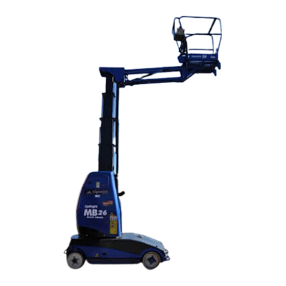
    ICHERHEITSPRÜFUNG Abbildung 2: Arbeitsplattform Hubeinheit Steuerung der Plattform Sicherungsstange Plattform Bedienelemente für das Chassis Chassis W A R N U N G Verwenden Sie die Arbeitsplattform NICHT ohne installierte Sicherungsstange. Auch das Sicherheitsgeschirr muss stets angelegt sein. 3. S ICHERHEITSPRÜFUNG Diese Sicherheitsprüfung kann vom Eigentümer unmittelbar vor dem Transport dieser Maschine durchgeführt werden.
  • Seite 36 ICHERHEITSPRÜFUNG 4. Öffnen Sie die Inspektionsluken auf beiden Seiten der oberen Mastabdeckung. Vergewissern Sie sich, dass das Netzanschlusskabel nicht am Batterieladegerät angeschlossen ist. Überprüfen Sie den Elektrolytstand in allen Batteriezellen. Füllen Sie gegebenenfalls destilliertes Wasser nach. 5. Verwenden Sie das automatische Batterieauffüllsystem, um den erforderlichen Elektrolytstand wiederherzustellen.
  • Seite 37 ICHERHEITSPRÜFUNG 6. Überprüfen Sie vor dem Aktivieren der Funktionen, dass die oberen und unteren Not-Aus-Schalter an allen Bedienstationen zurückgezogen sind. Drehen Sie diese gegebenenfalls im Uhrzeigersinn. Aktivieren Sie die folgenden Funktionen von der unteren Bedienstation aus. HINWEIS: Betreten Sie in dieser Phase NICHT die Plattform. 7.
  • Seite 38 ICHERHEITSPRÜFUNG 11. NOTFALLÜBERSTEUERUNG Bitten Sie einen Kollegen, während Sie auf der Plattform stehen, den Neigungsalarmsensor zu kippen. Dieser Sensor befindet sich in der Chassisbasis. Der Alarm ertönt, und alle normalen Funktionen werden unterbrochen. Abbildung 5: Joystick und Neigungssensor Neigungssensor Joystick mit Totmanngriff 12.
  • Seite 39: Obere

    ETÄTIGUNG DER EDIENELEMENTE DER LATTFORM 4. B ETÄTIGUNG DER EDIENELEMENTE DER LATTFORM Das primäre (obere) Bedienfeld ist an der Vorderseite der Plattform befestigt. Es ist mit einem Multifunktions-Joystick ausgestattet, der eine proportionale Betätigung aller Maschinenfunktionen ermöglicht. Hierzu gehören das Anheben oder Absenken des Masts, das Anheben oder Absenken des Auslegers, das Drehen der Masteinheit sowie das Fahren und Lenken der Maschine.
  • Seite 40: Steuerfunktionen

    ETÄTIGUNG DER EDIENELEMENTE DER LATTFORM TEUERFUNKTIONEN LEMENT EZEICHNUNG UNKTION Die richtige Bewegungsrichtung entnehmen Sie bitte den aufgeklebten Logikdiagrammen. Joystick Bei Auswahl von "Drive" (Antrieb) bewegt sich die Maschine beispielsweise in Vorwärtsrichtung, wenn der Joystick nach vorne gedrückt wird. Der "Totmannschalter" am Joystick muss festgehalten Totmanngriff werden, damit sich die Funktionen aktivieren lassen.
  • Seite 41: Untere Bedienkonsole

    ETÄTIGUNG DER EDIENELEMENTE DER LATTFORM NTERE EDIENKONSOLE LEMENT EZEICHNUNG UNKTION Mit diesem Schalter wird der Wippschalter aktiviert. Aktivierungsschalter Dieser muss während des Betriebs gedrückt gehalten werden. Aktiviert die vorab ausgewählte Funktion in eine der Wippschalter beiden Richtungen. Wahlschalter Mast Dient zur Vorauswahl der Mastfunktion. Wahlschalter Ausleger Dient zur Vorauswahl der Auslegerfunktion.
  • Seite 42: Bedienelemente Und Anzeigen

    ETÄTIGUNG DER EDIENELEMENTE DER LATTFORM EDIENELEMENTE UND NZEIGEN Die Sicherheitsprüfungen vor der Inbetriebnahme müssen vorgenommen werden, bevor die Maschine verwendet wird. Diese Prüfungen sind im vorherigen Abschnitt näher beschrieben. Bediener, die diesen Richtlinien folgen, können sich gleichzeitig mit den Bedienelementen und Anzeigen der Maschine vertraut machen. In diesem Abschnitt sind die Bedienelemente und Anzeigen in Tabellenform aufgeführt und werden anschließend ausführlicher erläutert.
  • Seite 43: Fahren Mit Abgesenkter Arbeitsplattform

    ETÄTIGUNG DER EDIENELEMENTE DER LATTFORM AHREN MIT ABGESENKTER RBEITSPLATTFORM Informationen zu den Bedienelementen und Anzeigen entnehmen Sie bitte den Tabellen 1 und 2. 1. Überprüfen Sie, ob sich die Not-Aus-Schalter der unteren und oberen Bedienkonsolen in der Position ON (EIN) befinden (drehen Sie die Schalter im Uhrzeigersinn, um sie zurückzusetzen).
  • Seite 44: Absenkung Im Notfall ( Von Hand )

    ETÄTIGUNG DER EDIENELEMENTE DER LATTFORM BSENKUNG IM OTFALL V O R S I C H T Während der manuellen Absenkung im Notfall muss äußerst vorsichtig vorgegangen werden, damit gewährleistet ist, dass die Person, die die Absenkung vornimmt, nicht vom Ausleger oder von der Plattform getroffen wird.
  • Seite 45: Ransport

    5. T RANSPORT ASCHINENGEWICHTE Bedenken Sie vor dem Transport oder Anheben der Maschine MB20N/26 deren Gewicht. Es ist wichtig, dass der Schwerpunkt der eingefahrenen Maschine etwa 80 cm über dem Boden und bündig zur Energiekette liegt, die sich an der Rückseite des Masts befindet.
  • Seite 46: Anheben Mit Einem Kran

    RANSPORT 1. Fahren Sie mit einem Gabelstapler niemals von vorne oder hinten an die MB20 heran. 2. Wenden Sie beim Anheben der MB20/26 so früh wie möglich die maximale Gabelstaplerneigung an. 3. Wenn Sie über geneigten oder unebenen Untergrund fahren, wird dringend empfohlen, als Sicherheitsmaßnahme die Auslegermontageeinheit der MB20 am Mast des Gabelstaplers zu befestigen.
  • Seite 47: Transport Mit Einem Lastwagen

    RANSPORT RANSPORT MIT EINEM ASTWAGEN Die MB20/26 kann auf einem dafür ausgelegten Transportfahrzeug oder Anhänger transportiert werden. Dank ihres hohen Steigvermögens kann die Maschine mit eigener Kraft auf eine Standardladerampe gefahren werden (bei einer Neigung von bis zu 14 Grad). Es wird empfohlen, die Maschine auf dem Lastwagen zu wenden, damit sie am Zielort vorwärts von der Rampe gefahren werden kann.
  • Seite 48 RANSPORT Gehen Sie dazu wie folgt vor: Siehe die Zeichnung des Ventilblocks in Abbildung 13. 1. Lassen Sie den Ausleger und die Mastsektionen vollständig ab. Drehen Sie den Mast in die eingefahrene Position. 2. Drehen Sie den Schlüsselschalter im oberen Bedienfeld in die Position OFF (AUS), und ziehen Sie den Schlüssel ab.
  • Seite 49: Rbeiten Nach Dem

    RBEITEN NACH DEM ETRIEB UND VOR DER AGERUNG 6. A RBEITEN NACH DEM ETRIEB UND VOR DER AGERUNG ACH DEM TÄGLICHEN EBRAUCH 1. Vergewissern Sie sich, dass die Plattform (Masten und Ausleger) vollständig abgesenkt ist. 2. Parken Sie die Maschine auf festem und ebenem Untergrund, niemals jedoch auf einer Grasfläche.
  • Seite 50: Batterien

    RBEITEN NACH DEM ETRIEB UND VOR DER AGERUNG ATTERIEN 1. Klemmen Sie die Batterien am Steckverbinder mit Schnellentkupplung ab. Dieser befindet sich im Chassis zwischen der Steuerung und dem Hydrauliktank. 2. Ziehen Sie die Batterieleiter ab, und umwickeln Sie die Leiterklemmen mit Isolierband. Die Batterien halten länger und arbeiten effizienter, wenn sie ständig in Gebrauch sind.
  • Seite 51: Checkliste Für Tägliche Präventive Wartungsarbeiten

    Checkliste für tägliche präventive Wartungsarbeiten HECKLISTE FÜR TÄGLICHE PRÄVENTIVE ARTUNGSARBEITEN Durch täglich durchgeführte präventive Wartungsarbeiten lässt sich übermäßiger Verschleiß vermeiden und die Lebensdauer aller Systeme verlängern. Der Inspektions- und Wartungsplan muss in den angegebenen Intervallen durchgeführt werden. Inspektion und Wartung müssen von Personen ausgeführt werden, die speziell geschult sind und mit Arbeiten an mechanischen und elektrischen Systemen vertraut sind.
  • Seite 52: Echnische Daten

    ECHNISCHE ATEN ECHNISCHE ATEN MB20 MB20 MB20 ARAMETER EU-A US-A USFÜHRUNG USFÜHRUNG 45 %, Zyklus mit über 35 %, Zyklus mit über Auslastung 8 Stunden 8 Stunden Plattformgröße 780 mm x 745 mm 787 mm x 736 mm Maximale Plattformkapazität 215 kg 192 kg Maximale Anzahl Personen...
  • Seite 53 ECHNISCHE ATEN ECHNISCHE ATEN MB26 MB26 EU-A MB26 US-A ARAMETER USFÜHRUNG USFÜHRUNG 45 %, Zyklus mit über 35 %, Zyklus mit über Auslastung 8 Stunden 8 Stunden Plattformgröße 780 mm x 745 mm 787 mm x 736 mm Maximale Plattformkapazität 215 kg 192 kg Maximale Anzahl Personen...
  • Seite 54 NOTES :...
  • Seite 55: Plaque D'identification

    NUMEROS de MODELE et de SERIE figurant sur la plaque d'identification de l'équipement. La plate-forme de travail MB20N/26 a des caractéristiques qui dépassent les exigences des normes : prEn280:2001 et ANSI A92.5 (1999)
  • Seite 56 NOTES:...
  • Seite 57: Règles De Sécurité

    AVERTISSEMENT Tout le personnel devra lire soigneusement, comprendre et respecter toutes les règles de sécurité et instructions d'utilisation avant d'utiliser ou d'effectuer des travaux de maintenance sur une plate-forme de travail aérien UpRight. Règles de sécurité Risque d' lectrocution Risque de basculement...
  • Seite 58: Mb20 Nmb26

    Table des matières ABLE DES MATIÈRES UMÉRO DE PAGE 1. I NTRODUCTION Figure 1. Informations concernant le rangement du manuel NFORMATION PARTICULIÈRE IMITATIONS PARTICULIÈRES ORCE MANUELLE APACITÉ DE LA PLATE FORME CHELLE DE EAUFORT 2. D ESCRIPTION GÉNÉRALE Figure 2. Plate-forme de travail 3.
  • Seite 59: Introduction

    Ce manuel de fonctionnement comporte des instructions et des illustrations qui permettent une utilisation et un fonctionnement sans danger de la plate-forme de travail MB20N & MB26 fabriquée par la Société Upright Powered Access Ltd. Figure 1 : Informations concernant le rangement du manuel Le manuel doit IMPERATIVEMENT être rangé...
  • Seite 60: Capacité De La Plate - Forme

    ESCRIPTION GÉNÉRALE APACITÉ DE LA PLATE FORME La plate-forme est conçue pour des déplacements avec une charge de travail sûre (CTS), comprenant les outils de travail, limitée à 215 kg (475 lbs) maximum. CHELLE DE EAUFORT Ne jamais faire fonctionner l'engin quand la vitesse du vent dépasse 12,5 m/s (28 m.p.h.) [Force 6 sur l'échelle de Beaufort].
  • Seite 61: Contrôle De Sécurité

    ONTRÔLE DE SÉCURITÉ Figure 2 : Plate-forme de travail Ensemble de levage Commande de la plate-forme Barre de sécurité Plate-forme Commandes du châssis Châssis ATTENTION DANGER NE PAS utiliser la plate-forme sans que la barre de sécurité ne soit en place et sans porter le harnais de sécurité.
  • Seite 62 ONTRÔLE DE SÉCURITÉ 4. Ouvrir les panneaux de contrôle des deux côtés du cache de mât supérieur. Vérifier que le câble de secteur c.a.est débranché du chargeur de batterie. Vérifier le niveau d'électrolyte dans chaque élément d'accumulateur. Compléter le niveau si nécessaire en utilisant exclusivement de l'eau distillée 5.
  • Seite 63 ONTRÔLE DE SÉCURITÉ 6. Avant d'utiliser les fonctions, vérifier que les boutons d'arrêt d'urgence supérieur et inférieur de chaque station de commande sont rentrés ; les faire tourner dans le sens horaire si nécessaire. Effectuer l'opération qui suit à partir de la station de commande inférieure.
  • Seite 64 ONTRÔLE DE SÉCURITÉ 11. DESACTIVATION D'URGENCE Etant sur la plate-forme, demander à un collègue de braquer le corps du détecteur de l'alarme d'inclinaison. Ce détecteur est situé à la base du châssis. L'alarme retentira et toutes les fonctions normales seront interrompues. Figure 5 : Levier de commande et détecteur d'inclinaison Détecteur d'inclinaison Levier de commande...
  • Seite 65: Fonctionnement Des Commandes De La Plate

    ONCTIONNEMENT DES COMMANDES DE LA PLATE FORME 4. F ONCTIONNEMENT DES COMMANDES DE LA PLATE FORME Le boîtier de commande primaire (supérieur) est fixé en permanence à l'avant de la plate-forme. Il comporte un levier de commande multi-usages qui permet une commande proportionnelle pour toutes les fonctions de l'engin.
  • Seite 66: Fonctions De Commande

    ONCTIONNEMENT DES COMMANDES DE LA PLATE FORME ONCTIONS DE COMMANDE EPÈRES ÉSIGNATION ONCTION Voir les décalcomanies représentant les schémas logiques pour le sens correct des mouvements. Levier de commande P. ex. : Si Conduite a été présélectionné - un déplacement vers l'avant fait avancer l'engin. L'interrupteur de la poignée "homme mort"...
  • Seite 67: Panneau De Commande Inférieur

    ONCTIONNEMENT DES COMMANDES DE LA PLATE FORME ANNEAU DE COMMANDE INFÉRIEUR EPÈRES ÉSIGNATION ONCTION Ce bouton active le basculeur et doit être maintenu en Bouton d'activation position basse pendant l'opération Active l'opération présélectionnée, dans un sens ou un Basculeur autre Bouton de sélection mât Présélectionne la fonction mât.
  • Seite 68: Commandes Et Voyants

    ONCTIONNEMENT DES COMMANDES DE LA PLATE FORME OMMANDES ET VOYANTS Les contrôles de sécurité pré-utilisation doivent être effectués avant l'utilisation. Ces contrôles sont décrits en détails dans la section précédente. Les utilisateurs qui suivent ces directives se familiariseront avec les commandes et les voyants de l'engin. Cette section présente les commandes et les voyants dans un tableau et fournit des informations plus détaillées.
  • Seite 69: Déplacement Plate - Forme De Travail Abaissée

    ONCTIONNEMENT DES COMMANDES DE LA PLATE FORME ÉPLACEMENT PLATE FORME DE TRAVAIL ABAISSÉE Voir les Tableaux 1 & 2 pour les commandes et les voyants. 1. Vérifier que les boutons d'arrêt d'urgence des consoles de commande inférieure et supérieure sont tous deux en position "ON" (les tourner dans le sens horaire pour les réactiver).
  • Seite 70: Abaissement En Mode Secours

    ONCTIONNEMENT DES COMMANDES DE LA PLATE FORME BAISSEMENT EN MODE SECOURS À LA MAIN A T T E N T I O N Au cours de l'abaissement manuel de secours, on devra faire preuve d'une extrême prudence pour éviter que la personne qui exécute la tâche ne soit frappée par le bras ou la structure de la plate-forme.
  • Seite 71: Transport

    OIDS DE L ENGIN Avant de transporter ou de soulever le MB20N/26, il est nécessaire de connaître son poids. Il est très important de savoir que le centre de gravité de l'engin replié est à environ 80 cm au-dessus du sol, dans le plan de la chaîne d'entraînement qui est située à...
  • Seite 72: Levage Par Grue

    RANSPORT 1. Ne jamais s'approcher du MB20 par l'avant ou par l'arrière lors du levage par chariot- élévateur. 2. Incliner la fourche au maximum dès que possible pendant le levage du MB20/26. 3. Si le déplacement se fait sur un sol en pente ou irrégulier, il est fortement recommandé de fixer provisoirement la structure de montage du bras au mât du chariot-élévateur par mesure de précaution.
  • Seite 73: Transport Par Camion

    RANSPORT RANSPORT PAR CAMION Le MB20/26 peut être porté par un véhicule ou une remorque de transport présentant les caractéristiques voulues. Du fait de sa capacité à monter des pentes fortement inclinées, l'engin peut être acheminé en utilisant son énergie propre jusqu'à une rampe de chargement standard (jusqu'à...
  • Seite 74 RANSPORT Procéder comme suit : Voir le schéma représentant le bloc valves, Figure 13. 1. Abaisser totalement la poutre du bras et les sections du mât. Faire pivoter le mât jusqu'à ce qu'il soit en position repliée. 2. Mettre le boîtier de commande supérieur sur arrêt ("OFF") et retirer la clé. 3.
  • Seite 75: Après Utilisation & Stockage

    & PRÈS UTILISATION STOCKAGE 6. A & PRÈS UTILISATION STOCKAGE PRÈS UTILISATION CHAQUE JOUR 1. Veiller à ce que la plate-forme (mâts et bras) soit complètement abaissée. 2. Garer l'engin sur un sol ferme et plat, jamais sur l'herbe. 3. Mettre la clé sur "arrêt" (OFF) et la retirer. 4.
  • Seite 76: Batteries

    & PRÈS UTILISATION STOCKAGE ATTERIES 1. Couper les batteries au niveau de la prise à débranchement rapide. Elle est située dans le châssis entre le poste de commande et le réservoir hydraulique. 2. Débrancher les fils des batteries et envelopper les cosses de ruban afin d'en assurer l'isolation.
  • Seite 77: Liste De Contrôle De Maintenance Quotidienne

    Liste de contrôle de maintenance préventive quotidienne ISTE DE CONTRÔLE DE MAINTENANCE PRÉVENTIVE QUOTIDIENNE La maintenance préventive quotidienne prévient l'usure anormale et prolonge la durée de vie de tous les systèmes. Le programme d'inspection et de maintenance doit être suivi en respectant les intervalles spécifiés. L'inspection et la maintenance doivent être effectuées par un personnel formé...
  • Seite 78: Spécifications

    PÉCIFICATIONS PÉCIFICATIONS MB20 MB20 MB20 ARAMÈTRE VERSION VERSION Cycle d'utilisation 45% sur un cycle de 8 heures 35% sur un cycle de 8 heures Dimensions de la plate-forme 780 mm x 745 mm 31 in. x 29 in. Capacité maximale de la plate-forme 215 kg.
  • Seite 79 PÉCIFICATIONS PÉCIFICATIONS MB26 MB26, MB26, ARAMÈTRE VERSION VERSION Cycle d'utilisation 45% sur un cycle de 8 heures 35% sur un cycle de 8 heures Dimensions de la plate-forme 780 mm x 745 mm 31 in. x 29 in. Capacité maximale de la plate-forme 215 kg.
  • Seite 80 NOTAS:...
  • Seite 81: Placa De Identificación

    PARTE DELANTERA del chasis Cuando se ponga en contacto con UpRight para solicitar asistencia o información sobre repuestos, incluya siempre el MODELO y los NÚMEROS DE SERIE que figuran en la placa de identificación del equipo.
  • Seite 82 NOTAS:...
  • Seite 83: Reglas De Seguridad

    ADVERTENCIA El personal debe leer atentamente, comprender y respetar todas las reglas de seguridad e instrucciones de funcionamiento antes de utilizar o realizar operaciones de mantenimiento en cualquier plataforma aérea de trabajo de UpRight. Reglas de seguridad Riesgo de electrocución Riesgo de volcado Riesgo de colisión...
  • Seite 84: Mb20 Nmb26

    Contents ONTENIDO ÚMERO DE PÁGINA 1. I NTRODUCCIÓN Figura 1. Información sobre la conservación del manual 1 NFORMACIÓN ESPECIAL IMITACIONES ESPECIALES UERZA MANUAL APACIDAD DE LA PLATAFORMA SCALA DE EAUFORT 2. D ESCRIPCIÓN GENERAL Figura 2. Plataforma de trabajo 3. I NSPECCIÓN DE SEGURIDAD Figura 3.
  • Seite 85: Introducción

    Este manual de funcionamiento está diseñado para proporcionar instrucciones e ilustraciones para un uso y un funcionamiento seguros de la plataforma de trabajo MB20N & MB26 fabricada por Upright Powered Access Ltd. Figura 1: Información sobre la conservación del manual...
  • Seite 86: Capacidad De La Plataforma

    ESCRIPCIÓN GENERAL APACIDAD DE LA PLATAFORMA La plataforma está diseñada para maniobrar con una carga de trabajo segura, incluidas las herramientas de trabajo, hasta un máximo de 215 kg. SCALA DE EAUFORT Nunca utilice la máquina cuando la velocidad del viento supere los 12,5 m/s [6 en la escala de Beaufort].
  • Seite 87: Inspección De Seguridad

    NSPECCIÓN DE SEGURIDAD Figura 2: Plataforma de trabajo Conjunto de elevación Controlador de la plataforma Barra anticaída de seguridad Plataforma Controles del chasis Chasis ADVERTENCIA NO utilice la plataforma de trabajo sin fijar la barra anticaída de seguridad. El arnés de seguridad deberá estar correctamente colocado.
  • Seite 88 NSPECCIÓN DE SEGURIDAD 4. Abra las escotillas de inspección a ambos lados de la cubierta superior del mástil. Compruebe que el cable de alimentación CA está desconectado del cargador de la batería. Compruebe el nivel de electrolito en cada una de las celdas de la batería. Si es necesario, rellene utilizando únicamente agua destilada.
  • Seite 89 NSPECCIÓN DE SEGURIDAD 6. Antes de realizar cualquier operación, compruebe que los botones superior e inferior de parada de emergencia de cada centro de mando están en posición retraída; girar en el sentido de las agujas del reloj si es necesario. Realice la siguiente operación desde el centro de mando inferior.
  • Seite 90 NSPECCIÓN DE SEGURIDAD 11. CONTROL DE EMERGENCIA Mientras se encuentre en la plataforma, pida a un compañero que desvíe el sensor de la alarma de inclinación. Este sensor se encuentra en la base del chasis. La alarma sonará y todas las funciones normales se interrumpirán.
  • Seite 91: Funcionamiento De Los Controles De La Plataforma

    UNCIONAMIENTO DE LOS CONTROLES DE LA PLATAFORMA 4. F UNCIONAMIENTO DE LOS CONTROLES DE LA PLATAFORMA La caja de control principal (superior) está permanentemente fijada a la parte delantera de la plataforma. Dicha caja incluye una palanca de mando multiusos que permite un control proporcional de todas las funciones de la máquina.
  • Seite 92: Funciones De Control

    UNCIONAMIENTO DE LOS CONTROLES DE LA PLATAFORMA UNCIONES DE CONTROL LEMENTOS OMBRES UNCIÓN Consulte los esquema lógicos adhesivos para realizar los movimientos adecuados. Palanca de mando p. ej. si se preselecciona la opción Conducción - al empujar la palanca hacia delante, la máquina se mueve hacia delante.
  • Seite 93: Panel De Control Inferior

    UNCIONAMIENTO DE LOS CONTROLES DE LA PLATAFORMA ANEL DE CONTROL INFERIOR LEMENTOS OMBRES UNCIÓN Este botón activa el interruptor basculante, y debe Botón Habilitar mantenerse presionado durante el funcionamiento de la máquina. Interruptor basculante Activa la función preseleccionada en cualquier dirección Botón de selección de mástil Preselecciona la función mástil.
  • Seite 94: Controles E Indicadores

    UNCIONAMIENTO DE LOS CONTROLES DE LA PLATAFORMA ONTROLES E INDICADORES Las comprobaciones de seguridad previas al funcionamiento deben realizarse antes de poner la máquina en funcionamiento. Estas comprobaciones están detalladas en el apartado anterior. Los operarios que sigan estas directrices se familiarizarán con los controles e indicadores de la máquina.
  • Seite 95: Maniobra Con La Plataforma De Trabajo Elevada

    UNCIONAMIENTO DE LOS CONTROLES DE LA PLATAFORMA ANIOBRA CON LA PLATAFORMA DE TRABAJO DESCENDIDA Consulte las tablas 1 y 2 para ver los controles e indicadores. 1. Compruebe que los dos botones de parada e emergencia de las consolas de control inferior y superior se encuentran en posición "ON"...
  • Seite 96: Descenso De Emergencia

    UNCIONAMIENTO DE LOS CONTROLES DE LA PLATAFORMA ESCENSO DE EMERGENCIA MANUAL PRECAUCIÓN Durante el descenso de emergencia manual, deben extremarse las precauciones para garantizar que la persona que realiza la tarea no recibe golpes del aguilón o de la estructura de la plataforma.
  • Seite 97: Transporte

    RANSPORTE ESOS DE LA MÁQUINA Antes de transportar o elevar los modelos MB20N/26 averigüe su peso. Es muy importante darse cuenta de que el centro de gravedad de la máquina entibada se encuentra aproximadamente a 80 cm del suelo y en el plano de la cadena de energía situada en la parte trasera del mástil.
  • Seite 98: Elevación Con Grúa

    RANSPORTE 1. Nunca se acerque al modelo MB20 desde la parte delantera o trasera mientras realiza una elevación con la horquilla. 2. Utilice la máxima inclinación de la horquilla elevadora lo antes posible cuando eleve los modelos MB20/26. 3. Si maniobra sobre terreno inclinado o desnivelado, se recomienda encarecidamente que ate temporalmente la estructura de soporte del aguilón del modelo MB20 al mástil de la horquilla elevadora como precaución de seguridad.
  • Seite 99: Transporte Por Camión

    RANSPORTE RANSPORTE POR CAMIÓN Los modelos MB20/26 pueden transportarse en un vehículo de transporte apropiado o remolque. Debido a su elevado acceso en pendiente, la máquina puede desplazarse por debajo de su propia potencia en una rampa de carga estándar (hasta 14 grados). Se recomienda introducir la máquina en el camión marcha atrás para que se desplace hacia abajo en el lugar de entrega.
  • Seite 100 RANSPORTE Proceda como sigue: Consulte el dibujo del bloqueo de la válvula en la Figura 13. 1. Descienda totalmente la pluma del aguilón y las secciones del mástil. Gire el mástil hasta su posición estibada. 2. Gire la caja de control superior hasta la posición OFF y extraiga la llave. 3.
  • Seite 101: Después Del Uso Y Almacenamiento

    ESPUÉS DEL USO Y ALMACENAMIENTO 6. D ESPUÉS DEL USO Y ALMACENAMIENTO ESPUÉS DEL USO DIARIO 1. Asegúrese de que la plataforma (mástiles y aguilón) se encuentra totalmente descendida. 2. Aparque la máquina en terreno firme y nivelado, nunca sobre hierba. 3.
  • Seite 102: Baterías

    ESPUÉS DEL USO Y ALMACENAMIENTO ATERÍAS 1. Desconecte las baterías en la toma del enchufe de conexión rápida. Dicha toma se encuentra en el chasis, entre el controlador y el tanque hidráulico. 2. Desconecte los cables de la batería y proteja con cinta aislante los terminales para garantizar el aislamiento.
  • Seite 103: Lista De Control De Mantenimiento Diario

    Lista de control de mantenimiento preventivo diario ISTA DE CONTROL DE MANTENIMIENTO PREVENTIVO DIARIO El mantenimiento preventivo diario evitará un desgaste anormal y prolongará la vida de todos los sistemas. El plan de inspección y mantenimiento se debe llevar a cabo en los intervalos señalados.
  • Seite 104: Especificaciones

    SPECIFICACIONES SPECIFICACIONES MB20 MB20 ERSIÓN MB20 ARÁMETRO ERSIÓN EE.UU. Ciclo de funcionamiento 45% en un ciclo de 8 horas 35% en un ciclo de 8 horas Tamaño de la plataforma 780 mm x 745 mm 31 in. x 29 in. Capacidad máxima de la plataforma 215 kg.
  • Seite 105 SPECIFICACIONES SPECIFICACIONES MB26 MB26 UE MB26 EE.UU. ARÁMETRO ERSIÓN ERSIÓN Ciclo de funcionamiento 45% en un ciclo de 8 horas 35% en un ciclo de 8 horas Tamaño de la plataforma 780 mm x 745 mm 31in. x 29 in. Capacidad máxima de la plataforma 215 kg.
  • Seite 106 NOTE:...
  • Seite 107: Targhetta Identificativa

    La targhetta identificativa della piattaforma di lavoro si trova all'esterno nella parte ANTERIORE del telaio. Quando si contatta UpRight per una richiesta d'assistenza o per informazioni relative ai componenti, accertarsi di includere i NUMERI DEL MODELLO E DI SERIE desunti dalla targhetta identificativa dell'attrezzatura.
  • Seite 108 NOTE:...
  • Seite 109: Norme Di Sicurezza

    Tutto il personale deve leggere, comprendere e rispettare tutte le norme di sicurezza, le istruzioni d'uso e le istruzioni/i requisiti nazionali di sicurezza prima di utilizzare qualsiasi piattaforma di lavoro aerea UpRight o di eseguire interventi di manutenzione. Norme di sicurezza...
  • Seite 110: Mb20 Nmb26

    Indice NDICE UMERO PAGINA 1. I NTRODUZIONE Figura 1. Informazioni relative alla conservazione del manuale NFORMAZIONI SPECIALI IMITAZIONI SPECIALI ORZA MANUALE APACITÀ PIATTAFORMA CALA DI EAUFORT 2. D ESCRIZIONE GENERALE Figura 2. Piattaforma di lavoro 3. I SPEZIONE DI SICUREZZA Figura 3.
  • Seite 111 Questo manuale d'istruzioni ha lo scopo di fornire istruzioni e immagini per l'uso sicuro e la messa in funzione della Piattaforma di Lavoro MB20N & MB26 realizzata da Upright Powered Access Ltd. Figura 1: Informazioni relative alla conservazione del Manuale...
  • Seite 112: Descrizione Generale

    ESCRIZIONE GENERALE APACITÀ PIATTAFORMA La Piattaforma è stata progettata per lavorare con un carico di lavoro sicuro (SWL) ivi inclusi gli attrezzi di lavoro ad un limite massimo di 215 kg (475 lbs). CALA DI EAUFORT Per nessun motivo mettere in funzione la macchina quando le intensità del vento superano i 12,5 m/s (28 m.p.h.) [Scala di Beaufort 6].
  • Seite 113 SPEZIONE DI SICUREZZA Figura 2: Piattaforma di lavoro Dispositivo di elevazione Controller piattaforma Sbarra di messa a terra di sicurezza Piattaforma Comandi carrello Carrello A V V E R T I M E N T O NON utilizzare la piattaforma di lavoro senza aver posizionato la sbarra di messa a terra di sicurezza e senza l'imbracatura di sicurezza.
  • Seite 114 SPEZIONE DI SICUREZZA 4. Aprire i portelli d'Ispezione su entrambi i lati della copertura del montante superiore. Verificare che il cavo della rete AC sia scollegato dal caricabatteria. Verificare il livello dell'elettrolito in ciascun elemento di batteria di accumulatori. Rabboccare a secondo delle necessità...
  • Seite 115 SPEZIONE DI SICUREZZA 6. Previamente all'attivazione di qualsiasi funzione, accertarsi che i pulsanti per l'arresto d'emergenza superiore e inferiore su ciascuna stazione di controllo siano retratti; ruotare in senso orario se necessario. Eseguire la seguente operazione dalla Stazione di controllo inferiore. NOTA: NON entrare nella piattaforma durante questa fase.
  • Seite 116 SPEZIONE DI SICUREZZA 11. OVER-RIDE D'EMERGENZA Mentre ci si trova all'interno della piattaforma, chiedere ad un collega di deflettere il corpo del sensore dell'allarme d'inclinazione. Questo sensore è posizionato sulla base del telaio. L'allarme inizierà a suonare e tutte le normali funzioni saranno interrotte.
  • Seite 117 UNZIONAMENTO DEI COMANDI DELLA PIATTAFORMA 4. F UNZIONAMENTO DEI COMANDI DELLA PIATTAFORMA Il terminale di comando principale (Superiore) è fissato in modo permanente alla parte anteriore della piattaforma. Esso è caratterizzato da una leva di comando a cloche multiuso che consente l'attivazione proporzionale di tutte le funzioni della macchina. Ciò...
  • Seite 118: Funzioni Di Controllo

    UNZIONAMENTO DEI COMANDI DELLA PIATTAFORMA UNZIONI DI CONTROLLO UNZIONE Fare riferimento ai diagrammi logici decal. per la direzione corretta del movimento. Leva di comando a cloche ad es. Se Azionamento è preselezionato - la spinta in avanti consente alla macchina di spostarsi in avanti. L'interruttore della leva di "arresto automatico"...
  • Seite 119 UNZIONAMENTO DEI COMANDI DELLA PIATTAFORMA ANNELLO DI CONTROLLO INFERIORE UNZIONE Questo pulsante abilita l'Interruttore del bilanciere e Pulsante di avvio deve essere premuto durante il funzionamento Attiva l'operazione preselezionata in entrambe le Interruttore bilanciere direzioni Pulsante di selezione montante Preseleziona la funzione Montante. Pulsante di selezione braccio Preseleziona la funzione Braccio.
  • Seite 120: Comandi E Indicatori

    UNZIONAMENTO DEI COMANDI DELLA PIATTAFORMA OMANDI E INDICATORI I controlli relativi alla sicurezza prefunzionamento devono essere portati a termine previamente alla messa in funzione della macchina. Questi controlli sono stati descritti dettagliatamente nella precedente sezione. Gli operatori che seguono scrupolosamente queste linee guida prenderanno familiarità con i comandi e gli indicatori situati sulla macchina.
  • Seite 121 UNZIONAMENTO DEI COMANDI DELLA PIATTAFORMA ARCIA CON LA PIATTAFORMA DI LAVORO ABBASSATA Fare riferimento alle Tabelle 1 & 2 per i comandi e gli indicatori. 1. Verificare che il pulsante di Arresto d'emergenza della console di controllo superiore e inferiore si trovi in posizione "ON" (ruotare in senso orario per resettare). 2.
  • Seite 122 UNZIONAMENTO DEI COMANDI DELLA PIATTAFORMA BBASSAMENTO DI EMERGENZA MANUALE A T T E N Z I O N E Durante l'abbassamento d'emergenza manuale, deve essere prestata la massima attenzione al fine di garantire che le persone che stanno eseguendo l'operazione non vengano colpite dal braccio o dalla struttura della piattaforma.
  • Seite 123 RASPORTO ESO DELLA MACCHINA Prima del trasporto o del sollevamento della macchina MB20N/26 verificare il suo peso. È di fondamentale importanza comprendere che il centro di gravità della macchina assettata si trova approssimativamente a 80 cm sopra il livello del terreno e nel piano di riscontro della catena energetica che si trova sul retro del montante.
  • Seite 124 RASPORTO 1. Non avvicinarsi mai alla MB20 dalla parte anteriore o posteriore durante il sollevamento della forca. 2. Utilizzare l'inclinazione massima del carrello elevatore a forca il prima possibile durante il sollevamento del MB20/26. 3. Se si sta marciando su un terreno in pendenza o scosceso si raccomanda vivamente di legare temporaneamente la struttura di sostegno del braccio MB20 al montante del carrello elevatore a forca come precauzione si sicurezza.
  • Seite 125 RASPORTO RASPORTO MEDIANTE UTOCARRO L'MB20/26 può essere trasportato su un veicolo di trasporto ritenuto adatto o su di un carrello da rimorchio. A motivo della sua pendenza massima superabile, la macchina può essere condotta su una rampa di carico standard (fino a 14 gradi). Si raccomanda di posizionare la macchina verso l'alto sul camion in modo tale da consentirne il trasporto al di sotto della rampa presso il punto di consegna.
  • Seite 126 RASPORTO Procedere nel modo seguente: Fare riferimento alla Figura 13 che mostra lo schema di blocco della valvola. 1. Abbassare completamente l'asta di fiocco e le sezioni del montante. Ruotare il montante nella posizione di riposo. 2. Ruotare il Terminale di controllo superiore in posizione OFF e rimuovere la chiave. 3.
  • Seite 127 & M OPO L AGAZZINAGGIO 6. D & M OPO L AGAZZINAGGIO OPO L USO QUOTIDIANO 1. Accertarsi che la piattaforma (montanti e braccio) siano completamente abbassati. 2. Parcheggiare la macchina su di un terreno piano e stabile, non su una superficie scivolosa.
  • Seite 128 & M OPO L AGAZZINAGGIO ATTERIE 1. Scollegare le batterie dall'interruttore di connessione rapida e dalla presa. Esse si trovano all'interno del telaio tra il controller ed il serbatoio idraulico. 2. Scollegare i connettori della batteria e fasciare con nastro isolante i morsetti di connessione per garantirne l'isolamento.
  • Seite 129 HECKLIST ANUTENZIONE PREVENTIVA QUOTIDIANA HECKLIST ANUTENZIONE PREVENTIVA QUOTIDIANA La Manutenzione preventiva quotidiana potrà prevenire l'usura anomala e prolungherà il ciclo di vita utile di tutti i sistemi. Il programma di ispezione e manutenzione deve essere condotto ad intervalli regolari e specificati. L'ispezione e la manutenzione devono essere eseguite da personale che ha ricevuto un adeguato addestramento e che ha familiarità...
  • Seite 130 PECIFICHE PECIFICHE MB20 MB20 MB20 ARAMETRO ERSIONE ERSIONE Ciclo rendimento lavoro 45% ciclo di 8 ore 35% ciclo di 8 ore Dimensione piattaforma 780 mm x 745 mm 31 in. x 29 in. Capacità massima piattaforma 215 kg. 425 lbs. Numero massimo di persone Altezze: Altezza massima piattaforma...
  • Seite 131 PECIFICHE PECIFICHE MB26 MB26 V MB26 V ARAMETRO ERSIONE ERSIONE Ciclo rendimento lavoro 45% ciclo di 8 ore 35% ciclo di 8 ore Dimensione piattaforma 780 mm x 745 mm 31 in. x 29 in. Capacità massima piattaforma 215 kg. 425 lbs.
  • Seite 132 Local Distributor: Lokaler Vertiebshändler: Distributeur local: El Distribuidor local: Il Distributore locale: Europe TEL: +1 (559) 443 6600 TEL: +44 (0) 845 1550 058 FAX: +1 (559) 268 2433 FAX: +44 (0) 195 2299 948 www.upright.com pn - 501375-001...

Diese Anleitung auch für:

501375-001Mb20n-132Mb26-245

Inhaltsverzeichnis