Herunterladen Inhalt Inhalt Diese Seite drucken
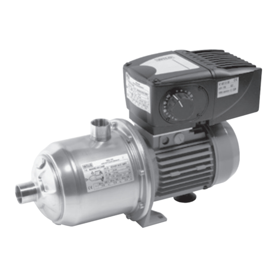
Wilo Economy MHIE 1-Serie Einbau- Und Betriebsanleitung

Wilo Economy MHIE 1-Serie Einbau- Und Betriebsanleitung

Vorschau ausblenden Andere Handbücher für Economy MHIE 1-Serie:
Inhaltsverzeichnis

Werbung

Verfügbare Sprachen
  • DE

Verfügbare Sprachen

  • DEUTSCH, seite 1
Pioneering for You
Wilo-Economy MHIE 1~
de Einbau- und Betriebsanleitung
en Installation and operating instructions
fr
Notice de montage et de mise en service
nl
Inbouw- en bedieningsvoorschriften
4 090 996-Ed.07 / 2021-09-Wilo
es
Instrucciones de instalación y funcionamiento
it
Istruzioni di montaggio, uso e manutenzione
pt
Manual de Instalação e funcionamento
ru Инструкция по монтажу и эксплуатации

Werbung

Inhaltsverzeichnis
loading

Inhaltszusammenfassung für Wilo Economy MHIE 1-Serie

  • Seite 1 Instrucciones de instalación y funcionamiento en Installation and operating instructions Istruzioni di montaggio, uso e manutenzione Notice de montage et de mise en service Manual de Instalação e funcionamento Inbouw- en bedieningsvoorschriften ru Инструкция по монтажу и эксплуатации 4 090 996-Ed.07 / 2021-09-Wilo...
  • Seite 2 Fig. 1: Fig. 2: or/ou or/ou Fig. 5: Fig. 3: Fig. 4: Not used...
  • Seite 3 Fig. 6: Fig. 7: or/ou Fig. 8: or/ou...
  • Seite 4 Fig. 9: Fig. 10:...
  • Seite 5: Inhaltsverzeichnis

    Einbau- und Betriebsanleitung Installation and operating instructions Notice de montage et de mise en service Inbouw- en bedieningsvoorschriften Instrucciones de instalación y funcionamiento Istruzioni di montaggio, uso e manutenzione Manual de instalação e funcionamento Инструкция по монтажу и эксплуатации...
  • Seite 7: Allgemeines

    Die Pumpe darf auf keinen Fall am ACHTUNG! Frequenzumformer angehoben werden. 2.3 Gefahren bei Nichtbeachtung der Sicherheitshinweise Die Nichtbeachtung der Sicherheitshinweise kann eine Gefährdung von Personen und Pumpe/Anlage zur Folge haben. Die Nichtbeachtung der Sicher- Einbau- und Betriebsanleitung - Wilo-Economy MHIE 1~...
  • Seite 8: Produkte Und Zubehör

    (2 %) verlegen (siehe Fig. 1). - Bei starren Rohrleitungen darauf achten, dass das Gewicht der Leitungen nicht allein von der Pumpe getragen wird. Stützen bzw. Rohrhalterungen ein- setzen (siehe Fig. 1 + 2, Pos. 7). WILO SE 09/2021...
  • Seite 9: Elektrische Anschlüsse

    Ist-Vergleich der aktuellen und gespeicherten Daten wird ein stetiger Schutz des Motors und der Pumpe gewährleistet. Bei einem zu hohen Widerstand des Neutralleiters muss vor dem Motor-Frequenzumformer eine entsprechende Schutzvorrichtung eingebaut wer- den. Einbau- und Betriebsanleitung - Wilo-Economy MHIE 1~...
  • Seite 10: Netzanschluss

    (Phase + Neutral+ Erde). Abb. 3b, réf. 20 Anschluss der Ein-/Ausgänge Anschlussklemmen Ein-/Ausgänge 41/42: Fehlerbericht (potenzialfreier Kontakt) 41 42 10V : +10V DC max 5mA 0V : Null volt +24V : +24V DC max; 200mA Abb. 3a 10 11 WILO SE 09/2021...
  • Seite 11 Diese Fernsteuerung ist nicht auf den 9 10 11 Auslieferungszustand eingestellt (Shunt vorhanden). Wenn Sie die Fernsteuerung verwenden wollen, entfer- nen Sie den Nebenschluss und ersetzen Sie ihn durch Fernsteuerung einen freien Kontakt. Beispiel: Schwimmerschalter, Manometer für Trockenlauf... Einbau- und Betriebsanleitung - Wilo-Economy MHIE 1~...
  • Seite 12 +24V Drucksensor Potentiometer Externe Kontrolle Isolieren Sie das Ende des Restliches Kabel Drucksensor : 4-20mA 9 10 11 Sollwert durch externe Steuerung 0-10V 0-20mA 4-20mA +24V Drucksensor Potentiometer Externe Kontrolle Isolieren Sie das Ende des Restliches Kabel WILO SE 09/2021...
  • Seite 13 9 10 11 0-20mA Potentiometer Externe Kontrolle Isolieren Sie das Ende des Restliches Kabel Sollwert durch externe Steuerung 0-10V 9 10 11 0-10V Potentiometer Externe Kontrolle Isolieren Sie das Ende des Restliches Kabel Einbau- und Betriebsanleitung - Wilo-Economy MHIE 1~...
  • Seite 14 Externe Steuerung der Frequenz in Modus 3 Externes Signal 0-20 mA Externes Signal 0-10 V Bereich, in dem der Frequenzumformer stoppt. Bereich, in dem der Frequenzumformer stoppt. 100 % 100 % 40 % 40 % Eingangsstromstärke (mA) Eingangsspannung (V) WILO SE 09/2021...
  • Seite 15: Vorbereitende Spülung

    - Pumpe und Ansaugleitung vollständig befüllen, bis Wasser blasenfrei aus der Füllöffnung austritt. - Den Hahn (siehe Fig. 4, Pos. 12) schließen (dieser kann am Rohr bleiben), das Rohr abnehmen und die Einlass-/Entlüftungsschraube wieder ein- schrauben. Einbau- und Betriebsanleitung - Wilo-Economy MHIE 1~...
  • Seite 16: Wartung

    Störung und schließen Sie die Stromversorgung wieder an. Wenn es sich um eine schwere Störung handelt, ist der Einsatz eines Kundendienstmitarbeiters erforderlich. Wenn das Fluid toxisch, korrosiv oder für den Lässt sich die Betriebsstörung nicht beheben, wenden Menschen gefährlich ist, muss WILO oder der Sie sich bitte an Ihren Fachhandwerker oder an den autorisierte Reparaturbetrieb hierüber infor- WILO-Kundendienst in Ihrer Nähe.
  • Seite 17: Die Pumpe Vibriert

    Elektro- und Elektronikprodukte nicht mit dem Hausmüll entsorgt werden dürfen. Für eine ordnungsgemäße Behandlung, Recycling und Entsorgung der betroffenen Altprodukte, folgende Punkte beachten: • Diese Produkte nur bei dafür vorgesehenen, zerti- Einbau- und Betriebsanleitung - Wilo-Economy MHIE 1~...
  • Seite 18: Installation And Operating Instructions

    2.5 Safety instructions for inspection and installa- +40°C (in cases of higher temperatures, please tion work consult Wilo after-sales service) • Sound pressure level 50/60Hz 0/+3 dB(A): 66 It is the responsibility of the operator to ensure that all inspection and installation work is carried...
  • Seite 19: Accessories (Optional)

    - In the case of rigid pipes, take care to ensure that the weight of the lines is not borne by the pump alone. Utilise supports and/or pipe brackets (see Figs. 1 + 2, Pos. 7). Installation and operating instructions - Wilo-Economy MHIE 1~...
  • Seite 20: Electrical Connections

    The frequency converter is equipped with a motor protection feature. Constant protection of the motor and of the pump are ensured by a continu- ous nominal/actual comparison of the current and stored data. In the event of excessively great resistance on WILO SE 09/2021...
  • Seite 21 Terminals for inputs / outputs 41/42 : Failure contact (free contact) 41 42 10V : +10V DC max 5mA 0V : Zero volt +24V : +24V DC max 200mA Fig. 3a 10 11 Installation and operating instructions - Wilo-Economy MHIE 1~...
  • Seite 22 This remote control isn’t set at the state of delivery 9 10 11 (shunt present). If you want use the remote control, remove the shunt and replace it by a free contact Remote control Example: Float switch, pressure gauge for dry-running… WILO SE 09/2021...
  • Seite 23 Insulate the end of the remaining wire Sensor : 4-20mA 9 10 11 Set value by external control 0-10V 0-20mA 4-20mA +24V Sensor Potentiometer External control Insulate the end of the remaining wire Installation and operating instructions - Wilo-Economy MHIE 1~...
  • Seite 24 Mode 3 External control 0-20mA 9 10 11 0-20mA Potentiometer External control Insulate the end of the remaining wire External control 0-10V 9 10 11 0-10V Potentiometer External control Insulate the end of the remaining wire WILO SE 09/2021...
  • Seite 25 External control of the frequency in Mode 3 External signal 0-20 mA External signal 0-10 V Range in which the frequency converter stops. Range in which the frequency converter stops. 100% 100% Input current level (mA) Input voltage (V) Installation and operating instructions - Wilo-Economy MHIE 1~...
  • Seite 26 - Close the cock (see Fig. 4, Pos. 12) (it can remain mounted on the pipe), remove the pipe and screw Status of the LEDs green LED red LED the inlet/bleeder screw back in. Frequency converter voltage load/pump in operation Frequency converter voltage load/pump in standstill WILO SE 09/2021...
  • Seite 27: Operating Faults

    If a major fault is present, then an after-sales service employee must be called in. If the operating fault cannot be rectified, then please If the fluid is toxic, corrosive or hazardous for contact your local professional tradesmen or the Wilo personnel, then WILO or the authorised repair after-sales service in your vicinity.
  • Seite 28: Spare Parts

    Spare parts must be ordered from the local autho- • Observe the locally applicable regulations! rised dealer and/or from Wilo after-sales service. Please consult your local municipality, the nearest In order to avoid unnecessary inquiries or incor-...
  • Seite 29: Généralités

    Plus précisément, les dangers encourus peuvent être les suivants : • Défaillance de fonctions importantes de la pompe Notice de montage et de mise en service - Wilo-Economy MHIE 1~...
  • Seite 30: Produits Et Accessoires

    - Aucune prise d’air ne doit être tolérée sur la capteur : ≤ 1 % ; utilisation entre 30 % et tuyauterie d’aspiration qui sera en pente montan- 100 % de la plage de lecture) ... te (2 %) (Voir Fig. 1). WILO SE 09/2021...
  • Seite 31: Raccordements Électriques

    La protection électrique des moteurs est intégrée au variateur. Celui-ci est paramètré pour tenir compte des caractéristiques de la pompe et assu- rer sa protection et celle du moteur. Notice de montage et de mise en service - Wilo-Economy MHIE 1~...
  • Seite 32 Branchement des entrées / sorties Borniers des entrées / sorties 41/42 : Report de défaut (contact sec) 41 42 10V : +10V DC max 5mA 0V : Zero volt +24V : +24V DC max 200mA Voir Fig. 3a 10 11 WILO SE 09/2021...
  • Seite 33 Si vous souhaitez configurer cette commande à dis- Commande à distance tance, oter le shunt (8 et 11) et le remplacer par un contact sec. Exemple : Interrupteur à flotteur, pressostat manque d‘eau… Notice de montage et de mise en service - Wilo-Economy MHIE 1~...
  • Seite 34 9 10 11 Commande externe 0-20mA 0-20mA 4-20mA +24V Commande Capteur Potentiomètre externe Isoler l‘extrémité du fil restant Capteur : 4-20mA 9 10 11 Commande externe 0-10V 0-20mA 4-20mA +24V Commande Capteur Potentiomètre externe Isoler l‘extrémité du fil restant WILO SE 09/2021...
  • Seite 35 Commande externe 0-20mA 9 10 11 0-20mA Commande Potentiomètre externe Isoler l‘extrémité du fil restant Commande externe 0-10V 9 10 11 0-10V Commande Potentiomètre externe Isoler l‘extrémité du fil restant Notice de montage et de mise en service - Wilo-Economy MHIE 1~...
  • Seite 36 Commande externe de la fréquence en Mode 3 Signal externe 0-20 mA Signal externe 0-10 V Zone où le variateur s’arrête. Zone où le variateur s’arrête. 100 % 100 % 40 % 40 % Entrée en Courant (mA) Entrée en Tension (V) WILO SE 09/2021...
  • Seite 37 - Fermer le robinet (Voir Fig. 4 - rep. 12) (celui-ci Variateur sous tension/ allumée éteinte peut rester en place), retirer le tuyau et revisser le pompe à l’arrêt bouchon de remplissage. Notice de montage et de mise en service - Wilo-Economy MHIE 1~...
  • Seite 38: Incidents De Fonctionnement

    Si le liquide pompé est toxique, corrosif ou S’il n’est pas possible de remédier au défaut, faire appel dangereux pour l’homme, en informer impérati- à un installateur agréé, au SAV Wilo le plus proche ou à vement le réparateur agréé WILO. Dans ce cas, son représentant.
  • Seite 39 Dans l’Union européenne, ce symbole peut apparaître sur le produit, l’emballage ou les documents d’accompagnement. Il signifie que les produits électriques et électroniques concernés ne doivent pas être éliminés avec les ordures ménagères. Notice de montage et de mise en service - Wilo-Economy MHIE 1~...
  • Seite 40 2.5 Veiligheidsaanwijzingen voor inspectie- en • Omgevingstemperatuur (standaard): montagewerkzaamheden + 40°C (neem bij hogere temperaturen contact op met de Wilo-klantendienst) De gebruiker dient ervoor te zorgen dat alle inspectie- en montagewerkzaamheden worden • Geluidsniveau 50/60Hz 0/+3 dB(A): 66 uitgevoerd door bevoegd en gekwalificeerd vak-...
  • Seite 41: Toebehoren (Optioneel)

    ≤ 1 %; gebruik tussen 30% en 100% van het - Let er bij starre leidingen op dat het gewicht leesbereik). van de leidingen niet alleen door de pomp wordt gedragen. Gebruik steunen resp. buishouders (zie fig. 1 + 2, pos. 7). Inbouw- en bedieningsvoorschriften - Wilo-Economy MHIE 1~...
  • Seite 42: Elektrische Aansluitingen

    Doordat de actuele en opgesla- gen gegevens continu worden vergeleken (inge- steld/werkelijk), is gegarandeerd dat de motor en de pomp steeds beveiligd zijn. Bij een te hoge weerstand van de neutrale gelei- der moet voor de frequentie-omvormer van de WILO SE 09/2021...
  • Seite 43 Fig. 3b, ref. 20 Aansluiten van ingangen/uitgangen Aansluitklemmen ingangen/uitgangen 41/42: Storingsmelding (droog contact) 41 42 10V : +10V DC max 5mA 0V : nul volt +24V : +24V DC max 200mA Fig. 3a 10 11 Inbouw- en bedieningsvoorschriften - Wilo-Economy MHIE 1~...
  • Seite 44 Als u deze afstandsbediening wilt configureren, verwi- jdert u de shunt (zie hieronder). Als u deze afstandsbe- diening wilt configureren, verwijdert u de shunt (8 en 11) en vervangt u deze door een een droog contact. Voorbeeld: Vlotterschakelaar, lage waterdruk schakelaar... WILO SE 09/2021...
  • Seite 45 Druksensor Potentiometer besturing Isoleer het einde van de resterende draad Druksensor : 4-20mA 9 10 11 Externe besturing 0-10V 0-20mA 4-20mA +24V Externe Druksensor Potentiometer besturing Isoleer het einde van de resterende draad Inbouw- en bedieningsvoorschriften - Wilo-Economy MHIE 1~...
  • Seite 46 Modus 3 Externe besturing 0-20mA 9 10 11 0-20mA Externe Potentiometer besturing Isoleer het einde van de resterende draad Externe besturing 0-10V 9 10 11 0-10V Externe Potentiometer besturing Isoleer het einde van de resterende draad WILO SE 09/2021...
  • Seite 47 Ingangsspanning (V) Externe besturing van de frequentie in modus 3 Extern signaal 0-20 mA Extern signaal 0-10 V Bereik waarin de frequentie-omvormer stopt. Bereik waarin de frequentie-omvormer stopt. 100% 100% Ingangsstroomsterkte (mA) Ingangsspanning (V) Inbouw- en bedieningsvoorschriften - Wilo-Economy MHIE 1~...
  • Seite 48: Inbedrijfname

    - Sluit de kraan (zie fig. 4, pos. 12) (deze kan aan Status van de LED’s Groene LED Rode LED de leiding blijven), verwijder de leiding en schroef de inlaat-/ontluchtingsschroef er weer in. Frequentie-omvormer belast met Aan spanning/pomp in bedrijf Frequentie-omvormer belast met Aan spanning/pomp in stilstand WILO SE 09/2021...
  • Seite 49 Als de vloeistof toxisch, corrosief of voor men- Neem contact op met een vakspecialist of met de sen gevaarlijk is, moet WILO of het verantwo- WILO-klantendienst bij u in de buurt als de bedrijfssto- ordelijke reparatiebedrijf hiervan op de hoogte ring niet kan worden verholpen.
  • Seite 50: Reserveonderdelen

    Reserveonderdelen moeten bij een officiële dealer • Neem de lokale voorschriften in acht! en/of bij de Wilo-klantendienst in uw buurt wor- Vraag naar informatie over de correcte afvoer bij den besteld. Geef bij de bestelling alle gegevens...
  • Seite 51: Seguridad

    La tensión de la bomba no debe ser en 2.3 Riesgos en caso de inobservancia de las ins- ¡ATENCIÓN! ningún caso aumentada en el converti- trucciones de seguridad dor de frecuencia. La inobservancia de las indicaciones de seguri- Instrucciones de instalación y funcionamiento - Wilo-Economy MHIE 1~...
  • Seite 52: Accesorios (Opcional)

    - En el caso de tuberías rígidas, tenga en cuenta que el peso de las tuberías no debe ser soportado úni- camente por la bomba. Utilice apoyos o soportes para las tuberías (véanse las fig. 1 + 2, pos. 7). WILO SE 09/2021...
  • Seite 53: Conexiones Eléctricas

    Si el conductor neutro ofrece una resistencia Instrucciones de instalación y funcionamiento - Wilo-Economy MHIE 1~...
  • Seite 54: Alimentación Eléctrica

    Conexión de las entradas y salidas Bornes de conexión de entradas y salidas 41/42 : Reporte de fallas (contacto seco) 41 42 10V : +10V DC max 5mA 0V : Cero volt +24V : +24V DC max 200mA Fig. 3a 10 11 WILO SE 09/2021...
  • Seite 55 Control remoto derivación (8 y 11) y sustitúyala por un contacto seco. Ejemplo: interruptor de flotador, interruptor de baja presión de agua.. Traducción realizada con la versión gratuita del traduc- tor www.DeepL.com/Translator Instrucciones de instalación y funcionamiento - Wilo-Economy MHIE 1~...
  • Seite 56 Mando externo 0-20mA 0-20mA 4-20mA +24V Sensor Potenciómetro Mando externo Aislar el extremo del cable restante Sensor: 4-20mA 9 10 11 Mando externo 0-10V 0-20mA 4-20mA +24V Sensor Potenciómetro Mando externo Aislar el extremo del cable restante WILO SE 09/2021...
  • Seite 57 Mando externo 0-20mA 9 10 11 0-20mA Potenciómetro Mando externo Aislar el extremo del cable restante Mando externo 0-10V 9 10 11 0-10V Potenciómetro Mando externo Aislar el extremo del cable restante Instrucciones de instalación y funcionamiento - Wilo-Economy MHIE 1~...
  • Seite 58 Margen en el que el convertidor de frecuencia Margen en el que el convertidor de frecuencia se detiene. se detiene. 100 % 100 % 40 % 40 % Intensidad de corriente Tensión de entrada (V) de entrada (mA) WILO SE 09/2021...
  • Seite 59 - Cierre el grifo (véase la fig. 4, pos. 12) (éste puede permanecer en la tubería), retire el tubo y vuelva a atornillar el tornillo de llenado/escape de aire. Instrucciones de instalación y funcionamiento - Wilo-Economy MHIE 1~...
  • Seite 60 Si el fluido es tóxico, corrosivo o nocivo para Si no se puede subsanar la avería, contacte con su las personas, se debe informar de la avería a técnico especialista o con el servicio técnico de WILO WILO o a un servicio de reparación autorizado. más cercano.
  • Seite 61 En la Unión Europea, este símbolo puede apare- cer en el producto, en el embalaje o en la docu- mentación adjunta. Significa que los productos eléctricos y electrónicos en cuestión no deben eliminarse con la basura doméstica. Instrucciones de instalación y funcionamiento - Wilo-Economy MHIE 1~...
  • Seite 62: Generalità

    • Temperatura ambiente (standard): ispezione e montaggio vengano eseguiti da per- + 40 °C (per temperature più alte contattare il Servizio Assistenza Clienti Wilo) sonale tecnico autorizzato e qualificato, il quale si sia adeguatamente studiato le istruzioni di mon- • Livello di pressione acustica 50/60Hz 0/+3 dB(A): 66 taggio, uso e manutenzione.
  • Seite 63: Prodotti E Accessori

    - Con le tubazioni rigide assicurarsi che il peso delle condutture non sia sostenuto unicamente dalla pompa. Impiegare supporti oppure sostegni per tubi (vedi fig. 1 + 2, pos. 7). Istruzioni di montaggio, uso e manutenzione - Wilo-Economy MHIE 1~...
  • Seite 64: Collegamenti Elettrici

    è garantita una protezione permanente del moto- re e della pompa. In caso di resistenza troppo alta del conduttore neutro è necessario installare a monte del conver- titore di frequenza motore un adeguato dispositi- vo di protezione. WILO SE 09/2021...
  • Seite 65 Morsetti ingressi / uscite 41/42: Riporto dei guasti (contatto secco) 41 42 10V : +10V DC max 5mA 0V : Zero volt +24V : +24V DC max 200mA Fig. 3a 10 11 Istruzioni di montaggio, uso e manutenzione - Wilo-Economy MHIE 1~...
  • Seite 66 Il telecomando non è configurato alla consegna (pre- 9 10 11 senza di una derivazione). Se volete configurare questo telecomando, togliete lo shunt (8 e 11) e sostituitelo con un contatto secco. Controllo remoto Esempio: interruttore a galleggiante, interruttore di bassa pressione dell‘acqua... WILO SE 09/2021...
  • Seite 67 +24V Controllo Sensore Potenziometro esterno Isolare l‘estremità del filo rimanente Sensore: 4-20mA 9 10 11 Controllo esterno 0-10V 0-20mA 4-20mA +24V Controllo Sensore Potenziometro esterno Isolare l‘estremità del filo rimanente Istruzioni di montaggio, uso e manutenzione - Wilo-Economy MHIE 1~...
  • Seite 68 Isolare l‘estremità del filo rimanente Modo 3 Controllo esterno 0-20mA 9 10 11 0-20mA Controllo Potenziometro esterno Isolare l‘estremità del filo rimanente Controllo esterno 0-10V 9 10 11 0-10V Controllo Potenziometro esterno Isolare l‘estremità del filo rimanente WILO SE 09/2021...
  • Seite 69 Campo in cui il convertitore di frequenza si ferma. Campo in cui il convertitore di frequenza si ferma. 100 % 100 % 40 % 40 % Intensità corrente in Tensione in ingresso (V) ingresso (mA) Istruzioni di montaggio, uso e manutenzione - Wilo-Economy MHIE 1~...
  • Seite 70 Convertitore di frequenza con carico On non esca acqua priva di bolle d’aria. di tensione/pompa a riposo - Chiudere il rubinetto (vedi fig. 4, pos. 12) (che deve restare sul tubo), rimuovere il tubo e avvitare nuovamente la vite d’immissione/sfiato. WILO SE 09/2021...
  • Seite 71 WILO o al riparatore autorizzato. Pulire in gersi al proprio rivenditore specializzato oppure al più questo caso la pompa in modo che sia garantita vicino Servizio Assistenza Clienti WILO. assoluta sicurezza per il riparatore. Istruzioni di montaggio, uso e manutenzione - Wilo-Economy MHIE 1~...
  • Seite 72: Parti Di Ricambio

    • I prodotti devono essere consegnati esclusivamen- presso il rivenditore locale e/o presso il Servizio te presso punti di raccolta preposti e certificati. Assistenza Clienti Wilo. All’atto dell’ordinazione indicare tutti i dati della targhetta dati pompa, • Rispettare la normativa locale applicabile! Consultare l’autorità...
  • Seite 73: Segurança

    O incumprimento das indicações de segurança poderá ter por consequência perigos pessoais e A bomba nunca não pode ser levantada Atenção! materiais, nomeadamente da bomba/instalação. pelo conversor de frequência. O incumprimento das indicaçõesde segurança Manual de instalação e funcionamento - Wilo-Economy MHIE 1~...
  • Seite 74: Instalação

    (ver Fig. 1). - No caso de tubagem rígida, assegurar que o peso das condutas não seja unicamente suportado pela bomba. Utilizar apoios ou suportes de tubos (ver Fig. 1 + 2, pos. 7). WILO SE 09/2021...
  • Seite 75: Ligações Eléctricas

    Em caso de resistência excessiva do condutor neutro, é necessário montar um respectivo dis- positivo de protecção antes do conversor de fre- quência do motor. Instalar sempre um amplificador de interruptor Manual de instalação e funcionamento - Wilo-Economy MHIE 1~...
  • Seite 76 Fig. 3b, item. 20 Ligação de entradas/saídas Terminais de ligação, entradas/saídas 41/42 : Reporte de avarias (contacto seco) 41 42 10V : +10V DC max 5mA 0V : Zero volt +24V : +24V DC max 200mA Fig. 3a 10 11 WILO SE 09/2021...
  • Seite 77 Se desejar configurar este controlo remoto, retire o Controlo remoto shunt (8 e 11) e substitua-o por um contacto seco. Exemplo: interruptor de bóia, interruptor de baixa pres- são de água... Manual de instalação e funcionamento - Wilo-Economy MHIE 1~...
  • Seite 78 9 10 11 Controlo remoto 0-20mA 0-20mA 4-20mA +24V Controlo Sensor Potenciómetro remoto Isolar o fim do fio restante Sensor: 4-20mA 9 10 11 Controlo remoto 0-20mA 4-20mA +24V Controlo Sensor Potenciómetro remoto Isolar o fim do fio restante WILO SE 09/2021...
  • Seite 79 Controlo remoto 0-20mA 9 10 11 0-20mA Controlo Potenciómetro remoto Isolar o fim do fio restante Controlo remoto 0-10V 9 10 11 0-10V Controlo Potenciómetro remoto Isolar o fim do fio restante Manual de instalação e funcionamento - Wilo-Economy MHIE 1~...
  • Seite 80 Sinal externo 0-20 mA Sinal externo 0-10 V Zona de paragem do conversor de frequência. Zona de paragem do conversor de frequência. 100 % 100 % 40 % 40 % Intensidade da corrente Tensão de entrada (V) de entrada (mA) WILO SE 09/2021...
  • Seite 81 - Fechar a válvula (ver Fig. 4, pos. 12) (esta pode Conversor de frequência sob ligado desligado ficar no tubo), retirar o tubo e voltar a enroscar o tensão/bomba parada bujão de enchimento/purga. Manual de instalação e funcionamento - Wilo-Economy MHIE 1~...
  • Seite 82: Falhas De Funcionamento

    WILO ou a entidade de repa- entre em contacto com o seu técnicos especializados ração autorizada tem de ser obrigatoriamente ou com o serviço de assistência da WILO mais próximo. informada a este respeito. Neste caso, limpar a bomba para se poder garantir uma segurança absoluta para o técnico de reparação...
  • Seite 83 Para garantir o correto manuseamento, recicla- gem e remoção dos produtos usados em questão, observar as seguintes indicações: Manual de instalação e funcionamento - Wilo-Economy MHIE 1~...
  • Seite 84: Общие Сведения

    тора в течение предписанных сроков. электронапряжении Если позже устанавливается допол- Внимание! нительный материал, то его необхо- димо хранить в сухом месте. Материал К указаниям по технике безопасности, при необходимо предохранить от ударов и несоблюдении которых может возникнуть воздействия внешних факторов (влаги, угроза для людей, риск повреждения или низких температур нарушения функционирования установки и т. д.). добавлено слово Обращаться с насосом бережно во избежание Внимание! изменений в геометрии и выверке установки. 2.2 Квалификация персонала Насос запрещается поднимать, дер- Внимание! Выполняющий монтаж персонал должен жась за частотный преобразователь. иметь соответствующую для таких работ квалификацию. 2.3 О пасность при несоблюдении указаний по технике безопасности Н есоблюдение указаний по технике безопас- ности может привести к травмированию людей и повреждению насоса/установки. Несоблюдение указаний по технике безопас- ности может привести к утрате всех прав на WILO SE 09/2021...
  • Seite 85: Инструкция По Монтажу И Эксплуатации

    отверстие 1" - (26-34) (26-34) (33-42) • З ащита от нехватки воды (водопроводная сеть) (см. рис. 5, поз. 21) - П одключение со спирально укрепленными • Н абор регулировки датчика давления гибкими шлангами или трубопроводом. - Т щательно уплотнить подсоединения к тру- (точность датчика: ≤ 1 %; использование бопроводу посредством соответствующих между 30 % и 100 % диапазона считывания). деталей. Во всасывающий трубопровод не должен поступать воздух; всасывающий трубопровод всегда прокладывать по воз- растающей (2 %) (см. рис. 1). - В жестких трубопроводах следить за тем, чтобы нагрузка от веса трубопроводов не лежала полностью на насосе. Установить опоры или использовать трубопроводы (см. рис. 1 + 2, поз. 7). Инструкция по монтажу и эксплуатации - Wilo-Economy MHIE 1~...
  • Seite 86 Слесарь-сантехник должен обеспечить, чтобы внешние контрольные цепи (напри- мер: датчик давления, внешнее управление заданным значением…) были ограждены от соприкосновения с человеком. Если к кон- трольным цепям должны быть подключены электрические цепи, соответствующие предписаниям по безопасности SELV (TBTS), то для обеспечения соответствия классифи- кации SELV (TBTS) необходимо установить дополнительную изоляцию. Электроподключения и проверки должны осуществляться сертифицированным элек- триком в соответствии с действующими местными нормативами. Электрические свойства (частота, напряжение, номинальный ток) частотного преобразователя мотора указаны на фирменной табличке мотора/ насоса. Необходимо проверить соответствие частотного преобразователя мотора параметрам распределительной сети, к которой он под- ключается. Частотный преобразователь оснащен защитой мотора. Посредством непрерывного сравнения заданных/фактических значений актуальных и сохраненных параметров обеспечивается постоянная защита мотора и насоса. При слишком высоком сопротивлении нуле- вого провода необходимо установить соответ- ствующее предохранительное приспособление перед частотным преобразователем мотора. Главным образом для предохранения сети необходимо установить усилители разъединя- ющего переключения с предохранителями (тип GF) (см. рис. 1 + 2, поз. 11). WILO SE 09/2021...
  • Seite 87 Электрическая опасность: Внимание! Подсоедините заземляющий кабель и затяните 2 крепежных винта с моментом 1-2 Нм. етали электрических соединений. Открутите винты и снимите верхнюю крышку привода Подключение к сети Клемма питания Подключите 3-жильный кабель к 3-контактному Провода Ø2,5 mm2 разъему на электронной плате (фаза + нейтраль + земля). Fig. 3b, рис 20 Соединение входов/выходов Соединительные клеммы входов/выходов 41/42 : Сообщение о неисправности (сухой контакт) 41 42 10V : +10V DC max 5mA 0V : ноль volt +24V : +24V DC max 200mA Fig. 3a 10 11 Инструкция по монтажу и эксплуатации - Wilo-Economy MHIE 1~...
  • Seite 88 управления. Изолируйте конец оставшийся провод 0-10V Внимание! внешнюю Позаботьтесь о том, чтобы изолировать систему зачищенную часть отсоединяемого провода от управления клеммы 2, идущей от потенциометра. Насос вкл/выкл Инвертор оснащен контактом реле неисправности Связаться с: 240V-2A AC для индикации того, когда инвертор в порядке (замкнут, когда подается питание и инвертор в Не используется порядке, разомкнут, если питание отключено или в случае неисправности инвертора). 41 42 Пульт дистанционного управления позволяет Сообщение о неисправности запускать или останавливать насос (сухой контакт), эта функция имеет приоритет перед другими функциями. Пульт дистанционного управления не настроен при поставке (наличие шунта). 9 10 11 Если вы хотите настроить этот пульт дистанционного управления, удалите шунт (8 и 11) и замените его сухим контактом. Пример: поплавковый выключатель, реле низкого Дистанционное управление давления воды... WILO SE 09/2021...
  • Seite 89 Датчик : 0-10V 9 10 11 Настройка с помощью потенциометра 0-10V +24V Датчик потенциометра Датчик : 4-20mA 9 10 11 Внешнее управление 0-20mA 0-20mA 4-20mA +24V Внешнее Датчик потенциометра управление Изолируйте конец оставшийся провод Датчик : 4-20mA 9 10 11 Внешнее управление 0-10V 0-20mA 4-20mA +24V Внешнее Датчик потенциометра управление Изолируйте конец оставшийся провод Инструкция по монтажу и эксплуатации - Wilo-Economy MHIE 1~...
  • Seite 90 9 10 11 Внешнее управление 0-10V 0-10V 0-10V +24V Внешнее потенциометра Датчик управление Изолируйте конец оставшийся провод Режим 3 Внешнее управление 0-20mA 9 10 11 0-20mA Внешнее потенциометра управление Изолируйте конец оставшийся провод Внешнее управление 0-10V 9 10 11 0-10V Внешнее потенциометра управление Изолируйте конец оставшийся провод WILO SE 09/2021...
  • Seite 91 100 % Входная сила тока (мА) Входное напряжение (В) Внешнее управление заданным значением в режиме 2 Заданное значение 0-20 мА Заданное значение 0-10 В Диапазон, в котором частотный Диапазон, в котором частотный преобразователь останавливается. преобразователь останавливается. 100 % 100 % 10 % 10 % Входная сила тока (мА) Входное напряжение (В) Внешнее управление частотой в режиме 3 Внешний сигнал 0-20 мА Внешний сигнал 0-10 В Диапазон, в котором частотный Диапазон, в котором частотный преобразователь останавливается. преобразователь останавливается. 100 % 100 % 40 % 40 % Входная сила тока (мА) Входное напряжение (В) Инструкция по монтажу и эксплуатации - Wilo-Economy MHIE 1~...
  • Seite 92 - О ткрыть запорный вентиль с напорной стороны следующий статус: (см. рис 9, поз. 17 + 18) (см. рис. 1, поз.2). - Открыть кран (см. рис. 4, поз. 12) и резьбовую пробку воздухозаборного/воздуховыпускного отверстия (см. рис. 1, поз. 5). - П олностью заполнить насос и всасывающий Статус светодиодов Зеленый Красный трубопровод настолько, чтобы вода из светодиод светодиод заполнительного отверстия поступала без образования пузырей. Частотный преобразователь Вкл. Выкл. - З акрыть кран (см. рис. 4, поз. 12) (он может под напряжением/ оставаться на трубе), снять трубу и вновь насос работает ввинтить резьбовую пробку воздухозаборного/ воздуховыпускного отверстия. Частотный преобразователь Вкл. Выкл. под напряжением/ насос в состоянии покоя WILO SE 09/2021...
  • Seite 93: Техническое Обслуживание

    - П роверить равномерность давления на напор- опорожнить, вывинтив резьбовую пробку для ной стороне посредством манометра; при слива, а также пробку воздухозаборного/воз- колебаниях, вновь удалить воздух из насоса или заполнить его. духовыпускного отверстия (рис. 1+2, поз. 5+6). - П роверить потребляемый ток. Потребление Вновь ввинтить обе пробки, не приворачивая тока не должно превышать указанное на их. табличке насоса значение. Периодичность замены Примечание: в данном случае приведенные рекомендации следует соблюдать в зависи- мости от условий эксплуатации конкретного блока, а именно следующих условий: • т емпература, давление и качество перекачи- ваемой среды для скользящего торцевого уплотнения, • д авление и температура окружающей среды для мотора и прочих элементов конструкции, • ч астота запусков: непрерывная или временная эксплуатация. Инструкция по монтажу и эксплуатации - Wilo-Economy MHIE 1~...
  • Seite 94 Выкл. Вкл. разомкнут насос. Проверьте донный работает всухую клапан на герметичность Проверить правиль- Кабель датчика ность параметров < 60 s 60 s Выкл. Вкл. разомкнут (4-20 мА) отсоединен электропитания и (только в режиме 2). кабельных подклю- чений датчика. Если насос полностью остановлен и требуется проведение какой-либо операции, следует отсоединить насос от источника питания, подождать, пока светодиоды полностью не погаснут, устранить неисправность и вновь подключить насос к источнику питания. Если повреждение серьезное, то требуется прибегнуть к помощи специалиста сервисной службы. Если жидкость является токсичной, корро- Если эксплуатационную неисправность устранить зийной или представляет опасность для не удается, следует обратиться к техническому человека, то об этом необходимо проинфор- специалисту или в ближайший технический отдел мировать предприятие WILO или сертифи- фирмы WILO. цированное ремонтное предприятие. В этом случае очистить насос для обеспечения абсолютной безопасности специалиста по ремонту. WILO SE 09/2021...
  • Seite 95: Неисправности Причины

    • Сдавать эти изделия только в предусмотрен- Утилизация ные для этого сертифицированные сборные пункты. Информация о сборе бывших в употребле- • Соблюдать местные действующие правила! нии электрических и электронных изделий. Информацию о надлежащем порядке ути- Правильная утилизация и надлежащая вто- лизации можно получить в органах местного ричная переработка этого изделия обеспечи- самоуправления, ближайшем пункте утили- вают предотвращение экологического ущер- зации отходов или у дилера, у которого было ба и опасности для здоровья людей. куплено изделие. Более подробная информа- ция о вторичной переработке содержится на УВЕДОМЛЕНИЕ: Запрещено утилизировать с сайте www.wilo-recycling.com. бытовыми отходами! В Европейском Союзе этот символ может Возможны технические изменения! находиться на изделии, упаковке или в Инструкция по монтажу и эксплуатации - Wilo-Economy MHIE 1~...
  • Seite 96 Local contact at www.wilo.com/contact WILO SE Wilopark 1 D-44263 Dortmund Germany T +49(0)231 4102-0 F +49(0)231 4102-7363 wilo@wilo.com Pioneering for You www.wilo.com...

Inhaltsverzeichnis