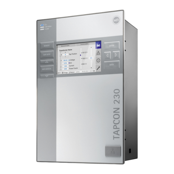
Herunterladen Inhalt Inhalt Diese Seite drucken
Vorschau ausblenden Andere Handbücher für TAPCON 230:
Inhaltsverzeichnis

Werbung

Verfügbare Sprachen
  • DE

Verfügbare Sprachen

  • DEUTSCH, seite 166
Voltage regulator • Regulador de tensión •
Spannungsregler • Régulateur de tension •
Regulador de tensão
®
TAPCON
230
Installation instructions • Instrucciones de montaje • Montageanleitung •
Instructions de montage • Instruções de montagem
7820658/02 EN-ES-DE-FR-PT

Werbung

Inhaltsverzeichnis
loading

Inhaltszusammenfassung für MR TAPCON 230

  • Seite 1 Voltage regulator • Regulador de tensión • Spannungsregler • Régulateur de tension • Regulador de tensão ® TAPCON Installation instructions • Instrucciones de montaje • Montageanleitung • Instructions de montage • Instruções de montagem 7820658/02 EN-ES-DE-FR-PT...
  • Seite 3 Table of contents Índice Inhaltsverzeichnis Sommaire Índice EN ....................5 ES ..................... 83 DE ................... 165 FR ................... 245 PT ................... 327...
  • Seite 5: Voltage Regulator

    Voltage regulator ® TAPCON Installation instructions 7820658/02...
  • Seite 6 © All rights reserved by Maschinenfabrik Reinhausen Dissemination and reproduction of this document and use and disclosure of its content are strictly prohibited unless expressly permitted. Infringements will result in liability for compensation. All rights reserved in the event of the granting of patents, utility models or designs.
  • Seite 7: Inhaltsverzeichnis

    Table of contents Table of contents Introduction........................ 10 Manufacturer.............................  10 Completeness...........................  10 Safekeeping............................ 10 Safety.......................... 11 Appropriate use .......................... 11 Inappropriate use.......................... 12 Fundamental safety instructions .......................  12 Personnel qualification........................ 14 Personal protective equipment ...................... 15 IT security..........................  16 General .............................  16 Product description......................
  • Seite 8 Table of contents Assembly variants.......................... 28 6.3.1 Flush panel mounting............................ 28 6.3.2 Wall mounting with housing (optional) ........................ 30 Connecting device .......................... 32 6.4.1 Cable recommendation ............................ 32 6.4.2 Electromagnetic compatibility.......................... 33 6.4.3 Connecting cables to the system periphery ...................... 36 6.4.4 Connecting the CAN bus............................. 36 6.4.5 Connecting SCADA............................. 39 6.4.6...
  • Seite 9 Table of contents 10.11 Tap position capture / resistor contact series ...................  66 10.12 Ambient conditions ...........................  66 10.13 Standards and directives ........................ 67 10.14 Connection diagrams........................ 68 TAPCON® 230 Basic............................ 69 TAPCON® 230 Pro ............................. 71 TAPCON® 230 Expert ............................ 74 TAPCON® 230 AVT............................ 77 List of key words ......................
  • Seite 10: Introduction

    Keep this technical document and all supporting documents ready at hand and accessible for future use at all times. Download the operating instruc- tions from the device. The operating instructions are also available on the Maschinenfabrik Reinhausen GmbH website and in the MR Customer Portal. ® TAPCON...
  • Seite 11: Safety

    2 Safety 2 Safety ▪ Read this technical file through to familiarize yourself with the product. ▪ This technical file is a part of the product. ▪ Print the downloaded document or store it on a data carrier, which is al- ways ready at hand and accessible for future at all times.
  • Seite 12: Inappropriate Use

    2 Safety 2.2 Inappropriate use Use is considered to be inappropriate if the product is used other than as de- scribed in the Intended use section. In addition, observe the following: ▪ The product is not a protective device. Do not use it to handle safety-re- lated functions.
  • Seite 13 2 Safety Invisible laser radiation Looking directly into the beam or the reflected beam can cause eye damage. The beam is emitted at the optical connections or at the end of the fiber-optic cables connected to them on the assemblies. Read the chapter "Technical Data"...
  • Seite 14: Personnel Qualification

    2 Safety Ambient conditions To ensure reliable and safe operation, the product must only be operated under the ambient conditions specified in the technical data. ▪ Observe the specified operating conditions and requirements for the in- stallation location. Modifications and conversions Unauthorized or inappropriate changes to the product may lead to personal injury, material damage and operational faults.
  • Seite 15: Personal Protective Equipment

    2 Safety Operator The operator uses and operates the product in line with this technical file. The operating company provides the operator with instruction and training on the specific tasks and the associated potential dangers arising from im- proper handling. Technical Service We strongly recommend having maintenance, repairs and retrofitting carried out by our Technical Service department.
  • Seite 16: It Security

    3 IT security 3 IT security Observe the following recommendations to operate the product safely. 3.1 General ▪ Ensure that only authorized personnel have access to the device. ▪ Only use the device within an ESP (electronic security perimeter). Do not connect the device to the Internet in an unprotected state.
  • Seite 17: Product Description

    4 Product description 4 Product description 4.1 Function description of the voltage regulation The device keeps the output voltage of a transformer with an on-load tap- changer constant. The device compares the transformer's measured voltage (U ) with a de- actual fined reference voltage (U ).
  • Seite 18: Scope Of Delivery

    4 Product description 4.2 Scope of delivery Check the shipment for completeness based on the shipping documents. ▪ Voltage regulator ▪ RJ45 patch cables ▪ Shield clamps ▪ Plug connectors ▪ Tension clamps ▪ Technical documents ▪ Additional nameplate ▪ Terminating resistor for CAN bus ▪...
  • Seite 19: Leds

    4 Product description 6 Display 7 Front interface RJ45 Ethernet interface 8 ENTER key Confirm selection/save modified parame- ters 9 LEFT cursor Navigate to the left in the menu 10 RIGHT cursor Navigate to the right in the menu 11 BACK key Exit the current menu.
  • Seite 20: Connections And Fuses

    4 Product description 4.3.3 Connections and fuses The connections are located on the rear of the device. You will find more in- formation on the connections in the Technical data [►Section 10, Page 55] section. Figure 4: Rear 1 F2 Internal fuse for the 2 X9 Power supply power supply...
  • Seite 21 4 Product description Connections and terminals Figure 5: Connections/terminals 1 COM-X6 CAN bus /SCADA 2 COM-X5 Interface for patch cable for interface RS485 SCADA via fiber-optic cable resistor contact se- ries 3 COM-X4 Fiber-optic cable 4 COM-X3 SCADA interface RS232 (SFP cage for the SFP module) 5 COM-X2 Interface for visual- 6 COM-X1...
  • Seite 22: Nameplate

    4 Product description 4.3.4 Nameplate Figure 6: Nameplate on the rear of the device 4.3.5 Safety markings Warning of a danger point. Read the information given in the product oper- ating instructions. 4.3.6 Connection diagram and grounding screw Figure 7: Connection diagram/grounding screw 1 Grounding screw 2 Connection diagram ®...
  • Seite 23: Visualization

    4 Product description 4.3.7 Visualization 4.3.7.1 Main screen Home Measured values Communication Transformer name Home 101.5 V Position Events 20 s 100.4 V Voltage 100.0 V 0.3% Information Current 40 mA 98.5 V Power factor Change Reboot admin 2020-04-15 10:08 Settings Figure 8: Home 1 Secondary navigation or naviga- 2 Primary navigation tion path 3 Status bar...
  • Seite 24 4 Product description Measured values/display Transformer name Position Measured values Communication Voltage 100.4 V Transformer name Home 101.5 V Position 0.3% Events Current 40 mA 20 s 100.4 V Voltage 100.0 V 0.3% Power factor Information Current 40 mA 98.5 V Power factor Change Reboot admin 2020-04-15 10:08 Settings Figure 9: Measured values 1 Transformer name (can be edited)
  • Seite 25: Packaging, Transport And Storage

    5 Packaging, transport and storage 5 Packaging, transport and storage 5.1 Suitability, structure and production The goods are packaged in a sturdy cardboard box. This ensures that the shipment is secure when in the intended transportation position and that none of its parts touch the loading surface of the means of transport or touch the ground after unloading.
  • Seite 26: Storage Of Shipments

    5 Packaging, transport and storage Visible damage If external transport damage is detected on receipt of the shipment, proceed as follows: ▪ Immediately record the transport damage found in the shipping docu- ments and have this countersigned by the carrier. ▪...
  • Seite 27: Mounting

    6 Mounting 6 Mounting DANGER Electric shock! Risk of fatal injury due to electrical voltage. Always observe the following safety regulations when working in or on electrical equipment. ► Disconnect the equipment. ► Lock the equipment to prevent an unintentional restart. ►...
  • Seite 28: Minimum Distances

    6 Mounting 6.2 Minimum distances NOTICE Damage to the device! Insufficient circulation of ambient air can result in damage to the device due to overheating. ► Keep the ventilation slots clear. ► Ensure sufficient distance to neighboring components. ► Only mount device in horizontal position (ventilation slots are at the top and bottom).
  • Seite 29 6 Mounting Dimensions for the control panel cutout B: 202 mm (7.95 in) Figure 12: Dimensions for the cutout 1. Cut out the section for the control panel. Figure 13: Cutting out the section for the control panel 2. Slide the device into the cutout from the front and insert tension clamps. Figure 14: Inserting the device into the cutout ®...
  • Seite 30: Wall Mounting With Housing (Optional)

    6 Mounting 3. Secure the device using the tension clamps. Figure 15: Securing device ð The device is mounted and can be wired up. 6.3.2 Wall mounting with housing (optional) For wall mounting, the device is fixed to the wall in a housing. The housing is an optional accessory.
  • Seite 31 6 Mounting ► Fix the device on the wall from behind using 4 screws (M5) Figure 17: Wall mounting ð The device is mounted and can be wired up Proceed with wiring as shown in the connection diagram and as described in the Connecting device section.
  • Seite 32: Connecting Device

    6 Mounting 6.4 Connecting device WARNING Electric shock! Connection errors can lead to death, injury or property damage. ► Ground the device with a protective conductor using the grounding screw on the housing. ► Note the phase difference of the secondary terminals for the current transformer and voltage transformer.
  • Seite 33: Electromagnetic Compatibility

    6 Mounting Excessive line capacitance can prevent the relay contacts from interrupting the contact current. In control circuits operated with alternating current, take into account the effect of the line capacitance of long control cables on the function of the relay contacts. If you want to route Ethernet connections from a control cabinet or building, we recommend using fiber-optic cables (in accordance with the IEC 61850-90-4 recommendation).
  • Seite 34 6 Mounting ▪ Separate system parts must be joined by a potential equalization. ▪ The device and its wiring must be at least 10 m away from circuit-break- ers, load disconnectors and busbars. 6.4.2.2 Wiring requirement of operating site Note the following when wiring the operating site: ▪...
  • Seite 35: Wiring Requirement In Control Cabinet

    6 Mounting Figure 19: Recommended connection of the shielding 1 Connection of the shielding via a 2 Full-surface connection of the single conductor shielding 6.4.2.3 Wiring requirement in control cabinet Note the following when wiring in the control cabinet: ▪ The control cabinet where the device will be installed must be prepared in accordance with EMC requirements: –...
  • Seite 36: Connecting Cables To The System Periphery

    6 Mounting Figure 20: Ground strap connection 6.4.3 Connecting cables to the system periphery To obtain a better overview when connecting cables, only use as many leads as necessary. To connect cables to the system periphery, proceed as follows: ü Use only the specified cables for wiring. Note the cable recommendation. ►...
  • Seite 37 6 Mounting Variant 1: The connected devices share the same potential 1. Connect all devices to a potential equalization rail to equalize the poten- tial. 2. Connect the CAN bus cable shielding to all connected devices. Variant 2: The connected devices have different potential levels Note that the shielding is less effective with this variant.
  • Seite 38 6 Mounting ► Position the cable shielding, screw into place using the shield clamp pro- vided and provide strain relief (using a cable tie). Figure 22: Shield clamp and strain relief 6.4.4.2 Mounting terminating resistor of CAN bus If you want to operate the device in parallel operation, you need to mount a 120 Ω...
  • Seite 39: Connecting Scada

    6 Mounting 6.4.5 Connecting SCADA Only available for the TAPCON® 230 Expert and AVT variants. Damage to the device! NOTICE Using the wrong data cable may damage the device. ► Only use data cables which comply with the description below. Depending on the control system used, you have to connect the device with one of the following versions.
  • Seite 40 6 Mounting 2. Position the cable shielding, screw it into the shield clamp provided, and provide strain relief (using a cable tie). Figure 25: Shield clamp and strain relief 3. Connect the COM-X1 RJ45 interface and the CPU-X4 interface together using the patch cable. 6.4.5.2 Serial RS232 (D-SUB 9-pole) interface Data cable To connect the device via the RS232 interface, use a data cable with the fol-...
  • Seite 41 6 Mounting D-SUB 9-pole plug connection Only use 9-pole D-SUB plugs with the following characteristics: ▪ Plug housing is metallic or metal-plated ▪ Cable shielding is connected with the plug using one of the following two variants: – Shielding is screwed down with traction relief. –...
  • Seite 42 6 Mounting Fiber-optic cable, 1,310 nm Multimode 1. Slide the SFP module into the COM-X4 interface and fold down the clasp Figure 28: Engaging the SFP module 2. Remove the SFP module dust plug. Figure 29: Remove the dust protection 3. Insert the fiber-optic cable with LC duplex into the SFP module COM-X4 interface.
  • Seite 43: Ethernet Interface

    6 Mounting 4. Connect the COM-X5 to the CPU-X2 using the supplied patch cable. Figure 30: Connecting CPU-X5 and COM-X2 Serial fiber-optic cable You will need the CM-0847 FO converter if you want to connect your control system via the serial fiber-optic cable. ►...
  • Seite 44 6 Mounting Miniature circuit breaker Safety fuse Characteristics B, C, K or Z Fast-acting, medium-act- ing or delayed-acting Rated switching capacity 50 kA For installation in accordance with IEC 61010-2-30 CAT II: 10 kA Table 5: Permissible fuse types 1. Voltage measurement: Feed the wires into the terminals UI:X7-4 (N con- ductor) and UI:X7-3 (L conductor) and fasten them using a screwdriver.
  • Seite 45: Wiring Analog Inputs Ai

    6 Mounting 6.4.7 Wiring analog inputs AI NOTICE Damage to the device and sensors! Incorrectly connected and configured analog inputs/outputs may result in damage to the device and sensor. ► Follow information about connecting analog sensors. ► Configure analog inputs and outputs according to the connected sensors. You can connect the following types of analog sensors: ▪...
  • Seite 46: Wiring Digital Outputs Do

    6 Mounting Auxiliary power supply for digital inputs 1. Feed the wires into the terminals X8:2 and X8:1 of the X8 plug in accor- dance with the connection diagram [►Section 10.14, Page 68] and fas- ten them using a screwdriver. 2.
  • Seite 47 6 Mounting Miniature circuit breaker You must fuse the power supply circuit with a miniature circuit breaker. The miniature circuit breaker must have the following properties: ▪ Rated current: 6...10 A ▪ Triggering characteristic: C, K or Z Conductor cross-section For the power supply circuit, use a conductor cross-section suitable for the miniature circuit breaker that you have selected, but at least 1.5 mm (AWG 15).
  • Seite 48: Performing Tests

    ► Prior to commissioning, check the supply voltage and the measured volt- age. ► Connecting the device to mains. ð The display shows the MR logo and then the operating screen. ð The voltage display LED on the top left of the device's front panel lights ®...
  • Seite 49: Initial Steps

    7 Initial steps 7 Initial steps NOTICE Damage to device and system periphery An incorrectly connected device can cause damage to the device and sys- tem periphery. ► Check the entire configuration before commissioning. As soon as the device has powered up and the start screen is displayed, you will be asked to make the following settings: 7.1 Establishing connection to visualization A connection to the visualization can be established using two interfaces:...
  • Seite 50 7 Initial steps 3. Connect the PC and the device via the front interface using an Ethernet cable (RJ45 plug). Figure 36: Establishing a connection via the front interface 4. Enter the visualization's IP address http://192.168.165.1, or if SSL encryption is active, enter https://192.168.165.1 in the browser on the PC.
  • Seite 51 Download the operating instructions from the device to start device parame- terization. ► Select the MR logo in the status line. ð The operating instructions will be downloaded. The document is also available for download in the MR Customer Portal and on our website www.reinhausen.com. ® Maschinenfabrik Reinhausen GmbH 2021...
  • Seite 52: Fault Elimination

    8 Fault elimination 8 Fault elimination This chapter describes how to rectify simple operating faults. 8.1 General faults Characteristics/details Cause Remedy No function No power supply Check the power supply. ▪ Power supply LED does not Fuse tripped Contact Maschinenfabrik Reinhausen GmbH. light up No function Configuration error...
  • Seite 53: Other Faults

    8 Fault elimination 8.3 Other faults If you cannot resolve a problem, please contact Maschinenfabrik Rein- hausen. Please have the following data to hand: ▪ Serial number – Nameplate – Info screen ▪ Software version Please provide answers to the following questions: ▪...
  • Seite 54: Disposal

    9 Disposal 9 Disposal Observe the national requirements applicable in the country of use. ® TAPCON 7820658/02 EN Maschinenfabrik Reinhausen GmbH 2021...
  • Seite 55: Technical Data

    10 Technical data 10 Technical data 10.1 Display elements Display 5″ TFT colour display LEDs 3 LEDs for operation display and messages ▪ POWER, AVR STATUS, ALARM ▪ RAISE, LOWER, AUTO, MANUAL, REMOTE 10.2 Materials Front Aluminum, plastic Tray/rear Stainless steel 10.3 Dimensions W x H x D 218 mm x 324 mm x 130 mm (8.58 in x 12.76 in x...
  • Seite 56: Voltage Measurement And Current Measurement

    10 Technical data Auxiliary power supply AUX DC DI 110 V DC for digital inputs The auxiliary power supply is used exclusively for the acquisition of up to 16 floating contacts. Output voltage : 110 V DC ± 2% (short-circuit proof) Max. output power 5 W Overvoltage category OC III...
  • Seite 57: Central Processing Unit

    10 Technical data Continuous overvoltage 550 V AC Surge test voltage 5 kV, 1.2 µs / 50 µs (IEC 60255-27) Current measurement Frequency 45…65 Hz Nominal current I 1 A or 5 A (switchable) Accuracy < ±0.5% x I in the operating temperature range Load resistance < 0.1 VA Overload capability continu- 12.5 A Overload capacity short-term 500 A / 1 s Surge test voltage 5 kV, 1.2 µs / 50 µs (IEC 60255-27)
  • Seite 58 10 Technical data ON: Relay is energized OFF: Relay is de-energized Interfaces Interface Description ER_NO ER_NC ER_COM WD_NO WD_NC WD_COM Table 14: Plug terminal CPU:X1 Interface X2, X3 Description RXD- RXD+ TXD- TXD+ Table 15: Ethernet interface CPU:X2/X3 Interface X4 Description TXD+/RXD+ TXD-/RXD- Table 16: Serial interface RS485 CPU:X4 ®...
  • Seite 59: Digital Inputs

    10 Technical data Interface X5 Description DTR (O) DCD (I) RXD (I) TXD (O) VCC/OUT 5 V/12 V RTS (O) CTS (I) Table 17: Serial interface RS232 CPU:X5 10.7 Digital inputs DI 16 Inputs (plug-based electrical 2 x 8 isolation) Nominal voltage 110 V DC Max. operating voltage 143 V DC Logical 0 ≤...
  • Seite 60: Digital Outputs

    10 Technical data Interface Description Common reference (common) Common reference (common) Input 17 Input 16 Input 15 Input 14 Input 13 Input 12 Input 11 Input 10 Table 20: Connector X2 (group 1) 10.8 Digital outputs TAPCON® 230 basic ▪ 8 relays Relay outputs DC 24 up to 220 V, AC ▪...
  • Seite 61: Electric Shock

    10 Technical data Figure 37: Contact load capacity of digital outputs with resistive load Electric shock! CAUTION The outputs of the DO assembly have plug-based electrical isolation. A mix- ture of voltage ranges (e.g. extra low voltage and low voltage) or various phases within a plug can lower the protection against electric shock.
  • Seite 62: Analog Inputs

    10 Technical data Interface Description Common reference (common) output 5 Common reference (common) output 4 Output 5 Output 4 Table 24: Connector X3 (group 2) Interface Description Common reference (common) output 7 Common reference (common) output 6 Output 7 Output 6 Table 25: Connector X4 (group 3) 10.9 Analog inputs AI 4 Inputs (electrically isolated)
  • Seite 63 10 Technical data Interface Description V0 U- voltage input V0 I- current input V0 I+ current output V0 U+ voltage output Table 27: Connector X1 (group 0) Interface Description V1 U- voltage input V1 I- current input V1 I+ current output V1 U+ voltage output Table 28: Connector X2 (group 1) Interface Description V2 U- voltage input...
  • Seite 64: Communication Interfaces

    10 Technical data 10.10 Communication interfaces Description Assembly for converting interfaces and media Interfaces 1x RS232/RS485 (RJ45): COM X1 2x Ethernet (RJ45): COM X2, COM X5 1x RS232 (D-SUB): COM X3 1x duplex LC (SFP): COM X4 1x plug terminal 10-pin: COM X6 COM X1 Internal system interface for connecting the COM X6 interface to the central processing...
  • Seite 65 10 Technical data Interface Description CTS (I) (RS232); TXD-/RXD- (RS485) RTS (O) (RS232); TXD+/RXD+ (RS485) VCC/OUT 5 V/12 V (RS232) TXD (O) (RS232) RXD (I) (RS232) DCD (I) (RS232) DTR (O) (RS232) Table 31: COM X1 (RS232/RS485) Interface Description TxD+ TxD- RxD+ RxD- Table 32: COM X2, COM X5 (RJ45) Interface Description...
  • Seite 66: Tap Position Capture / Resistor Contact Series

    10 Technical data Interface Description GND (resistor contact series) I out (resistor contact series) U+ in (resistor contact series) U- in (resistor contact series) Data- (RS485) GND (RS485) Data+ (RS485) CAN L (CAN bus) CAN GND (CAN bus) CAN H (CAN bus) Table 35: COM X6 10.11 Tap position capture / resistor contact series Electrical isolation...
  • Seite 67: Standards And Directives

    10 Technical data 10.13 Standards and directives Electromagnetic compatibility IEC 61000-6-2, IEC 61000-6-4, IEC 61000-6-5 EN 60255-26 KN 61000-6-2, KN 61000-6-4 FCC 47 CFR Part 15 B ICES-003 Electrical safety IEC 61010-1 IEC 61010-2-201 IEC 61010-2-030 EN 61010-1 UL 61010-1 CAN/CSA-C22.2 No. 61010-1 Measurement relays and protective de- IEC 60255-1:2009 Section 6.10.1, 6.10.2 vices and 6.10.4 IEC 60255-27:2013 Section 10.6.4.2,...
  • Seite 68: Connection Diagrams

    10 Technical data 10.14 Connection diagrams Also refer to 2 TAPCON® 230 Basic [► 69] 2 TAPCON® 230 Pro [► 71] 2 TAPCON® 230 Expert [► 74] 2 TAPCON® 230 AVT [► 77] ® TAPCON 7820658/02 EN Maschinenfabrik Reinhausen GmbH 2021...
  • Seite 69: Tapcon® 230 Basic

    TAPCON® 230 - BASIC CENTRAL PROCESSING UNIT POWER SUPPLY DIGITAL OUTPUTS DO 8-1 DIGITAL INPUTS DI 16-110V AC/DC N (L-) L1 (L+) 110V DC X7,X1 connection 29.09.21 LAINER LANGUAGE: PROJECT: DATE 22.01.2021 DEL BCD 16.09.21 BECK EXEC. BECK TAPCON® 230 BASIC BCD signals 28.06.21 M Kahn...
  • Seite 70 CUSTOMER VISU / SERVICE RJ45 RJ45 RJ45 RJ45 X7,X1 connection 29.09.21 LAINER LANGUAGE: PROJECT: DATE 22.01.2021 DEL BCD 16.09.21 BECK EXEC. BECK TAPCON® 230 BASIC BCD signals 28.06.21 M Kahn VERIFIED SHEET 7826272_03 MODIFICATION DATE NAME STANDARD ORIGIN. REPL. REPL.BY...
  • Seite 71: Tapcon® 230 Pro

    TAPCON® 230 - PRO CENTRAL PROCESSING UNIT POWER SUPPLY DIGITAL OUTPUTS DO 8-1 DIGITAL INPUTS DI 16-110V AC/DC N (L-) L1 (L+) 110V DC LANGUAGE: PROJECT: DATE 22.01.2021 X7,X1 connection 29.09.21 Lainer EXEC. BECK TAPCON® 230 PRO BCD signals 29.06.21 M Kahn VERIFIED SHEET...
  • Seite 72 TAPCON® 230 - PRO CENTRAL PROCESSING UNIT DIGITAL OUTPUTS DO 8-2 ANALOG INPUTS AI 4 COM - 120 Ω (II) 100% TAP POSITION POSITION TRANSMITTER MODULE, RESISTOR-TYPE (III) Ω LANGUAGE: PROJECT: DATE 22.01.2021 X7,X1 connection 29.09.21 Lainer EXEC. BECK TAPCON® 230 PRO BCD signals 29.06.21 M Kahn...
  • Seite 73 CUSTOMER VISU / SERVICE RJ45 RJ45 RJ45 RJ45 LANGUAGE: PROJECT: DATE 22.01.2021 X7,X1 connection 29.09.21 Lainer EXEC. BECK TAPCON® 230 PRO BCD signals 29.06.21 M Kahn VERIFIED SHEET 7870259_02 MODIFICATION DATE NAME STANDARD ORIGIN. REPL. REPL.BY...
  • Seite 74: Tapcon® 230 Expert

    TAPCON® 230 - EXPERT CENTRAL PROCESSING UNIT POWER SUPPLY DIGITAL OUTPUTS DO 8-1 DIGITAL INPUTS DI 16-110V AC/DC N (L-) L1 (L+) 110V DC LANGUAGE: PROJECT: DATE 22.01.2021 X7,X1,X6 connection 01.10.21 LAINER EXEC. BECK TAPCON® 230 EXPERT BCD Signal 30.06.21 KAHN VERIFIED SHEET...
  • Seite 75 TAPCON® 230 - EXPERT CENTRAL PROCESSING UNIT DIGITAL OUTPUTS DO 8-2 ANALOG INPUTS AI 4 COM - 120 Ω (II) 100% TAP POSITION POSITION TRANSMITTER MODULE, RESISTOR-TYPE (III) Ω LANGUAGE: PROJECT: DATE 22.01.2021 X7,X1,X6 connection 01.10.21 LAINER EXEC. BECK TAPCON® 230 EXPERT BCD Signal 30.06.21 KAHN...
  • Seite 76 CUSTOMER VISU / SERVICE RJ45 RJ45 RJ45 RJ45 SCADA ETHERNET LC 1310nm RJ45 RJ45 RJ45 SCADA SERIAL SIGNAL RS232 RJ45 SIGNAL Data - RS485 Data + RJ45 LANGUAGE: PROJECT: DATE 22.01.2021 X7,X1,X6 connection 01.10.21 LAINER EXEC. BECK TAPCON® 230 EXPERT BCD Signal 30.06.21 KAHN...
  • Seite 77: Tapcon® 230 Avt

    TAPCON® 230 - AVT CENTRAL PROCESSING UNIT POWER SUPPLY DIGITAL OUTPUTS DO 8-1 DIGITAL INPUTS DI 16-110V AC/DC N (L-) L1 (L+) 110V DC LANGUAGE: PROJECT: DATE 22.01.2021 X7,X1,X6 connection 01.10.21 LAINER EXEC. BECK TAPCON® 230 AVT BCD SIGNAL 30.06.21 KAHN VERIFIED SHEET...
  • Seite 78 TAPCON® 230 - AVT CENTRAL PROCESSING UNIT DIGITAL OUTPUTS DO 8-2 ANALOG INPUTS AI 4 COM - 120 Ω (II) 100% TAP POSITION POSITION TRANSMITTER MODULE, RESISTOR-TYPE (III) Ω LANGUAGE: PROJECT: DATE 22.01.2021 X7,X1,X6 connection 01.10.21 LAINER EXEC. BECK TAPCON® 230 AVT BCD SIGNAL 30.06.21 KAHN...
  • Seite 79 CUSTOMER VISU / SERVICE RJ45 RJ45 RJ45 RJ45 SCADA ETHERNET LC 1310nm RJ45 RJ45 RJ45 SCADA SERIAL SIGNAL RS232 RJ45 SIGNAL Data - RS485 Data + RJ45 LANGUAGE: PROJECT: DATE 22.01.2021 X7,X1,X6 connection 01.10.21 LAINER EXEC. BECK TAPCON® 230 AVT BCD SIGNAL 30.06.21 KAHN...
  • Seite 80: List Of Key Words

    List of key words List of key words Cable recommendation  32 Operating instructions Visualization Control system  39 Download  51 Connection  49 Electromagnetic compatibility  33 Rectifying faults  52 Wall mounting  30 Housing  30 SCADA Connection  39 ® TAPCON 7820658/02 EN Maschinenfabrik Reinhausen GmbH 2021...
  • Seite 82 Maschinenfabrik Reinhausen GmbH Falkensteinstrasse 8 93059 Regensburg +49 (0)941 4090-0 sales@reinhausen.com www.reinhausen.com ® 7820658/02 - TAPCON 230 - - 10/21 - Maschinenfabrik Reinhausen GmbH 2021 THE POWER BEHIND POWER.
  • Seite 83 Regulador de tensión ® TAPCON Instrucciones de montaje 7820658/02...
  • Seite 84 © Todos los derechos reservados por Maschinenfabrik Reinhausen Queda prohibida cualquier reproducción o copia de este documento, así como la utilización y divulgación de su contenido, a no ser que se autorice expresamente. Las infracciones conllevan una indemnización por daños. Reservados todos los derechos para casos de registro de patente, modelo de utilidad y diseño industrial.
  • Seite 85 Índice Índice Introducción........................ 88 Fabricante............................ 88 Integridad............................ 88 Lugar de almacenamiento ........................  88 Seguridad ..........................  89 Uso adecuado...........................  89 Uso inadecuado.......................... 90 Instrucciones de seguridad básicas.................... 90 Cualificación del personal.........................  92 Equipo de protección personal ...................... 93 Seguridad TI........................ 95 Generalidades ..........................
  • Seite 86 Índice Variantes de montaje........................ 108 6.3.1 Montaje en tablero ............................ 108 6.3.2 Montaje mural con carcasa (opcional) ...................... 110 Conexión del aparato........................ 112 6.4.1 Recomendación de cables.......................... 112 6.4.2 Compatibilidad electromagnética ........................ 113 6.4.3 Conexión de líneas en la periferia de la instalación.................. 116 6.4.4 Conexión de bus CAN............................ 116 6.4.5 Conexión de SCADA............................ 119...
  • Seite 87 Índice 10.11 Registro de la posición de toma/corona potenciométrica ...............  146 10.12 Condiciones ambientales........................  147 10.13 Normas y directivas ........................ 147 10.14 Esquemas de conexiones.......................  149 TAPCON® 230 Basic............................ 150 TAPCON® 230 Pro ............................ 152 TAPCON® 230 Expert ............................ 155 TAPCON® 230 AVT............................ 158 Índice de palabras clave ....................
  • Seite 88: Introducción

    ▪ instrucciones de servicio – Disponible como descarga en el aparato – Disponible como descarga en www.reinhausen.com – Disponible como descarga en el portal de clientes MR 1.3 Lugar de almacenamiento Guarde esta documentación técnica así como todos los documentos aplica- bles al alcance de la mano y accesibles en todo momento para su posterior uso.
  • Seite 89: Seguridad

    2 Seguridad 2 Seguridad ▪ Lea la documentación técnica para familiarizarse con el producto. ▪ Esta documentación técnica forma parte del producto. ▪ Imprima el documento descargado o guárdelo en un soporte de datos, que siempre esté a mano y sea accesible en todo momento. ▪...
  • Seite 90: Uso Inadecuado

    2 Seguridad 2.2 Uso inadecuado Por uso inadecuado se entiende un uso del producto distinto al descrito en el apartado Uso adecuado. Tenga en cuenta además lo siguiente: ▪ El producto no es un equipo de protección. No lo utilice para representar funciones relevantes para la seguridad.
  • Seite 91 2 Seguridad Radiación láser invisible Si mira directamente el rayo o el rayo que se refleja puede sufrir lesiones oculares. El rayo sale de las conexiones ópticas o del extremo de los cables de fibra óptica conectados a las mismas en los módulos. Lea también al res- pecto el capítulo "Datos técnicos"...
  • Seite 92: Cualificación Del Personal

    2 Seguridad Condición medioambiental Con el fin de garantizar un funcionamiento fiable y seguro, el producto úni- camente debe accionarse bajo las condiciones ambientales indicadas en los datos técnicos. ▪ Tenga en cuenta las condiciones de servicio indicadas y los requisitos del lugar de instalación.
  • Seite 93: Equipo De Protección Personal

    2 Seguridad Personas con formación en electrotecnia Una persona con formación en electrotecnia recibe instrucciones y forma- ción por parte de un técnico electricista sobre las tareas que se le han enco- mendado y los posibles peligros en caso de comportamiento indebido así como sobre los dispositivos de protección y las medidas de protección.
  • Seite 94 2 Seguridad Visor Para proteger el rostro de piezas que puedan salir dis- paradas o de salpicaduras de líquido, así como de otras sustancias peligrosas. Casco de protección Para proteger de piezas o materiales que puedan caer o salir disparados. Protección auditiva Para proteger de posibles daños en los oídos.
  • Seite 95: Seguridad Ti

    3 Seguridad TI 3 Seguridad TI Tenga en cuenta las siguientes recomendaciones para un funcionamiento seguro del producto. 3.1 Generalidades ▪ Asegúrese de que solo personas autorizadas tengan acceso al aparato. ▪ Utilice el aparato únicamente dentro de una zona de seguridad electróni- ca (ESP –...
  • Seite 96: Descripción Del Producto

    4 Descripción del producto 4 Descripción del producto 4.1 Descripción de la función de la regulación de tensión El aparato sirve para mantener constante la tensión de salida de un transfor- mador con cambiador de tomas bajo carga. El aparato compara la tensión de medición del transformador U con una Real tensión de consigna definida U...
  • Seite 97: Volumen De Entrega

    4 Descripción del producto 4.2 Volumen de entrega Compruebe la integridad de la remesa basándose en los documentos de ex- pedición. ▪ Regulador de tensión ▪ Cable patch RJ45 ▪ Abrazaderas para blindajes ▪ Conectores de enchufe ▪ Abrazaderas de sujeción ▪...
  • Seite 98: Led

    4 Descripción del producto 5 Tecla BAJAR Enviar una orden de mando al acciona- miento a motor para disminuir la ten- sión. 6 Display 7 Interfaz frontal Interfaz Ethernet RJ45 8 Tecla INTRO Confirmar la selección/guardar paráme- tros modificados 9 CURSOR hacia la izquierda Navegación por el menú...
  • Seite 99: Conexiones Y Fusibles

    4 Descripción del producto 3 LED ALARMA Rojo Se enciende en cuanto se produce un evento rojo. Amarillo Se enciende en cuanto se produce un evento amarillo. Azul Se enciende si no hay ningún evento pendiente o si se produce un evento gris.
  • Seite 100 4 Descripción del producto Conexiones y bornes Figura 5: Conexiones/bornes 1 COM-X6 Interfaz de bus 2 COM-X5 Interfaz para cable patch para /SCADA SCADA mediante cable de fi- RS485 /corona po- bra óptica tenciométrica 3 COM-X4 Cable de fibra ópti- 4 COM-X3 Interfaz SCADA RS232 (SFP Cage pa- ra el módulo SFP)
  • Seite 101: Placa De Características

    4 Descripción del producto 4.3.4 Placa de características Figura 6: Placa de características en la parte posterior del aparato 4.3.5 Identificaciones de seguridad Advertencia sobre un punto de peligro. Lea las indicaciones de las instruc- ciones de servicio del producto. 4.3.6 Esquema de conexiones y tornillo de puesta a tierra Figura 7: Esquema de conexiones/tornillo de puesta a tierra 1 Tornillo de puesta a tierra 2 Esquema de conexiones...
  • Seite 102: Visualización

    4 Descripción del producto 4.3.7 Visualización 4.3.7.1 Pantalla principal Inicio Valores de medición Comunicación Nombre del transformador Inicio 101,5 V Toma Eventos 20 s 100,4 V Tensión 100,0 V 0,3 % Información Corriente 40 mA 98,5 V Factor de potencia Change Reboot admin 15/04/2020 10:08 Ajustes Figura 8: Inicio 1 navegación secundaria o ruta de 2 navegación primaria navegación...
  • Seite 103 4 Descripción del producto Valores de medición/visualización Nombre del transformador Toma Valores de medición Comunicación Tensión 100,4 V Nombre del transformador Inicio 101,5 V Toma 0,3 % Eventos Corriente 40 mA 20 s 100,4 V Tensión 100,0 V 0,3 % Factor de potencia Información Corriente 40 mA 98,5 V Factor de potencia Change...
  • Seite 104: Embalaje, Transporte Y Almacenamiento

    5 Embalaje, transporte y almacenamiento 5 Embalaje, transporte y almacenamiento 5.1 Adecuación, diseño y fabricación Este producto está embalado en una caja de cartón resistente. Esta garanti- za que el envío se realice en la posición de transporte prevista y que ningu- no de sus componentes entre en contacto con la superficie de carga del me- dio de transporte o con el suelo.
  • Seite 105: Almacenaje De Envíos

    5 Embalaje, transporte y almacenamiento Daños visibles Si al recibir el envío se detecta algún daño de transporte externo visible, proceda como se indica a continuación: ▪ anote en los documentos de transporte los daños de transporte detecta- dos y solicite al transportista que los firme ▪...
  • Seite 106 5 Embalaje, transporte y almacenamiento ▪ Procure que los caminos de acceso estén libres. ▪ Controle periódicamente el producto almacenado, y, adicionalmente, des- pués de vendavales, fuertes lluvias, abundante nieve, etc., y tome las me- didas adecuadas. ® TAPCON 7820658/02 EN Maschinenfabrik Reinhausen GmbH 2021...
  • Seite 107: Montaje

    6 Montaje 6 Montaje PELIGRO ¡Choque eléctrico! Peligro de muerte a causa de tensión eléctrica. Al trabajar dentro y en insta- laciones eléctricas cumpla siempre las siguientes normas de seguridad. ► Desconecte la instalación. ► Proteja la instalación contra reconexión. ►...
  • Seite 108: Distancias Mínimas

    6 Montaje 6.2 Distancias mínimas AVISO ¡Daños en el aparato! Una circulación insuficiente del aire ambiente puede provocar daños en el aparato a causa de sobrecalentamiento. ► Mantenga libres las rejillas de ventilación. ► Prevea una distancia suficiente a los componentes adyacentes. ►...
  • Seite 109 6 Montaje Dimensiones para el hueco del tablero An: 202 mm (7,95 pulg.) Figura 12: Dimensiones para el hueco 1. Realice un corte en el tablero de control. Figura 13: Realización de un corte en el tablero de control 2. Inserte el aparato desde la parte delantera en el hueco e introduzca las abrazaderas de sujeción.
  • Seite 110: Montaje Mural Con Carcasa (Opcional)

    6 Montaje 3. Fije el aparato mediante las abrazaderas de sujeción. Figura 15: Fijación del aparato ð El aparato está montado y puede realizarse su cableado. 6.3.2 Montaje mural con carcasa (opcional) En el montaje mural, el aparato se fija en una carcasa en la pared. La carca- sa es un accesorio opcional.
  • Seite 111 6 Montaje ► Fije el aparato a la pared por la parte posterior con 4 tornillos M5 Figura 17: Montaje mural ð El aparato está montado y puede realizarse su cableado Para el cableado proceda según el esquema de conexiones y según se des- cribe en el apartado Conexión del aparato.
  • Seite 112: Conexión Del Aparato

    6 Montaje 6.4 Conexión del aparato ADVERTENCIA ¡Choque eléctrico! Los fallos de conexión pueden provocar la muerte, lesiones y daños mate- riales. ► Ponga el aparato a tierra con un conductor de tierra mediante el tornillo de puesta a tierra que se encuentra en la carcasa. ►...
  • Seite 113: Compatibilidad Electromagnética

    6 Montaje Las capacidades de línea demasiado elevadas pueden impedir que los con- tactos de relé interrumpan la corriente de contacto. En circuitos de control accionados por corriente alterna, tenga en cuenta la influencia de la capaci- dad de la línea en líneas de control largas sobre el funcionamiento de los contactos de relé.
  • Seite 114 6 Montaje ▪ Las partes de la instalación separadas deben estar conectadas con una conexión equipotencial. ▪ El aparato y su cableado deben mantener una distancia mínima de 10 m con los interruptores de potencia, seccionadores de potencia y carriles conductores.
  • Seite 115 6 Montaje Figura 19: Conexión recomendada del blindaje 1 conexión del blindaje mediante un 2 conexión del blindaje en toda la conductor individual superficie 6.4.2.3 Requisito sobre el cableado en el armario de conexiones Al cablear en el armario de conexiones tenga en cuenta las siguientes indi- caciones: ▪...
  • Seite 116: Conexión De Líneas En La Periferia De La Instalación

    6 Montaje Figura 20: Conexión de la cinta de masa 6.4.3 Conexión de líneas en la periferia de la instalación Al realizar la conexión, para tener una visión general más clara, cablee solo tantas líneas como sean necesarias. Para conectar las líneas en la periferia de la instalación, proceda según se indica a continuación: ü...
  • Seite 117 6 Montaje AVISO ¡Daños en el aparato! Si conecta el cable de bus CAN a aparatos que se hallan en un potencial distinto, es posible que se produzca una corriente a través del blindaje. Es- ta corriente puede provocar daños en el aparato. ►...
  • Seite 118 6 Montaje ► Aplique el blindaje del cable, atorníllelo con el borne de apantallado sumi- nistrado y fíjelo con una descarga de tracción (brida de cables). Figura 22: Borne de apantallado y descarga de tracción 6.4.4.2 Montaje de la carga óhmica del bus CAN Si desea accionar el aparato en el servicio en paralelo, debe montar una carga de 120 Ω...
  • Seite 119: Conexión De Scada

    6 Montaje 6.4.5 Conexión de SCADA Solo disponible en las variantes TAPCON® 230 Expert y AVT. ¡Daños en el aparato! AVISO El uso de cables de datos incorrectos puede provocar daños en el aparato. ► Utilice únicamente cables de datos según la siguiente descripción. En función del sistema de control utilizado, debe conectar el aparato con una de las siguientes variantes.
  • Seite 120 6 Montaje 2. Aplique el blindaje del cable, atorníllelo en el borne de apantallado sumi- nistrado y fíjelo con una descarga de tracción (brida de cables). Figura 25: Borne de apantallado y descarga de tracción 3. Conecte entre sí la interfaz RJ45 COM-X1 y la interfaz CPU-X4 mediante el cable patch.
  • Seite 121 6 Montaje Conexión de conector D-SUB de 9 polos Utilice únicamente conectores D-SUB de 9 polos con las siguientes propie- dades: ▪ La carcasa de conector es metálica o metalizada ▪ El blindaje del cable está conectado al conector según una de las dos va- riantes siguientes: –...
  • Seite 122 6 Montaje Cable de fibra óptica 1310 nm multimodo 1. Inserte el módulo SFP en la interfaz COM-X4 y pliegue el estribo Figura 28: Enclavamiento del módulo SFP 2. Retire el conector de polvo del módulo SFP. Figura 29: Desmontaje de la protección contra el polvo 3.
  • Seite 123: Cableado De La Medición De Tensión/Medición De Corriente Ui

    6 Montaje 4. Conecte entre sí las interfaces COM-X5 y CPU-X2 con el cable patch su- ministrado. Figura 30: Conexión de CPU-X5 y COM-X2 Cable de fibra óptica serial Si desea conectar su sistema de control mediante un cable de fibra óptica serial, necesitará...
  • Seite 124 6 Montaje Interruptores automáti- Fusible Característica B, C, K o Z rápido, semirretardado o lento Capacidad de ruptura asig- 50 kA nada En caso de instalación según IEC 61010-2-30 CAT II: 10 kA Tabla 5: Tipos de fusible admisibles 1. Medición de tensión: guíe los conductores en los bornes UI:X7-4 (conduc- tor N) y UI:X7-3 (conductor L) y fíjelos con un destornillador.
  • Seite 125: Cableado De Entradas Analógicas Ai

    6 Montaje 6.4.7 Cableado de entradas analógicas AI AVISO ¡Daños en el aparato y en sensores! Las entradas/salidas analógicas mal conectadas y configuradas pueden provocar daños en el aparato y el sensor. ► Siga las indicaciones para la conexión de sensores analógicos. ►...
  • Seite 126: Cableado De Entradas Digitales Di

    6 Montaje 6.4.8 Cableado de entradas digitales DI Si utiliza las entradas digitales, estas deben alimentarse con una tensión au- xiliar de 110 V CC. 1. Introduzca los conductores según el esquema de conexiones [►Apartado 10.14, Página 149] en el borne del conector DI 16-110 V y fíjelos con ayu- da de un destornillador.
  • Seite 127 6 Montaje Los medios adecuados pueden ser dispositivos seccionadores según IEC 60947-1 e IEC 60947-3 (p. ej. interruptores de potencia). Al seleccionar el tipo de seccionador tenga en cuenta las propiedades de los correspon- dientes circuitos de corriente (tensión, corrientes máximas). Tenga en cuen- ta además lo siguiente: ▪...
  • Seite 128: Ejecución De Comprobaciones

    ► Conecte el aparato a la red eléctrica. ð El display muestra el logotipo de MR y, a continuación, la pantalla de servicio. ð El LED Indicación de tensión situado arriba a la izquierda en la placa frontal del aparato está...
  • Seite 129: Primeros Pasos

    7 Primeros pasos 7 Primeros pasos AVISO Daños en el aparato y en la periferia de la instalación Un aparato conectado de forma incorrecta puede provocar daños en el apa- rato y en la periferia de la instalación. ► Antes de la puesta en servicio, compruebe todo el circuito. En cuanto el aparato haya arrancado y muestre la pantalla de inicio, se le solicitará...
  • Seite 130 7 Primeros pasos 3. Conecte el PC y el aparato mediante el cable Ethernet (conector RJ45) a través de la interfaz frontal. Figura 36: Establecimiento de la conexión mediante interfaz frontal 4. Entre la dirección IP de la visualización http://192.168.165.1, o con codificación SSL activada https://192.168.165.1, en el PC en el na- vegador.
  • Seite 131 Descárguese las instrucciones de servicio del aparato para empezar la pa- rametrización del aparato. ► En la barra de estado seleccione el logotipo de MR. ð Se descargan las instrucciones de servicio. Alternativamente, puede descargarse el documento desde el portal de clien- tes MR o nuestra página web www.reinhausen.com.
  • Seite 132: Solución De Averías

    8 Solución de averías 8 Solución de averías Este capítulo describe la solución de averías de funcionamiento sencillas. 8.1 Averías generales Expresión/Detalle Causa Solución Ninguna función No hay alimentación de corriente Compruebe la alimentación de corriente. ▪ El LED Alimentación de co- Fusible disparado Póngase en contacto con Maschinenfabrik rriente no se enciende...
  • Seite 133: Otras Averías

    8 Solución de averías 8.3 Otras averías En caso de que no se halle ninguna solución para una avería, le rogamos se ponga en contacto con Maschinenfabrik Reinhausen. Le rogamos tenga a mano los siguientes datos: ▪ Número de serie –...
  • Seite 134: Eliminación

    9 Eliminación 9 Eliminación Tenga en cuenta las disposiciones de eliminación nacionales en el país de uso correspondiente. ® TAPCON 7820658/02 EN Maschinenfabrik Reinhausen GmbH 2021...
  • Seite 135: Datos Técnicos

    10 Datos técnicos 10 Datos técnicos 10.1 Elementos de indicación Display Display de color TFT de 5" 3 LED para indicación de servicio y señalizaciones ▪ POWER, ESTADO AVR, ALARMA ▪ SUBIR, BAJAR, AUTO, MANUAL, REMOTE 10.2 Materiales Frontal Aluminio, plástico Cuba/parte trasera Acero inoxidable 10.3 Dimensiones...
  • Seite 136: Medición De Tensión Y Medición De Corriente

    10 Datos técnicos Alimentación de corriente auxiliar AUX DC DI de 110 V CC para entradas digitales La alimentación de corriente auxiliar sirve únicamente para registrar hasta 16 contactos libres de potencial. Tensión de salida : 110 V CC ± 2 % (resistente a corto- circuitos) Potencia de salida máx.
  • Seite 137: Unidad De Cálculo Central

    10 Datos técnicos Medición de tensión TAPCON® 230 AVT Rango de medición (conmu- 132...280 V CA 228…510 V CA table) Tensión consigna U 230 V CA 400 V CA Precisión < ± 0,3 % x U en el rango de temperatura de servi- Categoría de medición (IEC CAT III con una posición de altura de 2.000 m 61010-2-30) CAT II con una posición de altura de 3.000 m Sobretensión permanente...
  • Seite 138 10 Datos técnicos Potencia de conmutación 30 W máx. Tensión transitoria asignada 2,0 kV Comportamiento de respuesta del Watchdog/Error Relais: Error Relais Watchdog Relais Power Off Arranque Ready (ningún error pen- diente) Ready (error pendiente) ON: el relé está excitado OFF: el relé ha fallado Interfaces Interfaz Descripción...
  • Seite 139: Entradas Digitales

    10 Datos técnicos Interfaz X4 Descripción TXD+/RXD+ TXD-/RXD- Tabla 16: Interfaz serial RS485 CPU:X4 Interfaz X5 Descripción DTR (O) DCD (I) RXD (I) TXD (O) VCC/OUT 5 V/12 V RTS (O) CTS (I) Tabla 17: Interfaz serial RS232 CPU:X5 10.7 Entradas digitales DI 16 Entradas (separadas galvá- 2 x 8 nicamente enchufe por en-...
  • Seite 140 10 Datos técnicos Interfaz Descripción Referencia común (Common) Referencia común (Common) Entrada 7 Entrada 6 Entrada 5 Entrada 4 Entrada 3 Entrada 2 Entrada 1 Entrada 0 Tabla 19: Conector X1 (grupo 0) Interfaz Descripción Referencia común (Common) Referencia común (Common) Entrada 17 Entrada 16 Entrada 15...
  • Seite 141: Salidas Digitales

    10 Datos técnicos 10.8 Salidas digitales TAPCON® 230 basic ▪ 8 relés Salidas de relé CC 24 hasta 220 V, CA ▪ 4 grupos por cada módulo, separados 230 V galvánicamente TAPCON® 230 pro/expert/AVT ▪ 16 relés ▪ 4 grupos por cada módulo, separados galvánicamente Tensión de conmutación 24 V CC/48 V CC/60 V CC/110 V...
  • Seite 142 10 Datos técnicos Interfaz Descripción Referencia común (Common) salida 1 Referencia común (Common) salida 0 Salida 1 Salida 0 Tabla 22: Conector X1 (grupo 0) Interfaz Descripción Referencia común (Common) salida 3 Referencia común (Common) salida 2 Salida 3 Salida 2 Tabla 23: Conector X2 (grupo 1) Interfaz Descripción...
  • Seite 143: Entradas Analógicas

    10 Datos técnicos 10.9 Entradas analógicas AI 4 Entradas (separadas galvánica- 4 x 1 mente) Rango de medición -20…+20 mA, sobrecorriente aprox. 20 % -10…+10 V, sobretensión aprox. 30 % Precisión 0,15 % a 25 °C Corriente 0,2 % a 0…50 °C 0,3 % a -20…70 °C 0,4 % a -40…70 °C tensión...
  • Seite 144: Interfaces De Comunicación

    10 Datos técnicos Interfaz Descripción V2 U- entrada de tensión V2 I- entrada de corriente V2 I+ salida de corriente V2 U+ salida de tensión Tabla 29: Conector X3 (grupo 2) Interfaz Descripción V3 U- entrada de tensión V3 I- entrada de corriente V3 I+ salida de corriente V3 U+ salida de tensión Tabla 30: Conector X4 (grupo 3)
  • Seite 145 10 Datos técnicos COM-X4 Módulo SFP para convertir Ethernet (RJ45) a cable de fibra óptica para SCADA Solo disponible en las variantes TAPCON® 230 Expert y AVT. ▪ Máx. 2000 m ▪ 100 MBit/s ▪ Diodo emisor de luz: clase 1 ▪ Longitud de onda: 1310 nm ▪...
  • Seite 146: Registro De La Posición De Toma/Corona Potenciométrica

    10 Datos técnicos Interfaz Descripción Tabla 33: COM-X3 (RS232) Interfaz Descripción Fibra de vidrio 50/125 y 62,5/125 multimodo Tabla 34: COM-X4 (Duplex-LC SFP) Interfaz Descripción GND (corona potenciométrica) I out (corona potenciométrica) U+ in (corona potenciométrica) U- in (corona potenciométrica) Data - (RS485) GND (RS485) Data + (RS485) CAN-L (bus CAN)
  • Seite 147: Condiciones Ambientales

    10 Datos técnicos 10.12 Condiciones ambientales Temperatura de servicio -25...+70 °C Temperatura de almace- -30...+85 °C (con batería) namiento Humedad relativa 5...95 % sin condensación Grado de contaminación Clase de protección Grado de protección En la parte frontal: IP54 Lado trasero: IP20 Con armario de conexiones opcional: IP66 Altura de uso máxima 3000 m sobre el nivel del mar Distancia mínima a otros...
  • Seite 148 10 Datos técnicos Pruebas de resistencia medio ambiente IEC 60255-21-1 oscilaciones clase 1 (3 ciclos, 0,5 g aceleración 1 octava/min o 60 ciclos, 1,0 g aceleración, 1 octava/ min) IEC 60255-21-2 choques clase 1 (dura- ción 11 ms, 5 g o 15 g aceleración, n.º ejes 3) IEC 60255-21-3 terremotos clase 1 (fre- cuencia 1-35 Hz, 3,5 mm/1 g aceleración...
  • Seite 149: Esquemas De Conexiones

    10 Datos técnicos 10.14 Esquemas de conexiones Para ello vea también 2 TAPCON® 230 Basic [► 150] 2 TAPCON® 230 Pro [► 152] 2 TAPCON® 230 Expert [► 155] 2 TAPCON® 230 AVT [► 158] ® Maschinenfabrik Reinhausen GmbH 2021 7820658/02 EN TAPCON...
  • Seite 150: Tapcon® 230 Basic

    TAPCON® 230 - BASIC UNIDAD DE CÁLCULO CENTRAL ALIMENTACION SALIDAS DIGITALES DO 8-1 ENTRADAS DIGITALES DI 16-110V AC/DC N (L-) L1 (L+) 110V DC X7,X1 connection 29.09.21 LAINER LANGUAGE: PROJECT: DATE 22.01.2021 DEL BCD 16.09.21 BECK EXEC. BECK TAPCON® 230 BASIC BCD signals 28.06.21 M Kahn...
  • Seite 151 CUSTOMER VISU / SERVICE RJ45 RJ45 RJ45 RJ45 X7,X1 connection 29.09.21 LAINER LANGUAGE: PROJECT: DATE 22.01.2021 DEL BCD 16.09.21 BECK EXEC. BECK TAPCON® 230 BASIC BCD signals 28.06.21 M Kahn VERIFIED SHEET 7870247_03 MODIFICATION DATE NAME STANDARD ORIGIN. REPL. REPL.BY...
  • Seite 152: Tapcon® 230 Pro

    TAPCON® 230 - PRO UNIDAD DE CÁLCULO CENTRAL ALIMENTACION SALIDAS DIGITALES DO 8-1 ENTRADAS DIGITALES DI 16-110V AC/DC N (L-) L1 (L+) 110V DC LANGUAGE: PROJECT: DATE 22.01.21 X7,X1 connection 29.09.21 Lainer EXEC. BECK TAPCON® 230 PRO BCD signals 29.06.21 M Kahn VERIFIED SHEET...
  • Seite 153 TAPCON® 230 - PRO UNIDAD DE CÁLCULO CENTRAL SALIDAS DIGITALES DO 8-2 ENTRADAS ANALÓGICAS AI 4 COM - 120 Ω (II) 100% SEÑAL DE POSICIÓN MÓDULO INDICADOR DE POSICIÓN VERSIÓN POTENCIOMETRICA (III) Ω LANGUAGE: PROJECT: DATE 22.01.21 X7,X1 connection 29.09.21 Lainer EXEC.
  • Seite 154 CUSTOMER VISU / SERVICE RJ45 RJ45 RJ45 RJ45 LANGUAGE: PROJECT: DATE 22.01.21 X7,X1 connection 29.09.21 Lainer EXEC. BECK TAPCON® 230 PRO BCD signals 29.06.21 M Kahn VERIFIED SHEET 7870261_02 MODIFICATION DATE NAME STANDARD ORIGIN. REPL. REPL.BY...
  • Seite 155: Tapcon® 230 Expert

    TAPCON® 230 - EXPERT UNIDAD DE CÁLCULO CENTRAL ALIMENTACION SALIDAS DIGITALES DO 8-1 ENTRADAS DIGITALES DI 16-110V AC/DC N (L-) L1 (L+) 110V DC LANGUAGE: PROJECT: DATE 22.01.21 X7,X1,X6 connection 01.10.21 LAINER EXEC. BECK TAPCON® 230 EXPERT BCD Signal 30.06.21 KAHN VERIFIED SHEET...
  • Seite 156 TAPCON® 230 - EXPERT UNIDAD DE CÁLCULO CENTRAL SALIDAS DIGITALES DO 8-2 ENTRADAS ANALÓGICAS AI 4 COM - 120 Ω (II) 100% SEÑAL DE POSICIÓN MÓDULO INDICADOR DE POSICIÓN VERSIÓN POTENCIOMETRICA (III) Ω LANGUAGE: PROJECT: DATE 22.01.21 X7,X1,X6 connection 01.10.21 LAINER EXEC.
  • Seite 157 CUSTOMER VISU / SERVICE RJ45 RJ45 RJ45 RJ45 SCADA ETHERNET LC 1310nm RJ45 RJ45 RJ45 SCADA SERIAL SIGNAL RS232 RJ45 SIGNAL Data - RS485 Data + RJ45 LANGUAGE: PROJECT: DATE 22.01.21 X7,X1,X6 connection 01.10.21 LAINER EXEC. BECK TAPCON® 230 EXPERT BCD Signal 30.06.21 KAHN...
  • Seite 158: Tapcon® 230 Avt

    TAPCON® 230 - AVT UNIDAD DE CÁLCULO CENTRAL ALIMENTACION SALIDAS DIGITALES DO 8-1 ENTRADAS DIGITALES DI 16-110V AC/DC N (L-) L1 (L+) 110V DC LANGUAGE: PROJECT: DATE 22.01.2021 X7,X1,X6 connection 01.10.21 LAINER EXEC. BECK TAPCON® 230 AVT BCD SIGNAL 30.06.2021 KAHN VERIFIED SHEET...
  • Seite 159 TAPCON® 230 - AVT UNIDAD DE CÁLCULO CENTRAL SALIDAS DIGITALES DO 8-2 ENTRADAS ANALÓGICAS AI 4 COM - 120 Ω (II) 100% SEÑAL DE POSICIÓN MÓDULO INDICADOR DE POSICIÓN VERSIÓN POTENCIOMETRICA (III) Ω LANGUAGE: PROJECT: DATE 22.01.2021 X7,X1,X6 connection 01.10.21 LAINER EXEC.
  • Seite 160 CUSTOMER VISU / SERVICE RJ45 RJ45 RJ45 RJ45 SCADA ETHERNET LC 1310nm RJ45 RJ45 RJ45 SCADA SERIAL SIGNAL RS232 RJ45 SIGNAL Data - RS485 Data + RJ45 LANGUAGE: PROJECT: DATE 22.01.2021 X7,X1,X6 connection 01.10.21 LAINER EXEC. BECK TAPCON® 230 AVT BCD SIGNAL 30.06.2021 KAHN...
  • Seite 161: Índice De Palabras Clave

    Índice de palabras clave Índice de palabras clave Carcasa  110 Montaje mural  110 SCADA Compatibilidad electromagnética Conexión  119  113 Sistema de control  119 Solucionar averías  132 Recomendación de cables  112 Instrucciones de servicio Descarga  131 Visualización Descargar  131 Conexión  129 ®...
  • Seite 164 Maschinenfabrik Reinhausen GmbH Falkensteinstrasse 8 93059 Regensburg +49 (0)941 4090-0 sales@reinhausen.com www.reinhausen.com ® 7820658/02 - TAPCON 230 - - 10/21 - Maschinenfabrik Reinhausen GmbH 2021 THE POWER BEHIND POWER.
  • Seite 165 Spannungsregler ® TAPCON Montageanleitung 7820658/02...
  • Seite 166 © Alle Rechte bei Maschinenfabrik Reinhausen Weitergabe sowie Vervielfältigung dieses Dokumentes, Verwertung und Mitteilung seines Inhalts sind verboten, soweit nicht ausdrücklich gestattet. Zuwiderhandlungen verpflichten zu Schadenersatz. Alle Rechte für den Fall der Patent-, Gebrauchsmuster- und Geschmacksmustereintragung vorbehalten. Nach Redaktionsschluss der vorliegenden Dokumentation können sich am Produkt Änderungen ergeben haben. Änderungen der technischen Daten bzw.
  • Seite 167 Inhaltsverzeichnis Inhaltsverzeichnis Einleitung ........................ 170 Hersteller ............................ 170 Vollständigkeit.......................... 170 Aufbewahrungsort...........................  170 Sicherheit ........................ 171 Bestimmungsgemäße Verwendung.................... 171 Bestimmungswidrige Verwendung .................... 172 Grundlegende Sicherheitshinweise .................... 172 Qualifikation des Personals ...................... 174 Persönliche Schutzausrüstung .......................  175 IT-Sicherheit........................ 177 Allgemeines ............................  177 Produktbeschreibung ....................
  • Seite 168 Inhaltsverzeichnis Montagevarianten ...........................  189 6.3.1 Schalttafeleinbau............................... 189 6.3.2 Wandmontage mit Gehäuse (optional) ...................... 191 Gerät anschließen ..........................  193 6.4.1 Kabelempfehlung .............................. 193 6.4.2 Elektromagnetische Verträglichkeit........................ 194 6.4.3 Leitungen an die Anlagenperipherie anschließen ..................... 197 6.4.4 CAN-Bus anschließen............................ 197 6.4.5 SCADA anschließen ............................ 200 6.4.6 Spannungsmessung/Strommessung UI verdrahten .................. 204 6.4.7 Analoge Eingänge AI verdrahten ........................ 206 6.4.8...
  • Seite 169 Inhaltsverzeichnis 10.11 Stufenstellungserfassung/Widerstandskontaktreihe...............  227 10.12 Umgebungsbedingungen........................  227 10.13 Normen und Richtlinien ........................ 228 10.14 Anschlussschaltbilder ........................ 230 TAPCON® 230 Basic............................ 231 TAPCON® 230 Pro ............................ 233 TAPCON® 230 Expert ............................ 236 TAPCON® 230 AVT............................ 239 Stichwortverzeichnis......................  242 ® Maschinenfabrik Reinhausen GmbH 2021 7820658/02 EN TAPCON...
  • Seite 170: Einleitung

    ▪ Betriebsanleitung – Als Download verfügbar auf dem Gerät – Als Download verfügbar unter www.reinhausen.com – Als Download verfügbar im MR-Kundenportal 1.3 Aufbewahrungsort Bewahren Sie diese technische Unterlage sowie sämtliche mitgeltenden Do- kumente griffbereit und jederzeit zugänglich für den späteren Gebrauch auf.
  • Seite 171: Sicherheit

    2 Sicherheit 2 Sicherheit ▪ Lesen Sie diese technische Unterlage durch, um sich mit dem Produkt vertraut zu machen. ▪ Diese technische Unterlage ist Teil des Produkts. ▪ Drucken Sie das heruntergeladene Dokument aus oder speichern es auf einem Datenträger, der immer griffbereit und jederzeit zugänglich ist. ▪...
  • Seite 172: Bestimmungswidrige Verwendung

    2 Sicherheit 2.2 Bestimmungswidrige Verwendung Als bestimmungswidrige Verwendung gilt, wenn das Produkt anders verwen- det wird, als es im Abschnitt Bestimmungsgemäße Verwendung beschrie- ben ist. Beachten Sie zudem Folgendes: ▪ Das Produkt ist kein Schutzgerät. Verwenden Sie es nicht, um sicher- heitsrelevante Funktionen abzubilden.
  • Seite 173 2 Sicherheit Unsichtbare Laserstrahlung Wenn Sie direkt oder in den reflektierenden Strahl blicken, kann dies das Auge schädigen. Der Strahl tritt an den optischen Anschlüssen oder am En- de der daran angeschlossenen Lichtwellenleiter an den Baugruppen aus. Lesen Sie dazu auch das Kapitel „Technischen Daten“ [►Abschnitt 10, Seite 216].
  • Seite 174: Qualifikation Des Personals

    2 Sicherheit Umgebungsbedingung Um einen zuverlässigen und sicheren Betrieb zu gewährleisten, ist das Pro- dukt nur unter den in den technischen Daten angegebenen Umgebungsbe- dingungen zu betreiben. ▪ Angegebene Betriebsbedingungen und Anforderungen an den Aufstellort beachten. Veränderungen und Umbauten Unerlaubte oder nicht sachgerechte Veränderungen des Produkts können zu Personenschäden, Sachschäden sowie Funktionsstörungen führen.
  • Seite 175: Persönliche Schutzausrüstung

    2 Sicherheit Elektrotechnisch unterwiesene Personen Eine elektrotechnisch unterwiesene Person wird durch eine Elektrofachkraft über die ihr übertragenen Aufgaben und möglichen Gefahren bei unsachge- mäßen Verhalten sowie über Schutzeinrichtungen und Schutzmaßnahmen unterrichtet und angelernt. Die elektrotechnisch unterwiesene Person arbei- tet ausschließlich unter der Leitung und Aufsicht einer Elektrofachkraft. Bediener Der Bediener nutzt und bedient das Produkt im Rahmen dieser technischen Unterlage.
  • Seite 176 2 Sicherheit Schutzhelm Zum Schutz vor herabfallenden und umherfliegenden Teilen und Materialien. Gehörschutz Zum Schutz vor Gehörschäden. Schutzhandschuhe Zum Schutz vor mechanischen, thermischen und elektri- schen Gefährdungen. Tabelle 1: Persönliche Schutzausrüstung ® TAPCON 7820658/02 EN Maschinenfabrik Reinhausen GmbH 2021...
  • Seite 177: It-Sicherheit

    3 IT-Sicherheit 3 IT-Sicherheit Beachten Sie nachfolgende Empfehlungen für den sicheren Betrieb des Pro- dukts. 3.1 Allgemeines ▪ Stellen Sie sicher, dass nur befugte Personen Zugang zum Gerät haben. ▪ Verwenden Sie das Gerät ausschließlich innerhalb einer elektronischen Sicherheitszone (ESP – electronic security perimeter). Verbinden Sie das Gerät nicht ungeschützt mit dem Internet.
  • Seite 178: Produktbeschreibung

    4 Produktbeschreibung 4 Produktbeschreibung 4.1 Funktionsbeschreibung der Spannungsregelung Das Gerät dient dazu, die Ausgangsspannung eines Transformators mit Laststufenschalter konstant zu halten. Das Gerät vergleicht die Messspannung des Transformators U mit einer definierten Sollspannung U . Die Differenz von U zu U stellt die Regel- Soll Soll...
  • Seite 179: Lieferumfang

    4 Produktbeschreibung 4.2 Lieferumfang Prüfen Sie die Lieferung anhand der Versandpapiere auf Vollständigkeit. ▪ Spannungsregler ▪ Patchkabel RJ45 ▪ Schirmschellen ▪ Steckverbinder ▪ Spannklemmen ▪ Technische Unterlagen ▪ Zusätzliches Typenschild ▪ Abschlusswiderstand für CAN-Bus ▪ Abschlusswiderstand für RS485-Bus Optional ▪ Gehäuse für die Wandmontage ▪...
  • Seite 180: Leds

    4 Produktbeschreibung 6 Display 7 Frontschnittstelle Ethernet-Schnittstelle RJ45 8 Taste ENTER Auswahl bestätigen/veränderte Parame- ter speichern 9 CURSOR links Navigation im Menü nach links 10 CURSOR rechts Navigation im Menü nach rechts 11 Taste BACK Aktuelles Menü verlassen. In vorherige Menüebene gelangen Nur im Handbetrieb möglich.
  • Seite 181: Anschlüsse Und Sicherungen

    4 Produktbeschreibung 4.3.3 Anschlüsse und Sicherungen Auf der Rückseite des Geräts befinden sich die Anschlüsse. Weitere Infor- mationen zu den Anschlüssen finden Sie im Abschnitt Technische Daten [►Abschnitt 10, Seite 216]. Abbildung 4: Rückseite 1 F2 Interne Sicherung für die 2 X9 Spannungsversorgung Stromversorgung 3 F1...
  • Seite 182 4 Produktbeschreibung Anschlüsse und Klemmen Abbildung 5: Anschlüsse/Klemmen 1 COM-X6 CAN-Bus /SCADA- 2 COM-X5 Schnittstelle für Patchkabel für Schnittstelle SCADA über Lichtwellenleiter RS485 /Wider- standskontaktreihe 3 COM-X4 Lichtwellenleiter 4 COM-X3 SCADA-Schnittstelle RS232 (SFP-Cage für das SFP-Modul) 5 COM-X2 Schnittstelle für die 6 COM-X1 Schnittstelle für Patchkabel für Visualisierung über...
  • Seite 183: Typenschild

    4 Produktbeschreibung 4.3.4 Typenschild Abbildung 6: Typenschild auf der Rückseite des Geräts 4.3.5 Sicherheitskennzeichnungen Warnung vor einer Gefahrenstelle. Lesen Sie die Hinweise in der Betriebs- anleitung des Produkts. 4.3.6 Anschlussschaltbild und Erdungsschraube Abbildung 7: Anschlussschaltbild/Erdungsschraube 1 Erdungsschraube 2 Anschlussschaltbild ® Maschinenfabrik Reinhausen GmbH 2021 7820658/02 EN TAPCON...
  • Seite 184: Visualisierung

    4 Produktbeschreibung 4.3.7 Visualisierung 4.3.7.1 Hauptbildschirm Home Messwerte Kommunikation Transformatorname Home 101.5 V Stufe Ereignisse 100.4V Spannung 100.0 V 0.3% Information Strom 40mA 98.5 V Leistungsfaktor Change Reboot admin 15.04.2020 10:08 Einstellunge Abbildung 8: Home 1 Sekundärnavigation oder Navigati- 2 Primärnavigation onspfad 3 Statusleiste 4 Anzeigebereich...
  • Seite 185 4 Produktbeschreibung Messwerte/Anzeige Transformatorname Stufe Messwerte Kommunikation Spannung 100.4V Transformatorname Home 101.5 V Stufe 0.3% Ereignisse Strom 40mA 100.4V Spannung 100.0 V 0.3% Leistungsfaktor Information Strom 40mA 98.5 V Leistungsfaktor Change Reboot admin 15.04.2020 10:08 Einstellunge Abbildung 9: Messwerte 1 Transformatorbezeichnung (edi- 2 Stufenstellung tierbar) 3 Aktuelle Messwerte: Spannung,...
  • Seite 186: Verpackung, Transport Und Lagerung

    5 Verpackung, Transport und Lagerung 5 Verpackung, Transport und Lagerung 5.1 Eignung, Aufbau und Herstellung Die Verpackung des Packgutes erfolgt in einem stabilen Pappkarton. Dieser gewährleistet, dass die Sendung in der vorgesehenen Transportlage sicher steht und keines ihrer Teile die Ladefläche des Transportmittels oder nach dem Abladen den Boden berühren.
  • Seite 187: Sendungen Einlagern

    5 Verpackung, Transport und Lagerung Sichtbare Schäden Stellen Sie beim Empfang der Sendung äußerlich sichtbare Transportschä- den fest, verfahren Sie wie folgt: ▪ Tragen Sie den festgestellten Transportschaden sofort in die Frachtpapie- re ein und lassen Sie vom Abliefernden gegenzeichnen. ▪...
  • Seite 188: Montage

    6 Montage 6 Montage GEFAHR Elektrischer Schlag! Lebensgefahr durch elektrische Spannung. Bei Arbeiten in und an elektri- schen Anlagen stets folgende Sicherheitsregeln einhalten. ► Anlage freischalten. ► Anlage gegen Wiedereinschalten sichern. ► Spannungsfreiheit allpolig feststellen. ► Erden und kurzschließen. ► Benachbarte, unter Spannung stehende Teile abdecken oder abschran- ken.
  • Seite 189: Mindestabstände

    6 Montage 6.2 Mindestabstände ACHTUNG Schäden am Gerät! Unzureichende Zirkulation der Umgebungsluft kann zu Schäden am Gerät durch Überhitzung führen. ► Lüftungsschlitze freihalten. ► Ausreichend Abstand zu benachbarten Bauteilen vorsehen. ► Gerät nur in horizontaler Lage montieren (Lüftungsschlitze befinden sich oben und unten).
  • Seite 190 6 Montage Maße für den Schalttafelausschnitt B: 202 mm (7.95 in) Abbildung 12: Maße für den Ausschnitt 1. Ausschnitt in Schalttafel herstellen. Abbildung 13: Ausschnitt in Schalttafel herstellen 2. Gerät von vorne in den Ausschnitt einschieben und Spannklemmen ein- setzen. Abbildung 14: Gerät in den Ausschnitt einsetzen ®...
  • Seite 191: Wandmontage Mit Gehäuse (Optional)

    6 Montage 3. Gerät über die Spannklemmen befestigen. Abbildung 15: Gerät befestigen ð Das Gerät ist montiert und kann verdrahtet werden. 6.3.2 Wandmontage mit Gehäuse (optional) Bei der Wandmontage wird das Gerät in einem Gehäuse an der Wand be- festigt. Das Gehäuse ist ein optionales Zubehör. Bohren Sie gemäß...
  • Seite 192 6 Montage ► Das Gerät mit 4 Schrauben M5 von hinten an der Wand befestigen Abbildung 17: Wandmontage ð Das Gerät ist montiert und kann verdrahtet werden Gehen Sie bei der Verdrahtung gemäß Anschlussschaltbild und wie in Ab- schnitt Gerät anschließen beschrieben vor. ®...
  • Seite 193: Gerät Anschließen

    6 Montage 6.4 Gerät anschließen WARNUNG Elektrischer Schlag! Anschlussfehler können zu Tod, Verletzung und Sachschäden führen. ► Gerät über die am Gehäuse angebrachte Erdungsschraube mit einem Schutzleiter erden. ► Phasenlage der Sekundäranschlüsse vom Stromwandler und Span- nungswandler beachten. ► Ausgangsrelais an den Motorantrieb korrekt anschließen. Führen Sie Spannungen über Trenneinrichtungen zu und stellen Sie sicher, dass Strompfade kurzgeschlossen werden können.
  • Seite 194: Elektromagnetische Verträglichkeit

    6 Montage Zu hohe Leitungskapazitäten können verhindern, dass die Relaiskontakte den Kontaktstrom unterbrechen. Berücksichtigen Sie in wechselstrombetä- tigten Steuerstromkreisen den Einfluss der Leitungskapazität von langen Steuerleitungen auf die Funktion der Relaiskontakte. Wenn Sie Ethernet-Verbindungen aus einem Schaltschrank oder Gebäude herausführen wollen, empfehlen wir die Verwendung von Lichtwellenleitern (gemäß...
  • Seite 195: Anforderung An Die Verdrahtung Des Betriebsorts

    6 Montage ▪ Getrennte Anlagenteile müssen durch einen Potentialausgleich verbun- den sein. ▪ Das Gerät und seine Verdrahtung müssen einen Mindestabstand von 10 m zu Leistungsschaltern, Lasttrennern und Stromschienen einhalten. 6.4.2.2 Anforderung an die Verdrahtung des Betriebsorts Beachten Sie bei der Verdrahtung des Betriebsorts nachfolgende Hinweise: ▪...
  • Seite 196: Anforderung An Die Verdrahtung Im Schaltschrank

    6 Montage Abbildung 19: Empfohlene Anbindung der Abschirmung 1 Anbindung der Abschirmung über 2 Vollflächige Anbindung der Ab- eine Einzelader schirmung 6.4.2.3 Anforderung an die Verdrahtung im Schaltschrank Beachten Sie bei der Verdrahtung im Schaltschrank nachfolgende Hinweise: ▪ Der Schaltschrank für den Einbau des Geräts ist EMV-gerecht vorzuberei- ten: –...
  • Seite 197: Leitungen An Die Anlagenperipherie Anschließen

    6 Montage Abbildung 20: Anschluss des Massebands 6.4.3 Leitungen an die Anlagenperipherie anschließen Für eine bessere Übersicht beim Anschluss nur so viele Leitungen verdrah- ten, wie nötig. Um die Leitungen an der Anlagenperipherie anzuschließen, gehen Sie wie folgt vor: ü Verwenden Sie zum Verdrahten ausschließlich spezifizierte Kabel. Beach- ten Sie die Kabelempfehlung.
  • Seite 198 6 Montage ACHTUNG Schäden am Gerät! Wenn Sie das CAN-Bus-Kabel an Geräten anschließen, die auf unter- schiedlichem Potenzial liegen, kann es zum Stromfluss über die Abschir- mung kommen. Dieser Strom kann Schäden am Gerät hervorrufen. ► Geräte zum Potenzialausgleich an einer Potenzialausgleichsschiene an- schließen.
  • Seite 199: Abschlusswiderstand Des Can-Busses Montieren

    6 Montage ► Abschirmung des Kabels auflegen und mit der mitgelieferten Schirmklem- me verschrauben sowie mit einer Zugentlastung (Kabelbinder) befestigen. Abbildung 22: Schirmklemme und Zugentlastung 6.4.4.2 Abschlusswiderstand des CAN-Busses montieren Wenn Sie das Gerät im Parallelbetrieb betreiben möchten, müssen Sie an beiden Enden des CAN-Busses einen Abschlusswiderstand von 120 Ω...
  • Seite 200: Scada Anschließen

    6 Montage 6.4.5 SCADA anschließen Nur bei den Varianten TAPCON® 230 Expert und AVT vorhanden. Schäden am Gerät! ACHTUNG Die Verwendung falscher Datenkabel kann zu Schäden am Gerät führen. ► Ausschließlich Datenkabel gemäß der nachfolgenden Beschreibung ver- wenden. Abhängig vom verwendeten Leitsystem, müssen Sie das Gerät mit einer der folgenden Varianten anschließen.
  • Seite 201 6 Montage 2. Abschirmung des Kabels auflegen und in die mitgelieferte Schirmklemme verschrauben sowie mit einer Zugentlastung (Kabelbinder) befestigen. Abbildung 25: Schirmklemme und Zugentlastung 3. Die RJ45-Schnittstelle COM-X1 und die Schnittstelle CPU-X4 mit Hilfe des Patchkabels miteinander verbinden. 6.4.5.2 Serielle Schnittstelle RS232 (D-SUB 9-polig) Datenkabel Für den Anschluss des Geräts über die RS232-Schnittstelle ein Datenkabel gemäß...
  • Seite 202 6 Montage Steckeranschluss D-SUB 9 polig Verwenden Sie ausschließlich 9 polige D-SUB-Stecker mit folgenden Eigen- schaften: ▪ Steckergehäuse ist metallisch oder metallisiert ▪ Abschirmung des Kabels ist gemäß einer der beiden nachfolgenden Vari- anten mit dem Stecker verbunden: – Abschirmung ist mit der Zugentlastung verschraubt. –...
  • Seite 203 6 Montage Lichtwellenleiter 1310 nm Multimode 1. Das SFP-Modul in die Schnittstelle COM-X4 einschieben und die Spange umklappen. Abbildung 28: SFP-Modul einrasten 2. Staubstecker des SFP-Moduls entfernen. Abbildung 29: Staubschutz entfernen 3. Lichtwellenleiter mit LC-Duplex in das SFP-Modul COM-X4 anschließen. ® Maschinenfabrik Reinhausen GmbH 2021 7820658/02 EN TAPCON...
  • Seite 204: Ethernet-Schnittstelle

    6 Montage 4. Die Schnittstellen COM-X5 und CPU-X2 mit dem mitgelieferten Patchka- bel miteinander verbinden. Abbildung 30: CPU-X5 und COM-X2 verbinden Serieller Lichtwellenleiter Wenn Sie Ihr Leitsystem mittels seriellem Lichtwellenleiter anschließen möchten, benötigen Sie den LWL-Konverter CM-0847 ► Den seriellen Lichtwellenleiter und den Konverter an die Schnittstelle CPU-X5 anschließen.
  • Seite 205 6 Montage Leitungsschutzschalter Schmelzsicherung Charakteristik B, C, K oder Z Flink, Mittelträge oder Träge Bemessungsschaltvermö- 50 kA Bei Installation gemäß IEC 61010-2-30 CAT II: 10 kA Tabelle 5: Zulässige Sicherungstypen 1. Spannungsmessung: Adern in die Klemmen UI:X7-4 (N-Leiter) und UI:X7-3 (L-Leiter) führen und mit Hilfe eines Schraubendrehers befesti- gen.
  • Seite 206: Analoge Eingänge Ai Verdrahten

    6 Montage 6.4.7 Analoge Eingänge AI verdrahten ACHTUNG Schäden am Gerät und an Sensoren! Fehlerhaft angeschlossene und konfigurierte analoge Eingänge/Ausgänge können zur Beschädigung des Geräts und des Sensors führen. ► Hinweise zum Anschluss analoger Sensoren befolgen. ► Analoge Eingänge und Ausgänge entsprechend der angeschlossenen Sensoren konfigurieren.
  • Seite 207: Digitale Eingänge Di Verdrahten

    6 Montage 6.4.8 Digitale Eingänge DI verdrahten Wenn Sie die digitalen Eingänge verwenden, müssen diese mit einer Hilfss- pannung von 110 V DC versorgt werden. 1. Adern gemäß Anschlussschaltbild [►Abschnitt 10.14, Seite 230] in die Klemme des Steckers DI 16-110V einführen und mit Hilfe eines Schrau- bendrehers befestigen.
  • Seite 208 6 Montage Geeignete Mittel können Trennvorrichtungen nach IEC 60947-1 und IEC 60947-3 sein (z. B. Leistungsschalter). Beachten Sie bei der Auswahl des Trennschaltertyps die Eigenschaften aus den jeweiligen Stromkreisen (Spannung, maximale Ströme). Beachten Sie zudem Folgendes: ▪ Die Trennvorrichtung muss für den Benutzer leicht erreichbar sein ▪...
  • Seite 209: Prüfungen Durchführen

    ► Vor Inbetriebnahme die Gesamtschaltung prüfen. ► Vor Inbetriebnahme die Versorgungsspannung und die Messspannung prüfen. ► Gerät an das Stromnetz anschließen. ð Das Display zeigt das MR-Logo und anschließend den Betriebsbild- schirm an. ð Die LED Spannungsanzeige oben links auf der Frontplatte des Geräts leuchtet.
  • Seite 210: Erste Schritte

    7 Erste Schritte 7 Erste Schritte ACHTUNG Schäden an Gerät und Anlagenperipherie Ein unsachgemäß angeschlossenes Gerät kann zu Schäden an Gerät und Anlagenperipherie führen. ► Vor Inbetriebnahme die Gesamtschaltung prüfen. Sobald das Gerät hochgefahren ist und den Startbildschirm anzeigt, werden Sie aufgefordert folgende Einstellungen durchzuführen: 7.1 Verbindung zur Visualisierung herstellen Sie können über 2 Schnittstellen eine Verbindung zur Visualisierung herstel-...
  • Seite 211 7 Erste Schritte 3. PC und Gerät mittels Ethernetkabel (RJ45-Stecker) über die Frontschnitt- stelle verbinden. Abbildung 36: Verbindung über die Frontschnittstelle herstellen 4. Die IP-Adresse der Visualisierung http://192.168.165.1, oder bei aktiver SSL-Verschlüsselung https://192.168.165.1, auf dem PC in den Browser eingeben. ð Die Visualisierung wird aufgerufen. Verbindung über rückseitige Schnittstelle CPU-X3 herstellen 1.
  • Seite 212 Laden Sie sich die Betriebsanleitung vom Gerät herunter, um mit der Para- metrierung des Geräts zu beginnen. ► In der Statuszeile das MR-Logo auswählen. ð Die Betriebsanleitung wird heruntergeladen. Das Dokument steht Ihnen alternativ im MR-Kundenportal oder auf unserer Website www.reinhausen.com zum Download zur Verfügung. ® TAPCON...
  • Seite 213: Störungsbeseitigung

    8 Störungsbeseitigung 8 Störungsbeseitigung Dieses Kapitel beschreibt die Beseitigung von einfachen Betriebsstörungen. 8.1 Generelle Störungen Ausprägung/Detail Ursache Abhilfe Keine Funktion Keine Stromversorgung Stromversorgung prüfen. ▪ LED Stromversorgung leuch- Sicherung ausgelöst Maschinenfabrik Reinhausen GmbH kontaktie- tet nicht ren. Keine Funktion Konfigurationsfehler Maschinenfabrik Reinhausen GmbH kontaktie- ren.
  • Seite 214: Sonstige Störungen

    8 Störungsbeseitigung 8.3 Sonstige Störungen Sollte es bei einer Störung keine auffindbare Lösung geben, kontaktieren Sie bitte die Maschinenfabrik Reinhausen. Halten Sie bitte folgende Daten bereit: ▪ Seriennummer – Typenschild – Infobildschirm ▪ Softwareversion Bereiten Sie sich auf folgende Fragen vor: ▪...
  • Seite 215: Entsorgung

    9 Entsorgung 9 Entsorgung Beachten Sie die nationalen Entsorgungsvorschriften im jeweiligen Verwen- derland. ® Maschinenfabrik Reinhausen GmbH 2021 7820658/02 EN TAPCON...
  • Seite 216: Technische Daten

    10 Technische Daten 10 Technische Daten 10.1 Anzeigeelemente Display 5" TFT-Farbdisplay LEDs 3 LEDs für Betriebsanzeige und Meldungen ▪ POWER, AVR STATUS, ALARM ▪ HÖHER, TIEFER, AUTO, MANUAL, REMOTE 10.2 Materialien Front Aluminium, Kunststoff Wanne/Rückseite Edelstahl 10.3 Abmessungen B x H x T 218 mm x 324 mm x 130 mm (8,58 in x 12,76 in x 5,12 in) (ohne Gegenstecker) Gegenstecker 20 mm (0,79 in)
  • Seite 217: Spannungsmessung Und Strommessung

    10 Technische Daten Hilfsstromversorgung AUX DC DI 110V DC für digitale Eingänge Die Hilfsstromversorgung dient ausschließlich für die Erfassung von bis zu 16 potenzialfreien Kontakten. Ausgangsspannung : 110V DC ± 2% (Kurzschlussfest) Max. Ausgangsleistung 5 W Überspannungskategorie OC III Stoßprüfspannung 5 kV, 1,2µs/50µs (IEC 60255-27) Sicherung 250 VAC, 0,08 A, 5 x 20 mm, Charakte- ristik TT (superträge), Ausschaltvermö-...
  • Seite 218: Zentrale Recheneinheit

    10 Technische Daten Dauerhafte Überspannung 550 VAC Stoßprüfspannung 5 kV, 1,2 µs / 50 µs (IEC 60255-27) Strommessung Frequenz 45…65 Hz Nennstrom I 1 A oder 5 A (umschaltbar) Genauigkeit < ± 0,5 % x I im Betriebstemperaturbereich Bürde < 0,1 VA Überlastbarkeit dauerhaft 12,5 A Überlastbarkeit kurzzeitig 500 A / 1 s Stoßprüfspannung 5 kV, 1,2 µs / 50 µs (IEC 60255-27) Schnittstelle Beschreibung VT (U : 100/230/400 V AC)
  • Seite 219 10 Technische Daten Ansprechverhalten des Watchdogs/Error Relais: Error Relais Watchdog Relais Power Off Hochlauf Ready (kein anstehender Fehler) Ready (anstehender Feh- ler) ON: Relais ist angezogen OFF: Relais ist abgefallen Schnittstellen Schnittstelle Beschreibung ER_NO ER_NC ER_COM WD_NO WD_NC WD_COM Tabelle 14: Steckklemme CPU:X1 Schnittstelle X2, X3 Beschreibung RXD-...
  • Seite 220: Digitale Eingänge

    10 Technische Daten Schnittstelle X4 Beschreibung TXD+/RXD+ TXD-/RXD- Tabelle 16: Serielle Schnittstelle RS485 CPU:X4 Schnittstelle X5 Beschreibung DTR (O) DCD (I) RXD (I) TXD (O) VCC/OUT 5V/12V RTS (O) CTS (I) Tabelle 17: Serielle Schnittstelle RS232 CPU:X5 10.7 Digitale Eingänge DI 16 Eingänge (steckerweise gal- 2 x 8 vanisch getrennt)
  • Seite 221 10 Technische Daten Schnittstelle Beschreibung Gemeinsamer Bezug (Common) Gemeinsamer Bezug (Common) Eingang 7 Eingang 6 Eingang 5 Eingang 4 Eingang 3 Eingang 2 Eingang 1 Eingang 0 Tabelle 19: Stecker X1 (Gruppe 0) Schnittstelle Beschreibung Gemeinsamer Bezug (Common) Gemeinsamer Bezug (Common) Eingang 17 Eingang 16 Eingang 15...
  • Seite 222: Digitale Ausgänge

    10 Technische Daten 10.8 Digitale Ausgänge TAPCON® 230 basic ▪ 8 Relais Relaisausgänge DC 24 bis 220 V, AC ▪ 4 Gruppen je Modul, galvanisch ge- 230 V trennt TAPCON® 230 pro/expert/AVT ▪ 16 Relais ▪ 4 Gruppen je Modul, galvanisch ge- trennt Schaltspannung 24VDC/48VDC/60VDC/110VDC/220VD...
  • Seite 223 10 Technische Daten Schnittstelle Beschreibung Gemeinsamer Bezug (Common) Ausgang 1 Gemeinsamer Bezug (Common) Ausgang 0 Ausgang 1 Ausgang 0 Tabelle 22: Stecker X1 (Gruppe 0) Schnittstelle Beschreibung Gemeinsamer Bezug (Common) Ausgang 3 Gemeinsamer Bezug (Common) Ausgang 2 Ausgang 3 Ausgang 2 Tabelle 23: Stecker X2 (Gruppe 1) Schnittstelle Beschreibung...
  • Seite 224: Analoge Eingänge

    10 Technische Daten 10.9 Analoge Eingänge AI 4 Eingänge (galvanisch getrennt) 4 x 1 Messbereich -20…+20 mA, Überstrom ca. 20% -10…+10 V, Überspannung ca. 30% Genauigkeit 0,15% bei 25°C Strom 0,2% bei 0…50°C 0,3% bei -20…70°C 0,4% bei -40…70°C Spannung 0,4% bei 0…50°C 0,5% bei -20…70°C 0,6% bei -40…70°C Eingangsimpedanz...
  • Seite 225: Kommunikationsschnittstellen

    10 Technische Daten Schnittstelle Beschreibung V2 U- Spannungseingang V2 I- Stromeingang V2 I+ Stromausgang V2 U+ Spannungsausgang Tabelle 29: Stecker X3 (Gruppe 2) Schnittstelle Beschreibung V3 U- Spannungseingang V3 I- Stromeingang V3 I+ Stromausgang V3 U+ Spannungsausgang Tabelle 30: Stecker X4 (Gruppe 3) 10.10 Kommunikationsschnittstellen Beschreibung Baugruppe zur Konvertierung der Schnittstel-...
  • Seite 226 10 Technische Daten COM-X4 SFP-Modul zur Konvertierung von Ethernet (RJ45) auf Lichtwellenleiter für SCADA Nur bei den Varianten TAPCON® 230 Expert und AVT ▪ Max. 2000 m vorhanden. ▪ 100 MBit/s ▪ Licht emittierende Diode: Klasse 1 ▪ Wellenlänge: 1310 nm ▪ Max. optische Ausgangsleistung: <1 mW (gemäß...
  • Seite 227: Stufenstellungserfassung/Widerstandskontaktreihe

    10 Technische Daten Schnittstelle Beschreibung Tabelle 33: COM-X3 (RS232) Schnittstelle Beschreibung Glasfaser 50/125 und 62,5/125 multimode Tabelle 34: COM-X4 (Duplex-LC SFP) Schnittstelle Beschreibung GND (Widerstandskontaktreihe) I out (Widerstandskontaktreihe) U+ in (Widerstandskontaktreihe) U- in (Widerstandskontaktreihe) Data - (RS485) GND (RS485) Data + (RS485) CAN-L (CAN-Bus) CAN-GND (CAN-Bus) CAN-H (CAN-Bus)
  • Seite 228: Normen Und Richtlinien

    10 Technische Daten Verschmutzungsgrad Schutzklasse Schutzart Frontseitig: IP54 Rückseitig: IP20 Mit optionalem Schaltschrank: IP66 Maximale Einsatzhöhe 3000 m über NN Mindestabstand zu ande- Oben/unten: 88,9 mm (3,5 in; entspricht 2 HE), hinten ren Geräten/Schalt- 30 mm (1,2 in) schrank Tabelle 36: Zulässige Umgebungsbedingungen 10.13 Normen und Richtlinien Elektromagnetische Verträglichkeit IEC 61000-6-2, IEC 61000-6-4, IEC...
  • Seite 229 10 Technische Daten Beständigkeitsprüfungen Umwelt IEC 60255-21-1 Schwingungen Class 1 (3 Zyklen, 0,5g Beschleunigung 1 Okta- ve/min oder 60 Zyklen, 1,0g Beschleuni- gung, 1 Oktave/min) IEC 60255-21-2 Schocken Class 1 (Dau- er 11ms, 5g bzw. 15g Beschleunigung, Anz. Achsen 3) IEC 60255-21-3 Erdbeben Class 1 (Fre- quenz 1-35Hz, 3.5mm/1g Beschleuni- gung horiz., 1.5mm/0.5g Beschleunigung...
  • Seite 230: Anschlussschaltbilder

    10 Technische Daten 10.14 Anschlussschaltbilder Sehen Sie dazu auch 2 TAPCON® 230 Basic [► 231] 2 TAPCON® 230 Pro [► 233] 2 TAPCON® 230 Expert [► 236] 2 TAPCON® 230 AVT [► 239] ® TAPCON 7820658/02 EN Maschinenfabrik Reinhausen GmbH 2021...
  • Seite 231: Tapcon® 230 Basic

    TAPCON® 230 - BASIC ZENTRALE RECHENEINHEIT SPANNUNGSVERSORGUNG DIGITALE AUSGÄNGE DO 8-1 DIGITALE EINGÄNGE DI 16-110V AC/DC N (L-) L1 (L+) 110V DC X7,X1 connection 29.09.21 LAINER LANGUAGE: PROJECT: DATE 22.01.2021 DEL BCD 16.09.21 BECK EXEC. BECK TAPCON® 230 BASIC BCD signals 28.06.21 M Kahn VERIFIED...
  • Seite 232 CUSTOMER VISU / SERVICE RJ45 RJ45 RJ45 RJ45 X7,X1 connection 29.09.21 LAINER LANGUAGE: PROJECT: DATE 22.01.2021 DEL BCD 16.09.21 BECK EXEC. BECK TAPCON® 230 BASIC BCD signals 28.06.21 M Kahn VERIFIED SHEET 7868400_03 MODIFICATION DATE NAME STANDARD ORIGIN. REPL. REPL.BY...
  • Seite 233: Tapcon® 230 Pro

    TAPCON® 230 - PRO ZENTRALE RECHENEINHEIT SPANNUNGSVERSORGUNG DIGITALE AUSGÄNGE DO 8-1 DIGITALE EINGÄNGE DI 16-110V AC/DC N (L-) L1 (L+) 110V DC LANGUAGE: PROJECT: DATE 22.01.2021 X7,X1 connection 29.09.21 Lainer EXEC. BECK TAPCON® 230 PRO BCD signals 29.06.21 M Kahn VERIFIED SHEET 7870260_02...
  • Seite 234 TAPCON® 230 - PRO ZENTRALE RECHENEINHEIT DIGITALE AUSGÄNGE DO 8-2 ANALOGE EINGÄNGE AI 4 COM - 120 Ω (II) 100% STUFENSTELLUNG STELLUNGSMELDEMODUL IN WIDERSTANDSAUSFUEHRUNG (III) Ω LANGUAGE: PROJECT: DATE 22.01.2021 X7,X1 connection 29.09.21 Lainer EXEC. BECK TAPCON® 230 PRO BCD signals 29.06.21 M Kahn VERIFIED...
  • Seite 235 CUSTOMER VISU / SERVICE RJ45 RJ45 RJ45 RJ45 LANGUAGE: PROJECT: DATE 22.01.2021 X7,X1 connection 29.09.21 Lainer EXEC. BECK TAPCON® 230 PRO BCD signals 29.06.21 M Kahn VERIFIED SHEET 7870260_02 MODIFICATION DATE NAME STANDARD ORIGIN. REPL. REPL.BY...
  • Seite 236: Tapcon® 230 Expert

    TAPCON® 230 - EXPERT ZENTRALE RECHENEINHEIT SPANNUNGSVERSORGUNG DIGITALE AUSGÄNGE DO 8-1 DIGITALE EINGÄNGE DI 16-110V AC/DC N (L-) L1 (L+) 110V DC LANGUAGE: PROJECT: DATE 22.01.2021 X7,X1,X6 connection 01.10.21 Lainer EXEC. BECK TAPCON® 230 EXPERT BCD Signal 30.06.21 KAHN VERIFIED SHEET 7870270_02 MODIFICATION...
  • Seite 237 TAPCON® 230 - EXPERT ZENTRALE RECHENEINHEIT DIGITALE AUSGÄNGE DO 8-2 ANALOGE EINGÄNGE AI 4 COM - 120 Ω (II) 100% STUFENSTELLUNG STELLUNGSMELDEMODUL IN WIDERSTANDSAUSFUEHRUNG (III) Ω LANGUAGE: PROJECT: DATE 22.01.2021 X7,X1,X6 connection 01.10.21 Lainer EXEC. BECK TAPCON® 230 EXPERT BCD Signal 30.06.21 KAHN VERIFIED...
  • Seite 238 CUSTOMER VISU / SERVICE RJ45 RJ45 RJ45 RJ45 SCADA ETHERNET LC 1310nm RJ45 RJ45 RJ45 SCADA SERIAL SIGNAL RS232 RJ45 SIGNAL Data - RS485 Data + RJ45 LANGUAGE: PROJECT: DATE 22.01.2021 X7,X1,X6 connection 01.10.21 Lainer EXEC. BECK TAPCON® 230 EXPERT BCD Signal 30.06.21 KAHN...
  • Seite 239: Tapcon® 230 Avt

    TAPCON® 230 - AVT ZENTRALE RECHENEINHEIT SPANNUNGSVERSORGUNG DIGITALE AUSGÄNGE DO 8-1 DIGITALE EINGÄNGE DI 16-110V AC/DC N (L-) L1 (L+) 110V DC LANGUAGE: PROJECT: DATE 22.01.2021 X7,X1,X6 connection 01.10.21 LAINER EXEC. BECK TAPCON® 230 AVT BCD SIGNAL 30.06.2021 KAHN VERIFIED SHEET 7870285_02 MODIFICATION...
  • Seite 240 TAPCON® 230 - AVT ZENTRALE RECHENEINHEIT DIGITALE AUSGÄNGE DO 8-2 ANALOGE EINGÄNGE AI 4 COM - 120 Ω (II) 100% STUFENSTELLUNG STELLUNGSMELDEMODUL IN WIDERSTANDSAUSFUEHRUNG (III) Ω LANGUAGE: PROJECT: DATE 22.01.2021 X7,X1,X6 connection 01.10.21 LAINER EXEC. BECK TAPCON® 230 AVT BCD SIGNAL 30.06.2021 KAHN VERIFIED...
  • Seite 241 CUSTOMER VISU / SERVICE RJ45 RJ45 RJ45 RJ45 SCADA ETHERNET LC 1310nm RJ45 RJ45 RJ45 SCADA SERIAL SIGNAL RS232 RJ45 SIGNAL Data - RS485 Data + RJ45 LANGUAGE: PROJECT: DATE 22.01.2021 X7,X1,X6 connection 01.10.21 LAINER EXEC. BECK TAPCON® 230 AVT BCD SIGNAL 30.06.2021 KAHN...
  • Seite 242: Stichwortverzeichnis

    Stichwortverzeichnis Stichwortverzeichnis Betriebsanleitung Kabelempfehlung  193 Visualisierung Download  212 Verbindung  210 herunterladen  212 Leitsystem  200 Wandmontage  191 Elektromagnetische Verträglichkeit  194 SCADA Anschluss  200 Störungen beseitigen  213 Gehäuse  191 ® TAPCON 7820658/02 EN Maschinenfabrik Reinhausen GmbH 2021...
  • Seite 244 Maschinenfabrik Reinhausen GmbH Falkensteinstrasse 8 93059 Regensburg +49 (0)941 4090-0 sales@reinhausen.com www.reinhausen.com ® 7820658/02 - TAPCON 230 - - 10/21 - Maschinenfabrik Reinhausen GmbH 2021 THE POWER BEHIND POWER.
  • Seite 245 Régulateur de tension ® TAPCON Instructions de montage 7820658/02...
  • Seite 246 © Tous droits réservés à la société Maschinenfabrik Reinhausen La transmission et la reproduction du présent document, l'exploitation et la communication de son contenu sont interdites sauf autorisation expresse. Tout manquement expose son auteur au versement de dommages et intérêts. Tous droits réservés pour le cas de la délivrance d'un brevet, d'un modèle d'utilité...
  • Seite 247 Sommaire Sommaire Introduction........................ 250 Fabricant............................ 250 Intégralité ............................ 250 Lieu de stockage.......................... 250 Sécurité ...........................  251 Utilisation conforme à l'emploi prévu .................... 251 Utilisation non conforme à l'emploi prévu .................. 252 Consignes de sécurité fondamentales....................  252 Qualification du personnel ...................... 254 Équipement de protection individuelle ....................
  • Seite 248 Sommaire Variantes de montage........................ 270 6.3.1 Montage encastré ............................. 270 6.3.2 Montage mural avec boîtier (en option) ...................... 272 Raccordement de l'appareil ...................... 274 6.4.1 Câbles recommandés ............................ 274 6.4.2 Compatibilité électromagnétique........................ 275 6.4.3 Raccorder les câbles aux périphériques ...................... 278 6.4.4 Raccordement du bus CAN .......................... 278 6.4.5 Raccordement SCADA ............................. 281 6.4.6...
  • Seite 249 Sommaire 10.11 Saisie de la position de prise/Rangée de contacts potentiométrique .......... 308 10.12 Conditions ambiantes ........................ 309 10.13 Normes et directives ........................ 309 10.14 Schémas de raccordement...................... 311 TAPCON® 230 Basic............................ 312 TAPCON® 230 Pro ............................ 314 TAPCON® 230 Expert ............................ 317 TAPCON®...
  • Seite 250: Introduction

    à portée de main et accessibles à tout moment pour une utilisation ultérieure. Téléchargez les instructions de service depuis l'appa- reil. Les instructions de service sont également disponibles sur le site web de la Maschinenfabrik Reinhausen GmbH ou dans le portail client MR. ® TAPCON...
  • Seite 251: Sécurité

    2 Sécurité 2 Sécurité ▪ Lisez cette documentation technique dans son intégralité pour vous fami- liariser avec le produit. ▪ La présente documentation technique fait partie du produit. ▪ Imprimez le document téléchargé, ou enregistrez-le sur un support de données toujours à portée de main et accessible à tout moment. ▪...
  • Seite 252: Utilisation Non Conforme À L'emploi Prévu

    2 Sécurité ▪ Le produit est prévu pour être monté. Assurez-vous que toutes les me- sures de prévention d'incendies et de protection contre une décharge électrique sont prises. ▪ Veillez à ce que la résistance aux contraintes mécaniques soit donnée. 2.2 Utilisation non conforme à...
  • Seite 253 2 Sécurité Travaux lors de l'exploitation N'utilisez le produit que si celui-ci est en parfait état de fonctionnement. Dans le cas contraire, il y a danger pour l'intégrité corporelle et la vie de l'uti- lisateur. ▪ Contrôlez régulièrement le bon fonctionnement des dispositifs de sécurité. ▪...
  • Seite 254: Qualification Du Personnel

    2 Sécurité Indications de sécurité Les panneaux d'avertissement et de sécurité sont apposés sur le produit comme indications de sécurité. Ils constituent un élément important du concept de sécurité. ▪ Observez toutes les indications de sécurité apposées sur le produit. ▪...
  • Seite 255 2 Sécurité Électricien L'électricien a suivi une formation spécialisée qui lui confère les connais- sances et les expériences requises, ainsi que la connaissance des normes et dispositions en vigueur. Qui plus est, il dispose des aptitudes suivantes : ▪ L'électricien identifie par lui-même les risques potentiels et est en mesure de les éviter.
  • Seite 256: Équipement De Protection Individuelle

    2 Sécurité 2.5 Équipement de protection individuelle Le port d'équipements de protection individuelle pendant le travail est indis- pensable dans le but de minimiser les risques pour la santé. ▪ Portez toujours les équipements de protection requis pour chaque cas pendant le travail.
  • Seite 257: Sécurité It

    3 Sécurité IT 3 Sécurité IT Veuillez observer les recommandations ci-après afin de garantir un fonction- nement en toute sécurité du produit. 3.1 Généralités ▪ Assurez-vous que seules les personnes autorisées ont accès à l'appareil. ▪ Utilisez l'appareil uniquement dans un périmètre de sécurité électronique (ESP –...
  • Seite 258: Description Du Produit

    4 Description du produit 4 Description du produit 4.1 Description fonctionnelle de la régulation de la tension L'appareil sert à maintenir constante la tension de sortie d'un transformateur avec changeur de prises en charge. L'appareil compare la tension de mesure du transformateur U à...
  • Seite 259: Contenu De La Livraison

    4 Description du produit 4.2 Contenu de la livraison Vérifiez l'intégralité de la livraison en vous basant sur les documents d'expé- dition. ▪ Régulateur de tension ▪ Câble patch RJ45 ▪ Colliers de blindage ▪ Connecteur enfichable ▪ Clips ▪ Documentation technique ▪...
  • Seite 260: Del

    4 Description du produit 4 Touche MANUAL Activer le mode de fonctionnement MA- NUAL 5 Touche DIMINUER Envoyer une instruction de contrôle au mécanisme d'entraînement pour dimi- nuer la tension. 6 Affichage 7 Interface frontale Interface Ethernet RJ45 8 Touche ENTER Confirmer la sélection/Enregistrer les pa- ramètres modifiés 9 CURSEUR à...
  • Seite 261: Raccordements Et Fusibles

    4 Description du produit 3 DEL ALARME Rouge Est allumée dès qu'un événement Rouge est présent. Jaune Est allumée dès qu'un événement Jaune est présent. Bleu Est allumée lorsqu'aucun événement n'est présent ou lorsqu'un événement Gris est présent. 4 DEL X8 sortie 110V CC Bleu Est allumée lorsque les entrées nu- mériques sont alimentées en électrici-...
  • Seite 262 4 Description du produit Raccordements et bornes Figure 5: Raccordements/Bornes 1 COM-X6 Bus CAN /interface 2 COM-X5 Interface pour câble patch SCADA RS485 pour SCADA via fibre optique rangée de contacts potentiométrique 3 COM-X4 Fibre optique (boî- 4 COM-X3 Interface SCADA RS232 tier SFP pour le mo- dule SFP) 5 COM-X2 Interface de visuali-...
  • Seite 263: Plaque Signalétique

    4 Description du produit 4.3.4 Plaque signalétique Figure 6: Plaque signalétique au dos de l'appareil 4.3.5 Indications de sécurité Mise en garde contre un danger. Veuillez lire les indications fournies dans les instructions de service du produit. 4.3.6 Schéma de raccordement et vis de mise à la terre Figure 7: Schéma de raccordement/Vis de mise à...
  • Seite 264: Visualisation

    4 Description du produit 4.3.7 Visualisation 4.3.7.1 Écran d'accueil Accueil Valeurs mesurées Communication Nom du transformateur Accueil 101,5 V Prise Événements 100,4V Tension 100,0 V 0,3% Information Courant 40mA 98,5 V Facteur de puiss. Change Reboot admin 15/04/2020 10h08 Réglages Figure 8: Accueil 1 Navigation secondaire ou chemin 2 Navigation primaire de navigation 3 Barre d'état...
  • Seite 265 4 Description du produit Valeurs mesurées/Affichage Nom du transformateur Prise Valeurs mesurées Communication Tension 100,4V Nom du transformateur Accueil 101,5 V Prise 0,3% Événements Courant 40mA 100,4V Tension 100,0 V 0,3% Facteur de puiss. Information Courant 40mA 98,5 V Facteur de puiss. Change Reboot admin 15/04/2020 10h08...
  • Seite 266 4 Description du produit Temporisation T2 uniquement pour les variantes Basic, Pro et Expert. ® TAPCON 7820658/02 EN Maschinenfabrik Reinhausen GmbH 2021...
  • Seite 267: Emballage, Transport Et Stockage

    5 Emballage, transport et stockage 5 Emballage, transport et stockage 5.1 Aptitude, structure et fabrication Le produit est emballé dans un carton solide. Celui-ci garantit la bonne te- nue du produit pendant le transport et prévient tout contact d'une des pièces avec la surface de chargement du moyen de transport ou avec le sol après le déchargement.
  • Seite 268: Stockage Des Marchandises

    5 Emballage, transport et stockage Dommages visibles Procédez comme suit si vous constatez des dommages apparents occasion- nés pendant le transport : ▪ Mentionnez immédiatement le dommage de transport constaté sur les do- cuments de transport et faites-les contresigner par la personne ayant as- suré...
  • Seite 269: Montage

    6 Montage 6 Montage DANGER Choc électrique ! Danger de mort dû à la tension électrique. Observez toujours les règles de sécurité suivantes lors de travaux dans et sur les installations électriques. ► Mettez l'installation hors tension. ► Protégez l'installation contre une remise en marche. ►...
  • Seite 270: Distances Minimales

    6 Montage 6.2 Distances minimales AVIS Endommagement de l'appareil ! La circulation insuffisante de l'air ambiant peut endommager l'appareil en raison d'une surchauffe. ► Libérer les fentes d'aération. ► Prévoir une distance suffisante par rapport aux composants avoisinants. ► Montez l'appareil uniquement en position horizontale (les fentes d'aéra- tion sont situées en haut et en bas).
  • Seite 271 6 Montage Dimensions de la découpe du tableau de commande B : 202 mm (7,95 in) Figure 12: Dimensions de découpe 1. Réalisez une découpe dans le tableau de commande. Figure 13: Réaliser une découpe dans le tableau de commande 2. Insérez l'appareil par l'avant dans la découpe et introduisez les clips. Figure 14: Insérer l'appareil dans la découpe ®...
  • Seite 272: Montage Mural Avec Boîtier (En Option)

    6 Montage 3. Fixez l'appareil avec les clips. Figure 15: Fixer l'appareil ð L'appareil est maintenant monté et peut être câblé. 6.3.2 Montage mural avec boîtier (en option) Pour le montage mural, l'appareil est fixé au mur dans un boîtier. Le boîtier est un accessoire optionnel.
  • Seite 273 6 Montage ► Fixez l'appareil au mur par l'arrière avec quatre vis M5 Figure 17: Montage mural ð L'appareil est maintenant monté et peut être câblé Procédez au câblage conformément au schéma de raccordement et comme décrit dans la section Raccorder l'appareil. ®...
  • Seite 274: Raccordement De L'appareil

    6 Montage 6.4 Raccordement de l'appareil AVERTISSEMENT Choc électrique ! Les erreurs de raccordement peuvent entraîner la mort, des blessures et des dégâts matériels. ► Avec un conducteur de protection, mettez l'appareil à la terre à l'aide de la vis de mise à la terre située sur le boîtier. ►...
  • Seite 275: Compatibilité Électromagnétique

    6 Montage Des capacités de ligne trop élevées peuvent empêcher la coupure du cou- rant de contact par les contacts de relais. Tenez compte, dans les circuits de contrôle actionnés par le courant alternatif, de l'influence de la capacité des lignes de commande longues sur le fonctionnement des contacts de re- lais.
  • Seite 276 6 Montage ▪ Les pièces séparées de l'installation doivent être interconnectées via une liaison équipotentielle. ▪ L'appareil et son câblage doivent être situés à 10 m au moins des disjonc- teurs, des sectionneurs et des barres conductrices. 6.4.2.2 Exigence de câblage sur le lieu d'exploitation Observez les points suivants lors du câblage sur le lieu d'exploitation : ▪...
  • Seite 277 6 Montage Figure 19: Connexion recommandée du blindage 1 Connexion du blindage via un 2 Connexion du blindage sur toute la conducteur unique surface 6.4.2.3 Exigence de câblage dans l'armoire électrique Observez les indications suivantes lors du câblage de l'armoire électrique : ▪...
  • Seite 278: Raccorder Les Câbles Aux Périphériques

    6 Montage Figure 20: Raccordement de la bande de masse 6.4.3 Raccorder les câbles aux périphériques Ne câbler qu'autant de lignes que nécessaire afin d'assurer une meilleure vue d'ensemble lors de la connexion. Pour raccorder les câbles aux périphériques, procédez comme suit : ü...
  • Seite 279 6 Montage AVIS Endommagement de l'appareil ! Si vous raccordez le câble du bus CAN à des appareils qui ne sont pas sur le même potentiel, il risque d'y avoir un passage de courant dans le blin- dage. Ce courant est susceptible d'endommager l'appareil. ►...
  • Seite 280 6 Montage ► Posez le blindage du câble et vissez avec la borne de blindage fournie, puis fixez avec une décharge de traction (serre-câble). Figure 22: Borne de blindage et décharge de traction 6.4.4.2 Monter la résistance de terminaison du bus CAN Si vous souhaitez exploiter l'appareil en marche en parallèle, vous devez monter une résistance de terminaison de 120 Ω...
  • Seite 281: Raccordement Scada

    6 Montage 6.4.5 Raccordement SCADA Disponible seulement pour les variantes TAPCON® 230 Expert et AVT. Endommagement de l'appareil ! AVIS L'utilisation de câbles de données inappropriés peut endommager l'appareil. ► Utiliser exclusivement des câbles de données conformes à la description suivante. Selon le système de conduite utilisé, vous devez raccorder l'appareil à une des variantes suivantes.
  • Seite 282 6 Montage 2. Posez le blindage du câble et vissez dans la borne de blindage fournie, puis fixez avec une décharge de traction (serre-câble). Figure 25: Borne de blindage et décharge de traction 3. Reliez l'interface RJ45 COM-X1 et l'interface CPU-X4 au moyen du câble patch.
  • Seite 283 6 Montage Connecteur D-SUB 9 pôles Utilisez exclusivement des connecteurs D-SUB 9 pôles présentant les pro- priétés suivantes : ▪ Boîtier de connecteur métallique ou métallisé ▪ Blindage du câble relié au connecteur conforme à une des variantes sui- vantes : – Blindage vissé à la décharge de traction. –...
  • Seite 284 6 Montage Fibre optique 1310 mm multimode 1. Insérez le module SFP fourni dans l'interface COM-X4 et rabattez la barrette Figure 28: Encliqueter le module SFP 2. Enlevez l'embout anti-poussière du module SFP. Figure 29: Enlever la protection antipoussière 3. Raccordez la fibre optique duplex LC au module SFP COM-X4. ®...
  • Seite 285: Câblage De La Mesure De La Tension/Du Courant Ui

    6 Montage 4. Reliez les interfaces COM-X5 et CPU-X2 à l'aide du câble patch fourni. Figure 30: Relier CPU-X5 et COM-X2 Fibre optique série Si vous souhaitez raccorder votre système de conduite en utilisant une fibre optique série, il vous faut le convertisseur FO CM-0847 ►...
  • Seite 286 6 Montage Disjoncteur de ligne Fusible Caractéristique B, C, K ou Z À action rapide, semi-re- tardée, retardée Pouvoir de coupure assigné 50 kA En cas d'installation conformément à CEI 61010-2-30 CAT II : 10 kA Tableau 5: Types de sécurisation admissibles 1. Mesure de la tension : passez les fils dans les bornes UI:X7-4 (conduc- teur N) et UI:X7-3 (conducteur L) et fixez-les à...
  • Seite 287: Câblage Des Entrées Analogiques Ai

    6 Montage 6.4.7 Câblage des entrées analogiques AI AVIS Endommagement de l'appareil et des capteurs ! Les entrées / sorties analogiques mal raccordées et mal configurées peuvent entraîner des dégâts sur l'appareil et sur le capteur. ► Suivez les indications concernant le raccordement des capteurs analo- giques.
  • Seite 288: Câblage Des Entrées Numériques Di

    6 Montage 6.4.8 Câblage des entrées numériques DI Si vous utilisez les entrées numériques, celles-ci doivent être alimentées avec un tension auxiliaire de 110 V CC. 1. Passez les fils dans la borne du connecteur DI 16-110V conformément au schéma de raccordement [►Section 10.14, Page 311] et fixez-les à l'aide d'un tournevis.
  • Seite 289 6 Montage Les dispositifs de déconnexion conformes aux normes CEI 60947-1 et CEI 60947-3 peuvent se prêter à cet effet (par ex. disjoncteur). Lors du choix du type de sectionneur, tenez compte des propriétés des différents circuits électriques (tension, courants maximaux). Observez également les points suivants : ▪...
  • Seite 290: Effectuer Les Contrôles

    ► Vérifier la tension d'alimentation et la tension de mesure avant la mise en service. ► Raccordez l'appareil au réseau électrique. ð Le logo MR s'affiche suivi de l'écran de service. ð La DEL Affichage de tension dans la partie supérieure gauche du pan- neau frontal de l'appareil s'allume.
  • Seite 291: Premières Étapes

    7 Premières étapes 7 Premières étapes AVIS Endommagement de l'appareil et des périphériques Un appareil mal raccordé peut entraîner des dommages sur l'appareil et les périphériques. ► Vérifier le câblage général avant la mise en service. Une fois que l'appareil a démarré et qu'il affiche l'écran d'accueil, vous êtes invité...
  • Seite 292 7 Premières étapes 3. Connectez l'ordinateur et l'appareil à l'aide du câble Ethernet (connecteur RJ45) via l'interface frontale. Figure 36: Établir une connexion via l'interface frontale 4. Dans le navigateur de l'ordinateur, entrez l'adresse IP de la visualisation http://192.168.165.1 ou, lorsque le cryptage SSL est actif, https://192.168.165.1.
  • Seite 293 ► Sélectionnez le logo MR dans la barre d'état. ð Le téléchargement des instructions de service est lancé. Vous pouvez également télécharger le document dans le portail client MR ou sur notre site web à l'adresse www.reinhausen.com. ®...
  • Seite 294: Dépannage

    8 Dépannage 8 Dépannage Ce chapitre décrit l'élimination de dysfonctionnements simples. 8.1 Défauts généraux Manifestation/Détail Cause Solution Aucune fonction Pas d'alimentation électrique Vérifier l'alimentation électrique. ▪ La DEL Alimentation élec- Fusible déclenché Contacter la société Maschinenfabrik Reinhau- trique n'est pas allumée sen GmbH.
  • Seite 295: Autres Défauts

    8 Dépannage 8.3 Autres défauts En l'absence de solution à un défaut, contactez Maschinenfabrik Reinhau- sen. Tenez prêtes les informations suivantes : ▪ Numéro de série – Plaque signalétique – Écran d'information ▪ Version du logiciel Préparez-vous à répondre aux questions suivantes : ▪...
  • Seite 296: Élimination

    9 Élimination 9 Élimination Observez les prescriptions d'élimination nationales en vigueur dans le pays d'utilisation respectif. ® TAPCON 7820658/02 EN Maschinenfabrik Reinhausen GmbH 2021...
  • Seite 297: Caractéristiques Techniques

    10 Caractéristiques techniques 10 Caractéristiques techniques 10.1 Éléments d'affichage Écran Affichage couleur 5" TFT 3 DEL témoins de service et d'affichage de messages ▪ MARCHE/ARRÊT, ÉTAT AVR, ALARME ▪ AUGMENTER, DIMINUER, AUTO, MANUEL, À DISTANCE 10.2 Matériaux Face avant Aluminium, plastique Bac/Face arrière Acier inoxydable 10.3 Dimensions...
  • Seite 298: Mesure De La Tension Et Mesure Du Courant

    10 Caractéristiques techniques Alimentation en courant auxiliaire AUX DC DI 110 V CC pour entrées numériques L'alimentation en courant auxiliaire sert exclusivement à la saisie de 16 contacts sans potentiel maximum. Tension de sortie  : 110V CC ± 2% (protégée contre les courts-circuits) Puissance de sortie maximale 5 W Catégorie de surtension...
  • Seite 299: Unité De Calcul Centrale

    10 Caractéristiques techniques Mesure de la tension TAPCON® 230 AVT Plage de mesure (commu- 132...280 VCA 228…510 VCA table) Tension nominale U 230 VCA 400 VCA Précision < ± 0,3 % x U dans la plage de température de ser- vice Catégorie de mesure (CEI CAT III pour une altitude de 2 000 m 61010-2-30) CAT II pour une altitude de 3 000 m Surtension permanente...
  • Seite 300 10 Caractéristiques techniques Courant permanent 1 A (charge ohmique) Puissance de coupure max. 30 W Tension assignée de tenue 2,0 kV aux chocs Réponse du relais Watchdog/Error : Relais Error Relais Watchdog Power Démarrage Ready (pas d'erreur en at- tente) Ready (erreur en attente) ON : le relais est excité...
  • Seite 301: Entrées Numériques

    10 Caractéristiques techniques Interface X4 Broche Description Masse TXD+/RXD+ TXD-/RXD- Tableau 16: Interface série RS485 CPU:X4 Interface X5 Broche Description DTR (O) DCD (I) Masse RXD (I) TXD (O) VCC/OUT 5V/12V RTS (O) CTS (I) Tableau 17: Interface série RS232 CPU:X5 10.7 Entrées numériques DI 16 Entrées (à...
  • Seite 302 10 Caractéristiques techniques Interface Broche Description Référence commune (Common) Référence commune (Common) Entrée 7 Entrée 6 Entrée 5 Entrée 4 Entrée 3 Entrée 2 Entrée 1 Entrée 0 Tableau 19: Connecteur X1 (groupe 0) Interface Broche Description Référence commune (Common) Référence commune (Common) Entrée 17 Entrée 16 Entrée 15...
  • Seite 303: Sorties Numériques

    10 Caractéristiques techniques 10.8 Sorties numériques TAPCON® 230 basic ▪ 8 relais Sorties de relais CC 24 à 220 V, CA ▪ 4 groupes par module, à séparation 230 V galvanique TAPCON® 230 pro/expert/AVT ▪ 16 relais ▪ 4 groupes par module, à séparation galvanique Tension commutée 24 VCC/48 VCC/60 VCC/110 VCC/220...
  • Seite 304 10 Caractéristiques techniques Interface Broche Description Référence commune (Common) sortie 1 Référence commune (Common) sortie 0 Sortie 1 Sortie 0 Tableau 22: Connecteur X1 (groupe 0) Interface Broche Description Référence commune (Common) sortie 3 Référence commune (Common) sortie 2 Sortie 3 Sortie 2 Tableau 23: Connecteur X2 (groupe 1) Interface...
  • Seite 305: Entrées Analogiques

    10 Caractéristiques techniques 10.9 Entrées analogiques AI 4 Entrées (à séparation galva- 4 x 1 nique) Plage de mesure -20…+20 mA, surintensité env. 20 % -10…+10 V, surtension env. 30 % Précision 0,15 % à 25 °C Courant 0,2 % à 0…50 °C 0,3 % à -20…70 °C 0,4 % à -40…70 °C Tension 0,4 % à...
  • Seite 306: Interfaces De Communication

    10 Caractéristiques techniques Interface Broche Description V2 U- entrée de tension V2 I- entrée de courant V2 I+ sortie de courant V2 U+ sortie de tension Tableau 29: Connecteur X3 (groupe 2) Interface Broche Description V3 U- entrée de tension V3 I- entrée de courant V3 I+ sortie de courant V3 U+ sortie de tension Tableau 30: Connecteur X4 (groupe 3)
  • Seite 307 10 Caractéristiques techniques COM-X4 Module SFP pour la conversion d'Ethernet (RJ45) vers la fibre optique pour SCADA Disponible seulement pour les va- riantes TAPCON® 230 Expert et ▪ 2000 m max. AVT. ▪ 100 Mbit/s ▪ Diode électroluminescente : classe 1 ▪ Longueur d'onde : 1310 nm ▪...
  • Seite 308: Saisie De La Position De Prise/Rangée De Contacts Potentiométrique

    10 Caractéristiques techniques Interface Broche Description Masse Tableau 33: COM-X3 (RS232) Interface Description Fibre de verre 50/125 et 62,5/125 multimode Tableau 34: COM-X4 (Duplex-LC SFP) Interface Broche Description GND (rangée de contacts potentiométrique) I out (rangée de contacts potentiométrique) U+ in (rangée de contacts potentiométrique) U- in (rangée de contacts potentiométrique) Data - (RS485) GND (RS485)
  • Seite 309: Conditions Ambiantes

    10 Caractéristiques techniques 10.12 Conditions ambiantes Température de service -25...+70 °C Température de stockage -30...+85 °C (avec pile) Humidité relative 5...95 % sans condensation Degré d'encrassement Classe de protection Degré de protection À l'avant : IP54 À l'arrière : IP20 Avec armoire électrique en option : IP66 Hauteur d'utilisation maxi- 3000 m au-dessus du niveau de la mer male...
  • Seite 310 10 Caractéristiques techniques Tests de durabilité pour l'environnement CEI 60255-21-1 vibrations Classe 1 (3 cycles , 0,5g accélération 1 octave/min ou 60 cycles, 1,0g accélération, 1 oc- tave/min) CEI 60255-21-2 chocs Classe 1 (durée 11ms, 5g ou 15g accélération, nbre d'axes 3) CEI 60255-21-3 tremblement de terre Classe 1 (fréquence 1-35Hz, 3,5mm/1g accélération horiz., 1,5mm/0,5g accélé-...
  • Seite 311: Schémas De Raccordement

    10 Caractéristiques techniques 10.14 Schémas de raccordement Voir également 2 TAPCON® 230 Basic [► 312] 2 TAPCON® 230 Pro [► 314] 2 TAPCON® 230 Expert [► 317] 2 TAPCON® 230 AVT [► 320] ® Maschinenfabrik Reinhausen GmbH 2021 7820658/02 EN TAPCON...
  • Seite 312: Tapcon® 230 Basic

    TAPCON® 230 - BASIC UNITÉ CENTRALE DE CALCUL ALIMENTATION DE LA TENSION SORTIES NUMÉRIQUES DO 8-1 ENTRÉES NUMÉRIQUES DI 16-110V AC/DC N (L-) L1 (L+) 110V DC X7,X1 connection 29.09.21 LAINER LANGUAGE: PROJECT: DATE 22.01.2021 DEL BCD 16.09.21 BECK EXEC. BECK TAPCON®...
  • Seite 313 CUSTOMER VISU / SERVICE RJ45 RJ45 RJ45 RJ45 X7,X1 connection 29.09.21 LAINER LANGUAGE: PROJECT: DATE 22.01.2021 DEL BCD 16.09.21 BECK EXEC. BECK TAPCON® 230 BASIC BCD signals 28.06.21 M Kahn VERIFIED SHEET 7870248_03 MODIFICATION DATE NAME STANDARD ORIGIN. REPL. REPL.BY...
  • Seite 314: Tapcon® 230 Pro

    TAPCON® 230 - PRO UNITÉ CENTRALE DE CALCUL ALIMENTATION DE LA TENSION SORTIES NUMÉRIQUES DO 8-1 ENTRÉES NUMÉRIQUES DI 16-110V AC/DC N (L-) L1 (L+) 110V DC LANGUAGE: PROJECT: DATE 22.01.2021 X7,X1 connection 29.09.21 Lainer EXEC. BECK TAPCON® 230 PRO BCD signals 29.06.21 M Kahn...
  • Seite 315 TAPCON® 230 - PRO UNITÉ CENTRALE DE CALCUL SORTIES NUMÉRIQUES DO 8-2 ENTRÉES ANALOGIQUES AI 4 COM - 120 Ω (II) 100% POSITION DES PRISES EN CHARGE MODULE DE SIGNALISATION DE POSITIONS, RANGEE DE (III) Ω LANGUAGE: PROJECT: DATE 22.01.2021 X7,X1 connection 29.09.21 Lainer...
  • Seite 316 CUSTOMER VISU / SERVICE RJ45 RJ45 RJ45 RJ45 LANGUAGE: PROJECT: DATE 22.01.2021 X7,X1 connection 29.09.21 Lainer EXEC. BECK TAPCON® 230 PRO BCD signals 29.06.21 M Kahn VERIFIED SHEET 7870262_02 MODIFICATION DATE NAME STANDARD ORIGIN. REPL. REPL.BY...
  • Seite 317: Tapcon® 230 Expert

    TAPCON® 230 - EXPERT UNITÉ CENTRALE DE CALCUL ALIMENTATION DE LA TENSION SORTIES NUMÉRIQUES DO 8-1 ENTRÉES NUMÉRIQUES DI 16-110V AC/DC N (L-) L1 (L+) 110V DC LANGUAGE: PROJECT: DATE 22.01.21 X7,X1,X6 connection 01.10.21 LAINER EXEC. BECK TAPCON® 230 EXPERT BCD Signal 30.06.21 KAHN...
  • Seite 318 TAPCON® 230 - EXPERT UNITÉ CENTRALE DE CALCUL SORTIES NUMÉRIQUES DO 8-2 ENTRÉES ANALOGIQUES AI 4 COM - 120 Ω (II) 100% POSITION DES PRISES EN CHARGE MODULE DE SIGNALISATION DE POSITIONS, RANGEE DE (III) Ω LANGUAGE: PROJECT: DATE 22.01.21 X7,X1,X6 connection 01.10.21 LAINER...
  • Seite 319 CUSTOMER VISU / SERVICE RJ45 RJ45 RJ45 RJ45 SCADA ETHERNET LC 1310nm RJ45 RJ45 RJ45 SCADA SERIAL SIGNAL RS232 RJ45 SIGNAL Data - RS485 Data + RJ45 LANGUAGE: PROJECT: DATE 22.01.21 X7,X1,X6 connection 01.10.21 LAINER EXEC. BECK TAPCON® 230 EXPERT BCD Signal 30.06.21 KAHN...
  • Seite 320: Tapcon® 230 Avt

    TAPCON® 230 - AVT UNITÉ CENTRALE DE CALCUL ALIMENTATION DE LA TENSION SORTIES NUMÉRIQUES DO 8-1 ENTRÉES NUMÉRIQUES DI 16-110V AC/DC N (L-) L1 (L+) 110V DC LANGUAGE: PROJECT: DATE 22.01.2021 X7,X1,X6 connection 01.10.21 LAINER EXEC. BECK TAPCON® 230 AVT BCD SIGNAL 30.06.21 KAHN...
  • Seite 321 TAPCON® 230 - AVT UNITÉ CENTRALE DE CALCUL SORTIES NUMÉRIQUES DO 8-2 ENTRÉES ANALOGIQUES AI 4 COM - 120 Ω (II) 100% POSITION DES PRISES EN CHARGE MODULE DE SIGNALISATION DE POSITIONS, RANGEE DE (III) Ω LANGUAGE: PROJECT: DATE 22.01.2021 X7,X1,X6 connection 01.10.21 LAINER...
  • Seite 322 CUSTOMER VISU / SERVICE RJ45 RJ45 RJ45 RJ45 SCADA ETHERNET LC 1310nm RJ45 RJ45 RJ45 SCADA SERIAL SIGNAL RS232 RJ45 SIGNAL Data - RS485 Data + RJ45 LANGUAGE: PROJECT: DATE 22.01.2021 X7,X1,X6 connection 01.10.21 LAINER EXEC. BECK TAPCON® 230 AVT BCD SIGNAL 30.06.21 KAHN...
  • Seite 323: Index

    Index Index Boîtier  272 Instructions de service SCADA Téléchargement  293 Raccordement  281 télécharger  293 Système de conduite  281 Câbles recommandés  274 Compatibilité électromagnétique  275 Montage mural  272 Visualisation Connexion  291 Dépannage  294 ® Maschinenfabrik Reinhausen GmbH 2021 7820658/02 EN TAPCON...
  • Seite 326 Maschinenfabrik Reinhausen GmbH Falkensteinstrasse 8 93059 Regensburg +49 (0)941 4090-0 sales@reinhausen.com www.reinhausen.com ® 7820658/02 - TAPCON 230 - - 10/21 - Maschinenfabrik Reinhausen GmbH 2021 THE POWER BEHIND POWER.
  • Seite 327 Regulador de tensão ® TAPCON Instruções de montagem 7820658/02...
  • Seite 328 © Todos os direitos da Maschinenfabrik Reinhausen Salvo autorização expressa, ficam proibidas a transmissão, assim como a reprodução deste documento, a comercialização e a comunicação do seu conteúdo. Os infratores serão obrigados a prestar indenização. Reservados todos os direitos para o caso de registro de patente, modelo registrado e modelo de apresentação.
  • Seite 329 Índice Índice Introdução ........................ 332 Fabricante............................ 332 Integridade............................ 332 Local de conservação........................ 332 Segurança ........................ 333 Utilização apropriada ........................ 333 Utilização inapropriada ........................ 334 Informações básicas de segurança .................... 334 Qualificação do pessoal........................ 336 Equipamento de proteção pessoal .................... 337 Segurança de TI......................
  • Seite 330 Índice Variantes de montagem........................ 352 6.3.1 Instalação embutida em painel ......................... 352 6.3.2 Montagem na parede com caixa (opcional) ...................... 354 Conectar o aparelho ........................ 356 6.4.1 Cabos recomendados ............................ 356 6.4.2 Compatibilidade eletromagnética........................ 357 6.4.3 Conectar as linhas na periferia do equipamento.................... 360 6.4.4 Conectar o CAN Bus............................ 360 6.4.5 Conectar SCADA .............................. 363...
  • Seite 331 Índice 10.11 Calibrar a detecção da posição de tap por meio da coroa potenciométrica........ 390 10.12 Condições ambientais ........................ 390 10.13 Normas e diretrizes.........................  391 10.14 Esquemas de conexão ........................ 393 TAPCON® 230 Basic............................ 394 TAPCON® 230 Pro ............................ 396 TAPCON® 230 Expert ............................ 399 TAPCON®...
  • Seite 332: Introdução

    ▪ Instruções de serviço – Disponível no aparelho como download – Disponível para baixar em www.reinhausen.com – Disponível no portal do cliente MR como download 1.3 Local de conservação Mantenha esta documentação técnica, assim como outros documentos complementares sempre em local acessível e sempre disponíveis para uso futuro.
  • Seite 333: Segurança

    2 Segurança 2 Segurança ▪ Leia toda esta documentação técnica para conhecer bem o produto. ▪ Esta documentação técnica é parte integrante do produto. ▪ Imprima o documento baixado ou salve-o em um dispositivo de armazenamento de dados que esteja sempre à mão e acessível sempre que necessário.
  • Seite 334: Utilização Inapropriada

    2 Segurança 2.2 Utilização inapropriada Qualquer utilização do produto que contrarie o que está descrito na seção Utilização apropriada será considerada inapropriada. Além disso, observe o seguinte: ▪ O produto não é um aparelho de proteção. Não o utilize para funções relevantes para a segurança.
  • Seite 335 2 Segurança Irradiação invisível de laser Olhar diretamente para a irradiação ou para a irradiação refletida pode causar lesões oculares. Nos módulos, a irradiação é emitida nas conexões ópticas, ou na extremidade das fibras ópticas a eles conectadas. Para isso, leia o capítulo “Dados técnicos”...
  • Seite 336: Qualificação Do Pessoal

    2 Segurança Condições ambientais Para garantir um funcionamento confiável e seguro, o produto deverá ser operado somente sob as condições ambientais indicadas nos dados técnicos. ▪ Observar as condições de operação indicadas e as exigências relativas ao local de montagem. Modificações e adaptações Modificações ao produto não permitidas ou não apropriadas poderão causar danos pessoais, danos materiais e falhas no funcionamento.
  • Seite 337: Equipamento De Proteção Pessoal

    2 Segurança Pessoas treinadas em eletrotécnica Uma pessoa treinada em eletrotécnica recebe de um eletricista qualificado informações e instruções sobre as suas tarefas e os perigos de um comportamento indevido, bem como sobre dispositivos de proteção e medidas de proteção. A pessoa treinada em eletrotécnica trabalha exclusivamente sob a direção e supervisão de um eletricista qualificado.
  • Seite 338 2 Segurança Proteção auricular Para proteção contra danos ao ouvido. Luvas de proteção Para a proteção contra perigos mecânicos, térmicos e elétricos. Tabela 1: Equipamento de proteção pessoal ® TAPCON 7820658/02 EN Maschinenfabrik Reinhausen GmbH 2021...
  • Seite 339: Segurança De Ti

    3 Segurança de TI 3 Segurança de TI Observe as seguintes recomendações para a operação segura do produto. 3.1 Geral ▪ Permita o acesso ao aparelho somente a pessoas autorizadas. ▪ Utilize o aparelho exclusivamente dentro do perímetro de segurança eletrônica (ESP –...
  • Seite 340: Descrição Do Produto

    4 Descrição do produto 4 Descrição do produto 4.1 Descrição do funcionamento da regulagem de tensão O aparelho serve para manter constante a tensão de saída de um transformador com comutador de derivação em carga. O aparelho compara a tensão de medição do transformador U com uma real tensão de referência definida U...
  • Seite 341: Material Fornecido

    4 Descrição do produto 4.2 Material fornecido Verifique a integridade do material fornecido de acordo com os documentos de expedição. ▪ Regulador de tensão ▪ Cabo patch RJ45 ▪ Braçadeiras de blindagem ▪ Conector ▪ Clipes de fixação ▪ Documentação técnica ▪...
  • Seite 342: Leds

    4 Descrição do produto 5 Tecla BAIXAR Enviar comando de controle ao acionamento motorizado para reduzir a tensão. 6 Visor 7 Interface frontal Interface Ethernet RJ45 8 Tecla ENTER Confirmar a seleção e salvar os parâmetros alterados 9 CURSOR à esquerda Navegação no menu para a esquerda 10 CURSOR à...
  • Seite 343: Conexões E Fusíveis

    4 Descrição do produto 3 LED ALARME Vermelh Acende assim que houver um evento vermelho. Amarelo Acende assim que houver um evento amarelo. Azul Acende se não houver nenhum evento ou se houver um evento cinza. 4 LED X8 110V DC saída Azul Acende quando as entradas digitais são alimentadas com corrente.
  • Seite 344 4 Descrição do produto Conexões e terminais Figura 5: Conexões/terminais 1 COM-X6 CAN Bus /interface 2 COM-X5 Interface para cabo patch SCADA RS485 para SCADA através de coroa condutor de fibra óptica potenciométrica 3 COM-X4 Condutor de fibra 4 COM-X3 Interface SCADA RS232 óptica (gaiola SFP para o módulo SFP)
  • Seite 345: Placa De Características

    4 Descrição do produto 4.3.4 Placa de características Figura 6: Placa de características na parte posterior do aparelho 4.3.5 Sinalizações de segurança Advertência de uma área de perigo Leia as informações nas instruções de serviço do produto. 4.3.6 Esquema de conexão e parafuso de ligação à terra Figura 7: Esquema de conexão, parafuso de ligação à...
  • Seite 346: Visualização

    4 Descrição do produto 4.3.7 Visualização 4.3.7.1 Tela principal Início Valores de medição Comunicação Nome do transformador Início 101,5 V Eventos 20 s 100,4 V Tensão 100,0 V 0,3 % Informação Corrente 40 mA 98,5 V Fator de potência Change Reboot admin 15/04/2020 10:08 Ajustes Figura 8: Início 1 Navegação secundária ou 2 Navegação primária caminho de navegação...
  • Seite 347 4 Descrição do produto Valores de medição/indicação Nome do transformador Valores de medição Comunicação Tensão 100,4 V Nome do transformador Início 101,5 V 0,3 % Eventos Corrente 40 mA 20 s 100,4 V Tensão 100,0 V 0,3 % Fator de potência Informação Corrente 40 mA 98,5 V Fator de potência Change Reboot admin...
  • Seite 348 4 Descrição do produto Tempo de retardamento T2 disponível somente nas variantes Basic, Pro e Expert. ® TAPCON 7820658/02 EN Maschinenfabrik Reinhausen GmbH 2021...
  • Seite 349: Embalagem, Transporte E Armazenagem

    5 Embalagem, transporte e armazenagem 5 Embalagem, transporte e armazenagem 5.1 Aceitação, montagem e fabricação A embalagem do material é feita com uma caixa de papelão resistente. Esta garante que o envio na posição de transporte prevista seja seguro e que nenhuma de suas peças toque a área de carga do meio de transporte ou o piso após o descarregamento.
  • Seite 350: Armazenagem De Material Enviado

    5 Embalagem, transporte e armazenagem Danos visíveis Se, durante o recebimento do envio, forem constatados danos de transporte externos, proceda da seguinte forma: ▪ Descreva imediatamente os danos de transporte verificados nos documentos de expedição e exija a assinatura do responsável pela entrega.
  • Seite 351: Montagem

    6 Montagem 6 Montagem PERIGO Choque elétrico! Perigo de morte por tensão elétrica Durante trabalhos nas ou junto às instalações elétricas, respeitar sempre as seguintes regras de segurança. ► Desligar a instalação da eletricidade. ► Proteger a instalação contra religamento. ►...
  • Seite 352: Distâncias Mínimas

    6 Montagem 6.2 Distâncias mínimas AVISO Danos ao aparelho! A circulação insuficiente do ar ambiente pode provocar danos ao aparelho por sobreaquecimento. ► Deixar livre a fenda de refrigeração. ► Prever uma distância suficiente até os componentes vizinhos. ► Montar o aparelho apenas na posição horizontal (as fendas de ventilação estão situadas em cima e embaixo).
  • Seite 353 6 Montagem Medidas para a abertura do painel B: 202 mm (7,95 pol.) Figura 12: Medida para o recorte 1. Executar o recorte no painel de controle. Figura 13: Executar o recorte no painel de controle 2. Inserir o aparelho pela frente no recorte e colocar fixadores. Figura 14: Inserir o aparelho pela frente ®...
  • Seite 354: Montagem Na Parede Com Caixa (Opcional)

    6 Montagem 3. Fixar o aparelho através dos fixadores. Figura 15: Fixar o aparelho ð O aparelho está montado e pode ser cabeado. 6.3.2 Montagem na parede com caixa (opcional) Na montagem na parede, o aparelho é fixado em uma caixa na parede. A caixa é...
  • Seite 355 6 Montagem ► Fixar o aparelho na parede com quatro parafusos M5 pela parte traseira Figura 17: Montagem na parede ð O aparelho está montado e pode ser cabeado Execute o cabeamento como indicado do esquema de conexão e como descrito na seção Conectar o aparelho. ®...
  • Seite 356: Conectar O Aparelho

    6 Montagem 6.4 Conectar o aparelho ADVERTÊNCIA Choque elétrico! Erros de conexão pode ocasionar a morte, ferimentos e danos materiais. ► Aterrar o aparelho através do parafuso de ligação à terra fixado na caixa com um condutor de proteção. ► Observar a sequência de fases das conexões secundárias do transformador de corrente e do transformador de tensão.
  • Seite 357: Compatibilidade Eletromagnética

    6 Montagem Capacitâncias muito altas podem impedir que os contatos de relé interrompam a corrente de contato. Em circuitos de controle acionados por corrente alternada, considere a influência da capacitância devido a longos condutores de comando no funcionamento dos contatos de relé. Para executar conexões Ethernet fora de um armário de distribuição ou edifício, recomenda-se o uso de condutores de fibra óptica (conforme recomendação da IEC 61850-90-4).
  • Seite 358 6 Montagem 6.4.2.1 Exigência relativa ao cabeamento do local de montagem Ao escolher o local de montagem, observe o seguinte: ▪ A proteção contra sobretensão da instalação deve ser eficaz. ▪ A ligação à terra da instalação de corresponder aos regulamentos técnicos.
  • Seite 359 6 Montagem ▪ Para a transmissão de sinais, utilizar linhas blindadas com condutores separados enrolados aos pares (condutor de saída/retorno). ▪ Ligar a blindagem de superfície completa (360°) no dispositivo ou a um trilho de aterramento. A utilização de condutores separados pode reduzir consideravelmente a eficácia da blindagem.
  • Seite 360: Conectar As Linhas Na Periferia Do Equipamento

    6 Montagem ▪ As linhas de sinal e de alimentação/comutação devem ser acondicionadas em suportes de cabos separados. ▪ O aparelho deve ser aterrado no parafuso previsto para essa finalidade, a conexão de terra de proteção, com uma fita de massa (seção transversal mín.
  • Seite 361 6 Montagem AVISO Danos ao aparelho! Se o cabo CAN Bus for conectado a aparelhos com potenciais diferentes, poderá haver um fluxo de corrente através da blindagem. Essa corrente pode causar danos ao aparelho. ► Conectar os aparelhos para a compensação de potencial a uma barra de compensação de potencial.
  • Seite 362 6 Montagem ► Colocar a blindagem do cabo, parafusá-lo com o terminal de blindagem fornecido e fixá-lo com um protetor (abraçadeira para cabos). Figura 22: Terminal de blindagem e protetor 6.4.4.2 Montar a resistência final do CAN Bus Para usar o aparelho na operação em paralelo, monte uma resistência final de 120 Ω...
  • Seite 363: Conectar Scada

    6 Montagem 6.4.5 Conectar SCADA Disponível somente nas variantes TAPCON® 230 Expert e AVT. Danos ao aparelho! AVISO A utilização de cabos de dados incorretos pode ocasionar danos ao aparelho. ► Utilizar exclusivamente cabos que correspondam à descrição a seguir. Dependendo da conexão do sistema de controle usado, você deverá conectar o aparelho com uma das seguintes variantes.
  • Seite 364 6 Montagem 2. Colocar a blindagem do cabo, parafusá-lo no terminal de blindagem fornecido e fixá-lo com um protetor para alívio de tração (abraçadeira para cabos). Figura 25: Terminal de blindagem e protetor para alívio de tração 3. Interligar a interface RJ45 COM-X1 e a interface CPU-X4 com o cabo patch fornecido.
  • Seite 365 6 Montagem Conexão de encaixe D-SUB 9 pinos Utilize exclusivamente conectores D-SUB de 9 pinos com as seguintes características: ▪ A caixa do conector é metálica ou metalizada ▪ A blindagem do cabo é ligada ao conector de acordo com uma das duas variantes: –...
  • Seite 366 6 Montagem Condutor de fibra óptica 1310 nm multimodo 1. Inserir o módulo SFP na interface COM-X4 e travar o fecho Figura 28: Encaixar o módulo SFP 2. Remover protetor do módulo SFP. Figura 29: Remover proteção contra pó 3. Conectar o condutor de fibra óptica com LC Duplex no módulo SFP COM- ®...
  • Seite 367: Cabeamento Da Medição De Tensão/Medição De Corrente Ui

    6 Montagem 4. Interligar as interfaces COM-X5 e CPU-X2 com o cabo patch fornecido. Figura 30: Conectar CPU-X5 e COM-X2 Cabo serial de fibra óptica Para conectar o sistema de controle via cabo serial de fibra óptica, você precisa do conversor de fibra óptica CM-0847. ►...
  • Seite 368 6 Montagem Disjuntor Fusível lento Características B, C, K ou Z Rápido, médio ou lento Capacidade nominal de 50 kA comutação No caso de instalação conforme IEC 61010-2-30 CAT II: 10 kA Tabela 5: Tipos de fusíveis permitidos 1. Medição de tensão: passar os fios nos terminais UI:X7-4 (condutor N) e UI:X7-3 (condutor L) e prendê-los com o auxílio de uma chave de fenda.
  • Seite 369: Cabear Entradas Analógicas Ai

    6 Montagem 6.4.7 Cabear entradas analógicas AI AVISO Danos ao aparelho e aos sensores! Entradas/saídas analógicas conectadas e configuradas incorretamente podem causar danos ao aparelho e ao sensor. ► Seguir as instruções para a conexão de sensores analógicos. ► Configurar entradas e saídas analógicas de acordo com os sensores conectados.
  • Seite 370: Cabear Entradas Digitais Di

    6 Montagem 6.4.8 Cabear entradas digitais DI Para utilizar as entradas digitais, é necessário alimentá-las com uma tensão auxiliar de 110 V DC. 1. Inserir os fios no terminal de acordo com o esquema de conexão [►Parágrafo 10.14, Página 393] DI 16-110V e prendê-los com o auxílio de uma chave de fenda.
  • Seite 371 6 Montagem Os dispositivos apropriados podem ser seccionadores conforme IEC 60947-1 e IEC 60947-3 (p. ex., disjuntor de potência). Ao selecionar a chave seccionadora, observe as características de cada circuito (tensão, correntes máximas). Além disso, observe o seguinte: ▪ O seccionador deve ser de fácil acesso para o usuário ▪...
  • Seite 372: Executar Testes

    ► Conectar o aparelho à rede elétrica. ð O visor exibirá o logotipo MR e, em seguida, a tela de operação. ð O LED Indicação de tensão, situado acima e à esquerda na placa frontal do aparelho, acende.
  • Seite 373: Primeiros Passos

    7 Primeiros passos 7 Primeiros passos AVISO Danos ao aparelho e à periferia da instalação Um aparelho conectado incorretamente pode sofrer danos e causar danos à periferia da instalação. ► Antes da colocação em funcionamento, verificar a comutação total. Assim que o aparelho for inicializado e exibir a tela de inicialização, você deverá...
  • Seite 374 7 Primeiros passos 3. Conectar o PC e o aparelho por meio de cabo Ethernet (conector RJ45) através da interface frontal. Figura 36: Criar uma conexão através da interface frontal 4. Inserir o endereço IP da visualização http://192.168.165.1 ou, no caso de criptografia SSL ativa, https://192.168.165.1, no navegador no PC.
  • Seite 375 Baixe as instruções de serviço do aparelho, para iniciar a parametrização do aparelho. ► Selecionar o logotipo da MR na barra de status. ð As instruções de serviço são baixadas. Alternativamente, é possível baixar o documento do portal do cliente MR ou no nosso site www.reinhausen.com. ® Maschinenfabrik Reinhausen GmbH 2021...
  • Seite 376: Resolução De Falhas

    8 Resolução de falhas 8 Resolução de falhas Este capítulo descreve a resolução de falhas de funcionamento simples. 8.1 Falhas gerais Ocorrência/detalhe Causa Solução Sem função Sem alimentação de corrente Verificar a alimentação de corrente. ▪ O LED Alimentação de Disjuntor disparado Entrar em contato com a Maschinenfabrik corrente não está...
  • Seite 377: Outras Falhas

    8 Resolução de falhas 8.3 Outras falhas Se não for possível encontrar uma solução para uma falha, entre em contato com a Maschinenfabrik Reinhausen. Tenha à mão os seguintes dados: ▪ Número de série – Placa de características – Tela de informações ▪...
  • Seite 378: Eliminação

    9 Eliminação 9 Eliminação Observe os regulamentos nacionais de eliminação do país em o aparelho que for utilizado. ® TAPCON 7820658/02 EN Maschinenfabrik Reinhausen GmbH 2021...
  • Seite 379: Dados Técnicos

    10 Dados técnicos 10 Dados técnicos 10.1 Elementos de indicação Visor Visor TFT a cores de 5" LEDs 3 LEDs para indicação de operação e mensagens ▪ FORÇA, ESTADO AVR, ALARME ▪ SUBIR, BAIXAR, AUTO, MANUAL, REMOTO 10.2 Materiais Frente Alumínio, plástico Cuba/parte posterior Aço inoxidável 10.3 Dimensões...
  • Seite 380: Medição De Tensão E Medição De Corrente

    10 Dados técnicos Alimentação de corrente auxiliar AUX DC DI 110 V DC para entradas digitais A alimentação de corrente auxiliar serve exclusivamente para a detecção de até 16 contatos sem potencial. Tensão de saída : 110 V DC ± 2 % (à prova de curto- circuito) Potência máxima de saída 5 W...
  • Seite 381: Unidade Central De Processamento

    10 Dados técnicos Medição de tensão TAPCON® 230 AVT Faixa de medição 132...280 VAC 228…510 VAC (comutável) Tensão nominal U 230 VAC 400 VAC Precisão < ± 0,3 % x U na faixa de temperatura de operação Categoria de medição (IEC CAT III a uma altitude de 2.000 m 61010-2-30) CAT II a uma altitude de 3.000 m Sobretensão permanente 550 VAC...
  • Seite 382 10 Dados técnicos Capacidade de comutação 30 W máxima Tensão estipulada 2,0 kV transitória Comportamento de resposta do relé watchdog e de erro: Relé de erro Relé watchdog Desligar Inicialização Pronto (sem erro pendente) Pronto (erro pendente) ON: o relé está ativado OFF: o relé...
  • Seite 383: Entradas Digitais

    10 Dados técnicos Interface X4 Pino Descrição TXD+/RXD+ TXD-/RXD- Tabela 16: Interface serial RS485 CPU:X4 Interface X5 Pino Descrição DTR (O) DCD (I) RXD (I) TXD (O) VCC/OUT 5V/12V RTS (O) CTS (I) Tabela 17: Interface serial RS232 CPU:X5 10.7 Entradas digitais DI 16 Entradas (isolamento 2 x 8...
  • Seite 384 10 Dados técnicos Interface Pino Descrição Referência comum (Common) Referência comum (Common) Entrada 7 Entrada 6 Entrada 5 Entrada 4 Entrada 3 Entrada 2 Entrada 1 Entrada 0 Tabela 19: Conector X1 (grupo 0) Interface Pino Descrição Referência comum (Common) Referência comum (Common) Entrada 17 Entrada 16 Entrada 15...
  • Seite 385: Saídas Digitais

    10 Dados técnicos 10.8 Saídas digitais TAPCON® 230 basic ▪ 8 relés Saídas de relé DC 24 até 220 V, AC ▪ 4 grupos por módulo, com isolamento 230 V galvânico TAPCON® 230 pro/expert/AVT ▪ 16 relés ▪ 4 grupos por módulo, com isolamento galvânico Tensão de comutação 24VDC/48VDC/60VDC/110VDC/220VD...
  • Seite 386 10 Dados técnicos Interface Pino Descrição Referência comum (Common) saída 1 Referência comum (Common) saída 0 Saída 1 Saída 0 Tabela 22: Conector X1 (grupo 0) Interface Pino Descrição Referência comum (Common) saída 3 Referência comum (Common) saída 2 Saída 3 Saída 2 Tabela 23: Conector X2 (grupo 1) Interface Pino Descrição...
  • Seite 387: Entradas Analógicas

    10 Dados técnicos 10.9 Entradas analógicas AI 4 Entradas (isolamento galvânico) 4 x 1 Faixa de medição -20…+20 mA, sobrecorrente aprox. 20% -10…+10 V, sobretensão aprox. 30 % Precisão 0,15 % a 25 °C Corrente 0,2 % a 0…50 °C 0,3 % a -20…70 °C 0,4 % a -40…70 °C Tensão 0,4 % a 0…50 °C 0,5 % a -20…70 °C 0,6 % a -40…70 °C...
  • Seite 388: Interfaces De Comunicação

    10 Dados técnicos Interface Pino Descrição Entrada de tensão V2 U- Entrada de corrente V2 I- V2 I+ saída de corrente Saída de tensão V2 U+ Tabela 29: Conector X3 (grupo 2) Interface Pino Descrição Entrada de tensão V3 U- Entrada de corrente V3 I- V3 I+ saída de corrente Saída de tensão V3 U+ Tabela 30: Conector X4 (grupo 3)
  • Seite 389 10 Dados técnicos COM-X5 Conexão de Ethernet para SCADA Disponível somente nas variantes TAPCON® 230 Expert e AVT. COM-X6 Terminal de encaixe de 10 pinos Disponível somente nas variantes ▪ Detecção da posição de tap por meio da TAPCON® 230 Pro, Expert e AVT. coroa potenciométrica ▪...
  • Seite 390: Calibrar A Detecção Da Posição De Tap Por Meio Da Coroa Potenciométrica

    10 Dados técnicos Interface Descrição Fibra de vidro 50/125 e 62,5/125 multimodo Tabela 34: COM-X4 (duplex-LC SFP) Interface Pino Descrição GND (coroa potenciométrica) I out (coroa potenciométrica) U+ in (coroa potenciométrica) U- in (coroa potenciométrica) Dados – (RS485) GND (RS485) Dados + (RS485) CAN-L (CAN Bus) CAN-GND (CAN Bus) CAN-H (CAN Bus)
  • Seite 391: Normas E Diretrizes

    10 Dados técnicos Altitude máxima de 3000 m acima do nível médio do mar utilização Distância mínima a outros Em cima/embaixo: 88,9 mm (3,5 pol.; corresponde a aparelhos/armário de 2 HE), atrás 30 mm (1,2 pol.) distribuição Tabela 36: Condições ambientais permitidas 10.13 Normas e diretrizes Compatibilidade eletromagnética IEC 61000-6-2, IEC 61000-6-4, IEC 61000-6-5 EN 60255-26...
  • Seite 392 10 Dados técnicos Testes de resistência ao ambiente IEC 60255-21-1 oscilações classe 1 (3 ciclos, aceleração 0,5g, 1 oitava/minuto ou 60 ciclos, aceleração 1,0g, 1 oitava/ minuto) IEC 60255-21-2 choques classe 1 (duração 11ms, aceleração de 5g ou 15g, nº de eixos 3) IEC 60255-21-3 terremotos classe 1 (frequência 1–35Hz, 3,5 mm/aceleração horiz.
  • Seite 393: Esquemas De Conexão

    10 Dados técnicos 10.14 Esquemas de conexão Veja também 2 TAPCON® 230 Basic [► 394] 2 TAPCON® 230 Pro [► 396] 2 TAPCON® 230 Expert [► 399] 2 TAPCON® 230 AVT [► 402] ® Maschinenfabrik Reinhausen GmbH 2021 7820658/02 EN TAPCON...
  • Seite 394: Tapcon® 230 Basic

    TAPCON® 230 - BASIC UNIDADE CENTRAL DE PROCESSAMENTO ALIMENTACAO DE TENSAO SAÍDAS DIGITAIS DO 8-1 ENTRADAS ANALÓGICAS DI 16-110V AC/DC N (L-) L1 (L+) 110V DC X7,X1 connection 29.09.21 LAINER LANGUAGE: PROJECT: DATE 22.01.2021 DEL BCD 16.09.21 BECK EXEC. BECK TAPCON®...
  • Seite 395 CUSTOMER VISU / SERVICE RJ45 RJ45 RJ45 RJ45 X7,X1 connection 29.09.21 LAINER LANGUAGE: PROJECT: DATE 22.01.2021 DEL BCD 16.09.21 BECK EXEC. BECK TAPCON® 230 BASIC BCD signals 28.06.21 M Kahn VERIFIED SHEET 7870252_03 MODIFICATION DATE NAME STANDARD ORIGIN. REPL. REPL.BY...
  • Seite 396: Tapcon® 230 Pro

    TAPCON® 230 - PRO UNIDADE CENTRAL DE PROCESSAMENTO ALIMENTACAO DE TENSAO SAÍDAS DIGITAIS DO 8-1 ENTRADAS ANALÓGICAS DI 16-110V AC/DC N (L-) L1 (L+) 110V DC LANGUAGE: PROJECT: DATE 22.01.2021 X7,X1 connection 29.09.21 Lainer EXEC. BECK TAPCON® 230 PRO BCD signals 29.06.21 M Kahn VERIFIED...
  • Seite 397 TAPCON® 230 - PRO UNIDADE CENTRAL DE PROCESSAMENTO SAÍDAS DIGITAIS DO 8-2 ENTRADAS ANALÓGICAS AI 4 COM - 120 Ω (II) 100% POSIÇÃO DE TAP MODULO DE TRANSMISSAO DE POSICAO COM BANCO DE CONTATOS POTENCIOMETRICO (III) Ω LANGUAGE: PROJECT: DATE 22.01.2021 X7,X1 connection 29.09.21...
  • Seite 398 CUSTOMER VISU / SERVICE RJ45 RJ45 RJ45 RJ45 LANGUAGE: PROJECT: DATE 22.01.2021 X7,X1 connection 29.09.21 Lainer EXEC. BECK TAPCON® 230 PRO BCD signals 29.06.21 M Kahn VERIFIED SHEET 7870265_02 MODIFICATION DATE NAME STANDARD ORIGIN. REPL. REPL.BY...
  • Seite 399: Tapcon® 230 Expert

    TAPCON® 230 - EXPERT UNIDADE CENTRAL DE PROCESSAMENTO ALIMENTACAO DE TENSAO SAÍDAS DIGITAIS DO 8-1 ENTRADAS ANALÓGICAS DI 16-110V AC/DC N (L-) L1 (L+) 110V DC LANGUAGE: PROJECT: DATE 22.01.21 X7,X1,X6 connection 01.10.21 LAINER EXEC. BECK TAPCON® 230 EXPERT BCD Signal 30.06.21 KAHN VERIFIED...
  • Seite 400 TAPCON® 230 - EXPERT UNIDADE CENTRAL DE PROCESSAMENTO SAÍDAS DIGITAIS DO 8-2 ENTRADAS ANALÓGICAS AI 4 COM - 120 Ω (II) 100% POSIÇÃO DE TAP MODULO DE TRANSMISSAO DE POSICAO COM BANCO DE CONTATOS POTENCIOMETRICO (III) Ω LANGUAGE: PROJECT: DATE 22.01.21 X7,X1,X6 connection 01.10.21...
  • Seite 401 CUSTOMER VISU / SERVICE RJ45 RJ45 RJ45 RJ45 SCADA ETHERNET LC 1310nm RJ45 RJ45 RJ45 SCADA SERIAL SIGNAL RS232 RJ45 SIGNAL Data - RS485 Data + RJ45 LANGUAGE: PROJECT: DATE 22.01.21 X7,X1,X6 connection 01.10.21 LAINER EXEC. BECK TAPCON® 230 EXPERT BCD Signal 30.06.21 KAHN...
  • Seite 402: Tapcon® 230 Avt

    TAPCON® 230 - AVT UNIDADE CENTRAL DE PROCESSAMENTO ALIMENTACAO DE TENSAO SAÍDAS DIGITAIS DO 8-1 ENTRADAS ANALÓGICAS DI 16-110V AC/DC N (L-) L1 (L+) 110V DC LANGUAGE: PROJECT: DATE 22.01.2021 X7,X1,X6 connection 01.10.21 LAINER EXEC. BECK TAPCON® 230 AVT BCD SIGNAL 30.06.21 KAHN VERIFIED...
  • Seite 403 TAPCON® 230 - AVT UNIDADE CENTRAL DE PROCESSAMENTO SAÍDAS DIGITAIS DO 8-2 ENTRADAS ANALÓGICAS AI 4 COM - 120 Ω (II) 100% POSIÇÃO DE TAP MODULO DE TRANSMISSAO DE POSICAO COM BANCO DE CONTATOS POTENCIOMETRICO (III) Ω LANGUAGE: PROJECT: DATE 22.01.2021 X7,X1,X6 connection 01.10.21...
  • Seite 404 CUSTOMER VISU / SERVICE RJ45 RJ45 RJ45 RJ45 SCADA ETHERNET LC 1310nm RJ45 RJ45 RJ45 SCADA SERIAL SIGNAL RS232 RJ45 SIGNAL Data - RS485 Data + RJ45 LANGUAGE: PROJECT: DATE 22.01.2021 X7,X1,X6 connection 01.10.21 LAINER EXEC. BECK TAPCON® 230 AVT BCD SIGNAL 30.06.21 KAHN...
  • Seite 405: Índice

    Índice Índice Cabos recomendados  356 Montagem na parede  354 SCADA Caixa  354 Conexão  363 Compatibilidade eletromagnética Sistema de controle  363  357 Resolução de falhas  376 Visualização Instruções de serviço Conexão  373 Baixar  375 Download  375 ® Maschinenfabrik Reinhausen GmbH 2021 7820658/02 EN TAPCON...
  • Seite 408 Maschinenfabrik Reinhausen GmbH Falkensteinstrasse 8 93059 Regensburg +49 (0)941 4090-0 sales@reinhausen.com www.reinhausen.com ® 7820658/02 - TAPCON 230 - - 10/21 - Maschinenfabrik Reinhausen GmbH 2021 THE POWER BEHIND POWER.

Inhaltsverzeichnis