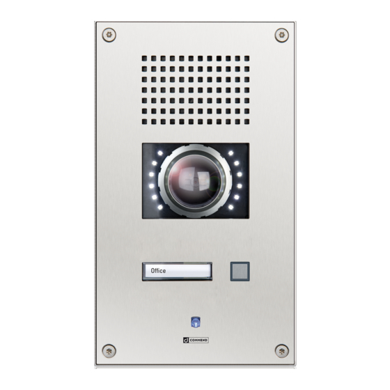
Commend SIP-WS 201VCA Kurzanleitung
Ip-sprechstelle
Verfügbare Sprachen
Verfügbare Sprachen
IP Stations SIP-WS 201VCA
Connection
OUT 2
OUT2 connection
OUT 2
OUT 2
OUT 2
OUT 1
Slot for inserting
button label
OUT 1
IP Uplink
IP Downlink
+ PoE
(AXIS Camera
+ PoE)
Camera illuminator control
The camera illuminator is connected via relay 2 (OUT 2) of the subscriber.
It is also possible to use relay 2 (OUT 2) as attendant contact, e.g. to switch on the camera
illuminator at initiation of a call.
For dimming the camera illuminator use the potentiometer
NOTE: It is only possible to use just one relay 2 (OUT 2) connection, i.e. either the screw
terminals or the connector (see connection diagram).
LED brightness
+
1
_
IN 1
MUTE
External
IN 2
GND
loudspeaker
module
LINE–
IN 3
GND
LINE+
Handset:
Microphone
Loudspeaker
on the camera board.
1
AXIS electronic module – Control button
Control button
In order to operate the control button, following steps must be performed:
• Loosen screw
(Torx T8)
1
• Turn safety lever
outwards
2
• Push control button
3
• Turn safety lever
back into its original position and tighten the screw
4
The control button can be used for reseting the camera to factory default settings:
• Disconnect power from the camera
• Press and hold the control button
• Keep the control button pressed until the LED indicator
• Release the control button. If the status LED
plete
Attention: After a reset the camera must be re-configured, as the camera image
would otherwise appear 180° upside down.
6
PWR
STAT
4
NET
3
2
2
1
5
and reconnect power
3
flashes amber
4
turns green the process is com-
4
1

Verwandte Anleitungen für Commend SIP-WS 201VCA


Inhaltszusammenfassung für Commend SIP-WS 201VCA
- Seite 3 IP-Sprechstelle SIP-WS 201VCA Anschluss AXIS-Elektronik-Modul – Steuertaste STAT OUT 2 LED Helligkeit – OUT2 Verbindung OUT 2 OUT 2 OUT 2 Steuertaste Einschuböffnung für OUT 1 Um die Steuertaste betätigen zu können müssen folgende Schritte durchgeführt Beschriftungsfelder OUT 1 werden: •...
- Seite 4 Dieses Gerät erfüllt die Anforderungen der EU-Richtlinie EMV-RL 2004/108/EG. zurückgesetzt und muss neu konfiguriert Hierfür trägt das Gerät die CE-Kennzeichnung. werden! Bitte bewahren Sie diese Beschreibung sorgfältig auf! Hinweis: Weitere Informationen bezüglich Installation und Einstellungen, entnehmen Sie dem AXIS-Manual „P3904-R“ . Type: D-BZ-SIP-WS 201VCA, Version: 2.1/0516 www.commend.com/sip...