Commend WS 201VICA Kurzanleitung
Ip-sprechstelle
Verfügbare Sprachen
Verfügbare Sprachen
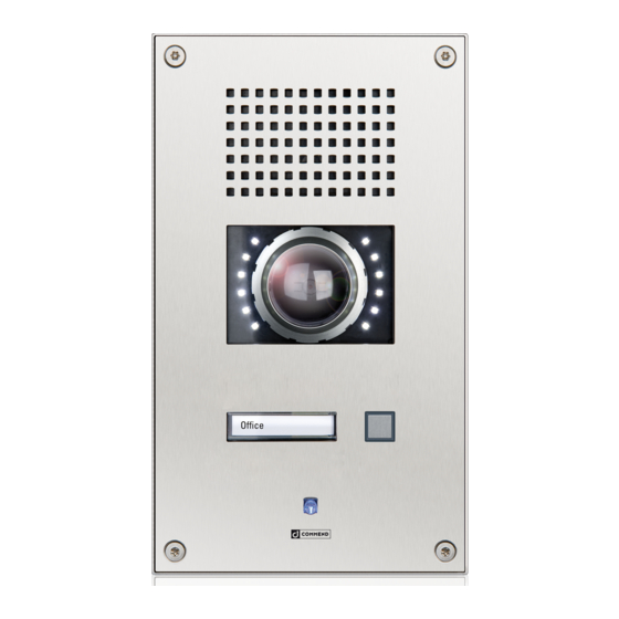
IP Stations WS 201VICA / WS 211VICA
Dimensions and recommended mounting height
Measurements in mm (in), not scale! Front panel thickness: 3 mm (0.12 in)
160 (6.3)
140 (5.5)
Cleaning instructions
The device may only be cleaned with cleaning agents for stainless steel. Do not use cleaning agents
containing chlorine or isopropanol.
Safety instructions
• This device may only be installed, replaced and maintained by trained and properly qualified
personnel (device class: ES1, PS2 as per IEC/EN 62368-1). The connectors are subject to possible
high transient voltage surges. The device is intended for appropriate installation in locations where
operating personnel cannot come into contact with uninsulated wires.
• Devices belonging to another earthing network must not be connected to the device's connectors.
• Do not install the device on unstable walls or on surfaces which cannot support the device's weight.
• Only accessories that comply with the device's technical specifications shall be used.
• All connected circuits shall fulfil the requirements for ES1 (cf. SELV acc. IEC/EN 60950-1) and PS2
(Limited Power Source) as per IEC/EN 62368-1.
• Use shielded Ethernet cables only.
• Before using the device, ensure all cables are correctly connected and not damaged.
• Disconnect the power supply (PoE) for any maintenance of the device.
• Allow the device to cool down completely before touching parts inside.
• Do not make any unauthorised modifications to the device.
Extent of supply
• Station
• Mounting screws (4 x Torx TR 25 security
countersunk screws, M5 x 10)
• Snap-on ferrite (to be attached to IP uplink
Ethernet cable)
• Short reference
Finished floor
Connection diagram
OUT 2
1
OUT 2
OUT 2
OUT 2
OUT 1
OUT 1
IP uplink
IP downlink
+ PoE
(Axis camera
Camera illumination and heating control
The camera illuminating and heating control are connected to the main board of the station
via the expansion bus. In CCT 800, the device is shown with an additional EB2E2A device.
Use OUT 1 on the EB2E2A to switch the camera illuminator on and off.
It is also possible to use OUT 1 as attendant contact, e.g. to switch on the camera illuminator
at call setup.
To dim the camera illuminator, use the potentiometer on the camera board.
Use OUT 2 on the EB2E2A to switch the camera heating on and off.
Note:
It is recommended to keep the heating on permanently to avoid condensation on the camera glass in
certain installation scenarios (e.g. inside metal columns). The same recommendation holds for envi-
ronments where the station is exposed to large fluctuations in temperature and to high humidity.
LED brightness
+
2
–
expansion bus
slot for inserting
button label
MUTE
IN 1
IN 2
GND
IN 3
LINE–
GND
LINE+
handset:
microphone
loudspeaker
+ PoE)
external
loudspeaker
module

Verwandte Anleitungen für Commend WS 201VICA


Inhaltszusammenfassung für Commend WS 201VICA
- Seite 3 IP-Sprechstelle WS 201VICA / WS 211VICA Anschlussdiagramm Abmessungen und empfohlene Montagehöhe Maße in mm, kein Maßstab! Frontplattenstärke: 3 mm Lieferumfang • Sprechstelle • Montageschrauben (4 x Torx-TR-25-Senkkopf- Sicherheitschrauben, M5 x 10) • Klappferrit (zur Montage auf dem Ethernet- Kabel „IP-Uplink“) •...
- Seite 4 Kabel verlaufen! Bei Nichtbeachtung kann die Axis Kamera beschädigt bzw. die Dichtheit der Elektronikgeräten (Richtlinie 2011/65/EU) Sprechstelle nicht gewährleistet werden. Technische Spezifikationen sind im entsprechenden Datenblatt zu finden. Bewahren Sie diese Beschreibung sorgfältig auf. Type: D-BZ-WS2X1VICA, Version: 2.4/0818 Commend International GmbH, Saalachstraße 51, A-5020 Salzburg – www.commend.com...