Commend SIP-WS 201V CA Kurzanleitung
Sip-sprechstelle
Verfügbare Sprachen
Verfügbare Sprachen
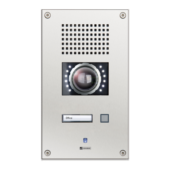
SIP station SIP-WS 201V CA
Dimensions and recommended mounting height
Measuring units in mm (in), not to scale! Front panel thickness: 3 mm (0.12 in)
160 (6.3)
140 (5.5)
Extent of supply
• Station
• Mounting screws (4 x Torx TR 25 security countersunk screws, M5 x 10)
• Snap-on ferrite (to be attached to IP uplink Ethernet cable)
• Short reference
Cleaning instructions
The device may only be cleaned with cleaning agents for stainless steel. Do not use cleaning agents
containing chlorine or isopropanol.
Safety instructions
• This device shall be installed or replaced by trained and qualified personnel only.
• Do not install the device on unstable walls or on surfaces which cannot support the device's weight.
• Only use recommended tools when installing the device.
• Only accessories that comply with the device's technical specifications shall be used.
• All connected circuits shall fulfil the requirements for Safety Extra Low Voltage (SELV) and Limited
Power Source (LPS) according to IEC/EN 60950-1.
• Use shielded Ethernet cables only.
• Before using the device, ensure all cables are correctly connected and not damaged.
• Disconnect the power supply (PoE or DC) for any maintenance of the device.
• Allow the device to cool down completely before touching parts inside.
• Do not make any unauthorised modifications to the device.
Connection diagram
Finished floor
Camera illumination
The camera illuminator is connected via relay 2 (OUT 2) of the subscriber. It is also possible to
1
use relay 2 (OUT 2) as attendant contact, e.g. to switch on the camera illuminator at call setup.
To dim the camera illuminator, use the potentiometer
Note:
The screw terminal and the connector of OUT 2 cannot be controlled separately (see connection
diagram).
OUT 2
1
OUT 2 connection
expansion jack
OUT 2
OUT 2
OUT 2
OUT 1
slot for inserting
button label
OUT 1
IN 1
IN 2
IN 3
GND
IP uplink
IP downlink
(e.g. WSHS 50P-JST)
+ PoE
(Axis camera
+ PoE)
LED brightness
+
2
–
external
loudspeaker module
MUTE
GND
factory
LINE–
reset
button
LINE+
handset
2
on the camera board.

Verwandte Anleitungen für Commend SIP-WS 201V CA


Inhaltszusammenfassung für Commend SIP-WS 201V CA
- Seite 3 SIP-Sprechstelle SIP-WS 201V CA Anschlussdiagramm Abmessungen und empfohlene Montagehöhe Maße in mm, kein Maßstab! Frontplattenstärke: 3 mm OUT 2 LED-Helligkeit – OUT-2-Verbindung Erweiterungsbuchse OUT 2 OUT 2 OUT 2 OUT 1 Einschuböffnung für Beschriftungsfelder OUT 1 Externes Lautsprechermodul Fertige Fussbodenoberfläche...
- Seite 4 Kabel verlaufen! Bei Nichtbeachtung kann die Axis Kamera beschädigt bzw. die Dichtheit der Technische Spezifikationen sind im entsprechenden Datenblatt zu finden. Bewahren Sie diese Beschreibung sorgfältig auf. Sprechstelle nicht gewährleistet werden. Type: D-BZ-SIP201VCA, Version: 2.4/0418 Commend International GmbH, Saalachstraße 51, A-5020 Salzburg – www.commend.com...