Commend SIP-WS 201V CA Kurzanleitung
Sip-sprechstelle
Verfügbare Sprachen
Verfügbare Sprachen
Quicklinks
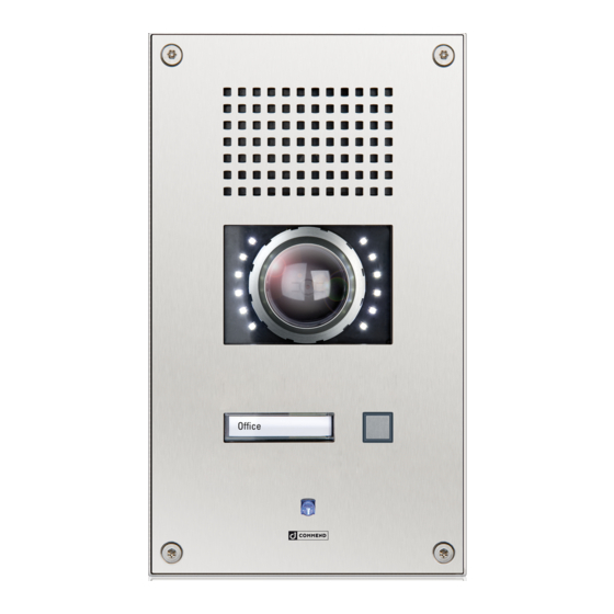
SIP station SIP-WS 201V CA
Dimensions and recommended mounting height
Measuring units in mm (in), not to scale! Front panel thickness: 3 mm (0.12 in)
160 (6.3)
140 (5.5)
Extent of supply
• SIP station
• Mounting screws (4 x Torx TR 25 security countersunk screws, M5x10)
• Short reference
Cleaning instructions
The device may only be cleaned with cleaning agents for stainless steel. Do not use cleaning agents
containing chlorine or isopropanol.
Safety warnings
• This device shall be installed or replaced by trained and qualified personnel only.
• Do not install the device on unstable walls or on surfaces, which cannot support the device's weight.
• Only use recommended tools when installing the device.
• Only accessories that comply with the device's technical specifications shall be used.
• All connected circuits shall fulfil the requirements for Safety Extra Low Voltage (SELV) and Limited
Power Source (LPS) according to IEC/EN 60950-1.
• Use shielded Ethernet cables only.
• Before using the device, ensure all cables are correctly connected and not damaged.
• Disconnect the power supply (PoE or DC) for any maintenance of the device.
• Allow the device to cool down completely before touching parts inside.
• Do not make any unauthorised modifications to the device.
Connection diagram
OUT 2
OUT 2
Finished floor
OUT 1
OUT 1
Camera illuminator control
The camera illuminator is connected via relay 2 (OUT 2) of the subscriber. It is also possible to use
relay 2 (OUT 2) as attendant contact, e.g. to switch on the camera illuminator at initiation of a call. The
dimming of the camera illuminator can be adjusted via the potentiometer
NOTE:
The screw terminal and the connector of OUT 2 cannot be controlled separately (see connection
diagram).
OUT 2
LED brightness
+
–
OUT 2 connection
Expansion jack
OUT 2
Slot for inserting
button label
IN 1
MUTE
IN 2
GND
IN 3
LINE–
GND
LINE+
Handset
IP uplink
IP downlink
(e.g. WSHS 50P-JST)
+ PoE
(Axis camera
+ PoE)
1
External
loudspeaker module
Factory
Reset
button
1
on the camera board.

Verwandte Anleitungen für Commend SIP-WS 201V CA


Inhaltszusammenfassung für Commend SIP-WS 201V CA
- Seite 3 SIP-Sprechstelle SIP-WS 201V CA Anschlussdiagramm Abmessungen und empfohlene Montagehöhe Maße in mm, kein Maßstab! Frontplattenstärke: 3 mm OUT 2 LED-Helligkeit – OUT-2-Verbindung Erweiterungsbuchse OUT 2 OUT 2 OUT 2 Fertige Fussbodenoberfläche Einschuböffnung für OUT 1 Beschriftungsfelder OUT 1 Externes Lautsprechermodul Lieferumfang •...
- Seite 4 • Beschränkung der Verwendung bestimmter gefährlicher Stoffe in Elektro- und Elektronikgeräten (Richtlinie 2011/65/EU) Technische Daten und Konfigurationsanweisungen sind im entsprechenden Manual zu finden. Bewahren Sie diese Beschreibung sorgfältig auf. Type: D-BZ-SIPWS201VCA, Version: 2.2/1117 Commend International GmbH, Saalachstraße 51, A-5020 Salzburg – www.commend.com/sip...