Gemü 4216 Original Einbau- Und Montageanleitung
Ventilanschaltung mit integriertem 5/2-wege vorsteuerventil atex

Verwandte Anleitungen für Gemü 4216


Inhaltszusammenfassung für Gemü 4216
- Seite 1 4216 Ventilanschaltung mit integriertem 5/2-Wege Vorsteuerventil ATEX Combi switchbox with integrated 5/2 way pilot valve ATEX ORIGINAL EINBAU- UND MONTAGEANLEITUNG INSTALLATION, OPERATING AND MAINTENANCE INSTRUCTIONS 4216...
-
Seite 2: Inhaltsverzeichnis
Verordnungen, Normen und Technische Daten Richtlinien gelten nur für Deutschland. Bei Fehlersuche / Einsatz der Ventilanschaltung in anderen Störungsbehebung Ländern sind die dort geltenden nationalen EU-Konformitätserklärung Regeln zu beachten. Wenn es sich um ATEX harmonisierte europäische Normen, 4216 2 / 36... -
Seite 3: Symbol- Und Hinweiserklärung
Die Nichtbeachtung der Sicherheitshinweise VORSICHT (OHNE SYMBOL) kann sowohl eine Gefährdung für Personen als auch für die Umwelt und die Möglicherweise gefährliche Situation! Ventilanschaltung zur Folge haben. Bei Nichtbeachtung drohen kann zum Verlust jeglicher Sachschäden. Schadensersatzansprüche führen. 4216 3 / 36... -
Seite 4: Bestimmungsgemäßer Gebrauch
Umgebung aufgebaut, angeschlossen und in Betrieb genommen werden. Das Fachpersonal muss stark ausgeprägte Kenntnisse über Die Ex ic Ventilanschaltung GEMÜ 4216 die Zündschutzart Eigensicherheit Ex ic der GEMÜ Gebr. Müller Apparatebau sowie über alle relevanten Vorschriften GmbH & Co. KG ist, in Verbindung mit und Verordnungen für Betriebsmittel im... -
Seite 5: Hinweise Für Den Einsatz In Feuchter Umgebung
10) Das Gerät darf nur im fertig montierten Zustand betrieben werden. 11) Trennen Sie Anschlussleitungen nie unter Spannung.12) Schließen Sie die Ventilanschaltung GEMÜ 4216 nur an eigensichere Stromkreise an, die mit einer EG-Baumusterprüfbescheinigung Hinweise zu Geräten zugelassen sind und die die Höchstwerte und Schutzsystemen zur des Sensors für Ui, Ii, Pi, Ci und Li nicht... -
Seite 6: Instandsetzung
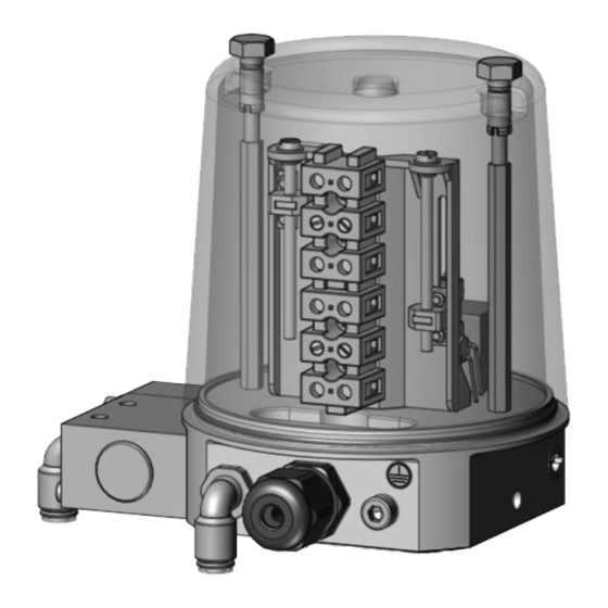
Passendes, funktionsfähiges und ¬ explosionsgefährdete Bereiche beachten. sicheres Werkzeug benutzen. Aufbau Instandsetzung Die Ventilanschaltung GEMÜ 4216 ist Bei Instandsetzung von geeignet für Hubventile mit Linearantrieb bis explosionsgeschützten Geräten die zu 50 mm Hub (Betätigungsweg). entsprechenden nationalen Bestimmungen Das Gehäuse ist in stabilem, transparenten beachten. -
Seite 7: Montage
Abdeckkappe A bzw. optische Stellungs- ¬ anzeige B, C vom Antriebsoberteil entfernen. Art des Anbausatzes prüfen: ¬ - Anbausatz mit Innen- oder Außengewinde: Montage siehe Kapitel 4.2.1 oder 4.2.2. - Anbausatz ohne Gewinde: Montage siehe Kapitel 4.3. 4216 7 / 36... -
Seite 8: Montage Des Anbausatzes Mit Gewinde
Mutter J gegen das Antriebsoberteil ¬ kontern. Gewindedichtring K nur optional für ¬ Antriebe mit Steuerfunktion 2 und 3 verwenden. Montage des Anbausatzes ohne Gewinde Abdeckkappe A vom Antriebsoberteil ¬ entfernen. Führungsstück F mit Schlüsselfläche ¬ einschrauben. 4216 8 / 36... -
Seite 9: Vorbereitung Der Ventilanschaltung
¬ einführen. Spindel des Anbausatzes S mit ¬ geeignetem Werkzeug T mit Gefühl bis zum Anschlag einschlagen. Muttern G lösen und im Deckel H ¬ belassen. Deckel H abheben. ¬ Führungsstück F mit Schlüsselfläche ¬ einschrauben. 4216 9 / 36... -
Seite 10: Montage Der Ventilanschaltung
Gewindestift K lösen (nicht ¬ herausdrehen). Unterteil der Ventilanschaltung auf ¬ Führungsstück F aufstecken. Vorsicht beim Aufstecken, damit Schalter nicht durch Schaltnocken beschädigt werden! Ventilanschaltung in gewünschte ¬ Anschlussrichtung drehen und Position mit Gewindestift K fixieren. 4216 10 / 36... -
Seite 11: Einstellung Der Schaltpositionen
Mit der linken Schraube L den ¬ Schalter N bis zur gewünschten Position verschieben. Endschalter AUF Magnetventil Darauf achten, dass die ¬ Schaltfläche komplett von Endschalter ZU der Schaltnocke Q überdeckt wird, um ein eindeutiges Schaltsignal zu erhalten. 4216 11 / 36... -
Seite 12: Anschluss Des Potentialausgleichs
Verbindungen gegen Selbstlockern 4.10 Pneumatische Anschlüsse ¬ sichern. Abschluss der Montage Wichtig: Maximalen Steuerdruck des pneumatischen Ventilantriebs beachten! Druckluftversorgung: 2...10 bar. Zeichenerklärung 1 (P) Zuluft 2 (A) Ausgang Stf. 1, 2, 3 Abluft Stf. 1, 2, 3 4216 12 / 36... -
Seite 13: Demontage
Versandpapieren beiliegt. Gefahr der statischen Aufladung bei Nur wenn diese Erklärung unsachgemäßer Reinigung! vollständig ausgefüllt ist, wird die Bei Nichtbeachtung entsteht eine Rücksendung bearbeitet! Zündquelle. Ventilanschaltung nur mit antistatischen ¬ Mitteln reinigen! 4216 13 / 36... -
Seite 14: Hinweise
Hinweis zur Mitarbeiterschulung: Zur Mitarbeiterschulung nehmen Sie bitte über die Adresse auf der letzten Seite Kontakt auf. Im Zweifelsfall oder bei Missverständnissen ist die deutsche Version des Dokuments ausschlaggebend! 10 Maße Alle Angaben in mm 124,3 4216 14 / 36... -
Seite 15: Technische Daten
II 2 G/D EEx e II IP 65 EG-Baumusterprüfbescheinigung PTB 99 ATEX 3101 X Klemmleiste ATEX Kennzeichnung II 2 G Ex e II EG-Baumusterprüfbescheinigung PTB 99 ATEX 3117 U Boosterventil ATEX Kennzeichnung II 2 G / Dc T6 EG-Baumusterprüfbescheinigung 4216 15 / 36... -
Seite 16: Fehlersuche / Störungsbehebung
Kabel ragen über den Rand des Unterteils Kabelverlegung prüfen, ggf. Kabel einkürzen Mutter wieder einlegen, Gewindestift K eindrehen Gewindestift K Gewindestift K zu weit herausgedreht, (Gewindestift K bei der Montage nur ohne Funktion Mutter fiel heraus lösen, nicht herausdrehen) 4216 16 / 36... -
Seite 17: Eu-Konformitätserklärung Atex
Fritz-Müller-Straße 6-8 D-74653 Ingelfingen erklären, dass das unten aufgeführte Gerät die Anforderungen der Richtlinie 2014/34/EU zur bestimmungsgemäßen Verwendung in explosionsgefährdeten Bereichen erfüllt. Benennung des Gerätes - Typenbezeichnung Ventilanschaltung GEMÜ 4216 Kennzeichnung: 4216000Z05210102001C132AT51 4216000Z05210102001C132A4U7 Erläuterungen: Besondere Bedingungen und Einsatzgrenzen siehe Dokumentation und / oder EG-Baumusterprüfbescheinigungen... - Seite 34 4216 34 / 36...
- Seite 35 4216 35 / 36...
- Seite 36 GEMÜ Gebr. Müller Apparatebau GmbH & Co. KG · Fritz-Müller-Str. 6-8 · D-74653 Ingelfingen-Criesbach Telefon +49(0)7940/123-0 · Telefax +49(0)7940/123-192 · info@gemue.de · www.gemu-group.com...