Inhaltsverzeichnis
Werbung
Quicklinks
INSTRUCTIONS AND ILLUSTRATED PARTS MANUAL
BETRIEBSANLEITUNG UND ILLUSTRIERTES TEILEVERZEICHNIS
81500B2
81500BA2
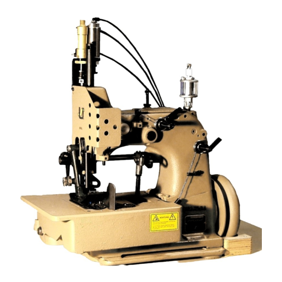
MIRAKLES SINGLE NEEDLE, SINGLE, TWO OR THREE THREAD
OVERSEAMING MACHINES
MIRAKLES EINNADEL-, EIN-, ZWEI- ODER DREIFADEN-
ÜBERWENDLICH-NÄHMASCHINEN
MANUAL NO. / KATALOG NR. G234-GR
FOR STYLES / FÜR TYPEN
81500A, B, B1H, B2, BA, BA1H, BA2, C, E
07/01/15
Werbung
Inhaltsverzeichnis

Verwandte Anleitungen für Union Special 81500B2


Inhaltszusammenfassung für Union Special 81500B2
- Seite 1 INSTRUCTIONS AND ILLUSTRATED PARTS MANUAL BETRIEBSANLEITUNG UND ILLUSTRIERTES TEILEVERZEICHNIS 81500B2 81500BA2 MIRAKLES SINGLE NEEDLE, SINGLE, TWO OR THREE THREAD OVERSEAMING MACHINES MIRAKLES EINNADEL-, EIN-, ZWEI- ODER DREIFADEN- ÜBERWENDLICH-NÄHMASCHINEN MANUAL NO. / KATALOG NR. G234-GR FOR STYLES / FÜR TYPEN 81500A, B, B1H, B2, BA, BA1H, BA2, C, E...
- Seite 2 81500 SERIES MACHINES TEILEVERZEICHNIS FÜR MASCHINENKLASSE 81500 First Edition Copyright 2006 Erste Auflage © 2006 Weltweit beanspruchte Union Special GmbH Union Special GmbH Rights Reserved in All Coun- Rechte tries PREFACE VORWORT This catalog has been prepared to guide you while...
-
Seite 3: Inhaltsverzeichnis
TABLE OF CONTENTS INHALTSVERZEICHNIS PAGE / SEITE SAFETY RULES 4 - 5 SICHERHEITSHINWEISE IDENTIFICATION OF MACHINES BEZEICHNUNG DER MASCHINEN APPLICATION OF THIS INSTRUCTION MANUAL BENÜTZUNG DIESER BETRIEBSANLEITUNG STYLES OF MACHINES 6 - 7 MASCHINENTYPEN INSTALLATION 8 – 11 AUFSTELLUNG LUBRICATING 12 - 13 ÖLEN NEEDLES... -
Seite 4: Safety Rules
SAFETY RULES SICHERHEITSHINWEISE Before putting the machines described in this manual Lesen Sie vor Inbetriebnahme der in diesem Katalog into service, carefully read the instructions. The start- beschriebenen Maschinen die Betriebsanleitung ing of each machine is only permitted after taking sorgfältig. -
Seite 5: Identification Of Machines
IDENTIFICATION OF MACHINES BEZEICHNUNG DER MASCHINEN Each UNION SPECIAL 81500 series machine is identified Jede UNION SPECIAL 81500 Maschine hat eine in das by a style number, which is stamped on the style plate Typenschild eingeprägte Typennummer, das rechts vor- affixed to the right front of machine. -
Seite 6: Styles Of Machines
STYLES OF MACHINES MASCHINENTYPEN „MIRAKLES“ single needle, single two and three thread „MIRAKLES“ Einnadel-, Ein-, Zwei- und Dreifaden-Überwend- overseamers with 71 mm (2 51/64 in.) needle throw. Manual lichmaschinen mit 71 mm Nadelhub. Manuelle Schmierung. lubrication. 81500A: Two thread machine. For even matched seaming 81500A: Zweifaden-Maschine. - Seite 7 Führungen für Dichtkordel von oben und / oder unten zum Abdichten der Nadeleinstiche der linken Nadel. 81500B2: Same as 81300B1H, but without any thread 81500B2: Wie 81500B1H, jedoch ohne jeglichen Faden- chain cutter.
-
Seite 8: Installation
INSTALLATION AUFSTELLUNG... - Seite 9 INSTALLATION (continued) AUFSTELLUNG (Fortsetzung) Unpack the sewing machine and the accessories. Packen Sie die Nähmaschine und das Zubehör aus. Mount the base plate (A, Fig. 1) with four screws, nuts Montieren Sie die Grundplatte (A, Fig. 1) mit vier and washers (B) in the provided holes on the table Schrauben, Muttern und Scheiben (B) in den dafür board.
- Seite 11 INSTALLATION (continued) AUFSTELLUNG (Fortsetzung) 11. Hook the lifter chain to the lifter lever of the sewing 11. Hängen Sie die Lifterkette am Lifterhebel der Näh- machine and to the small treadle on the sewing maschine und am kleinen Pedal des Nähtisches ein. table.
-
Seite 12: Lubricating
LUBRICATING ÖLEN Turn off main power switch before lubricating! Schalten Sie vor dem Ölen den Haupt- When using clutch motors with or without schalter aus! Beim Gebrauch von Kupp- actuation lock wait until motor has com- lungsmotoren mit oder ohne Betätigungs- pletely stopped. -
Seite 13: Needles
Zum Ölen empfehlen wir "Mobil Oil DTE Medium" oder ein or equivalent, which can be purchased from UNION gleichwertiges Öl, das von UNION SPECIAL in 1/2 Liter Be- SPECIAL in 1/2 liter containers under part number hältern unter der Teilnummer G28604L oder in 5 Liter Behäl- G28604L or in 5 liter containers under part number tern unter der Teilnummer G28604L5 bezogen werden kann. -
Seite 14: Threading Diagram
THREADING DIAGRAM EINFÄDELANLEITUNG CAUTION! Turn of f main power switch before ACHTUNG! Schalten Sie vor dem Einfädeln den threading! When using clutch motors with Hauptschalter aus! Warten Sie bei or without actuation lock wait until the Kupplungsmotoren mit oder ohne motor has completely stopped! Betätigungssperre den Stillstand des Motors ab! - Seite 15 THREADING DIAGRAM EINFÄDELANLEITUNG CAUTION! Turn of f main power switch before ACHTUNG! Schalten Sie vor dem Einfädeln den threading! When using clutch motors with Hauptschalter aus! Warten Sie bei or without actuation lock wait until the Kupplungsmotoren mit oder ohne motor has completely stopped! Betätigungssperre den Stillstand des Motors ab!
-
Seite 16: Operating Instructions
OPERATING INSTRUCTIONS BEDIENUNGSANLEITUNG THREADING EINFÄDELN CAUTION! Turn off main power switch before ACHTUNG! Schalten Sie vor dem Einfädeln den Haupt- threading! When using clutch motors schalter aus! Warten Sie bei Kupplungsmotoren with or without actuation lock wait until mit oder ohne Betätigungssperre den Stillstand the motor has stopped! des Motors ab! Styles 81500A, B, B1H, B2, BA, BA1H, BA2 and 81500E... -
Seite 17: Fadenspannung
NEEDLE THREAD TAKE-UP NADELFADENABZUG Basically the needle thread take-up roller (B, Figs. 5 and Standardmäßig wird die Nadelfadenabzugsrolle (B, Fig. 5A), located left on the upper bed casting under the face 5 und 5A), links am Gehäuseoberteil unter dem Stirn- cover, is set as low as possible. -
Seite 18: Einstellbare Kantenführung
Set the edge guide (A, Figs. 6 and 6 A) laterally as Stellen Sie die Kantenführung (A, Fig. 6 und 6A) seitlich so close as possible to the presser foot, without contacting dicht wie möglich an den Drückerfuß, ohne diesen zu it. -
Seite 19: Maintenance
MAINTENANCE WARTUNG CAUTION! Turn off main power switch before doing ACHTUNG! Schalten Sie vor Wartungsarbeiten den maintenance works! When using clutch Hauptschalter aus! Warten Sie bei Kupp- motors with or without actuation lock wait lungsmotoren mit oder ohne Betäti- until the motor has stopped! gungssperre den Stillstand des Motors ab! LUBRICATING AND CLEANING ÖLEN UND REINIGEN... -
Seite 20: Instructions For Mechanics
INSTRUCTIONS FOR MECHANICS MECHANIKERANLEITUNG Observe the SAFETY RULES when making Beachten Sie die SICHERHEITSHINWEISE, wenn adjustments! sie Einstellarbeiten machen! Before adjusting the machine remove the face cover Entfernen Sie vor dem Einstellen der Maschine den Stirn- and the finger guard left on the machine head, the deckel und den Fingerabweiser links am Maschinenkopf, upper feed dog, the presser foot, the cloth plate with den oberen Transporteur, den Drückerfuß, die Stoffplatte... -
Seite 22: Einstellung Der Nadelstangenhöhe
SETTING THE HEIGHT OF THE NEEDLE BAR EINSTELLUNG DER NADELSTANGENHÖHE Rotate handwheel in operating direction until the point Drehen Sie das Handrad in Nährichtung bis die Spitze of lower looper (A, Fig. 9) or the point of lower spreader des Untergreifers (A, Fig. 9) oder die Spitze des unteren (A, Fig. - Seite 23 Fig. 10 Fig. 11 Fig. 11A Fig. 11B Fig. 11C Fig. 12...
-
Seite 24: Einstellung Des Obergreifers
Rotate handwheel in operating direction until the Drehen Sie das Handrad in Nährichtung bis der obere upper spreader is in its extreme right lower end position. Blindgreifer in seiner äußerst rechten unteren Endstellung The upper spreader should not contact any machine ist. - Seite 26 In the extreme left upper end position of upper looper In der äußerst linken oberen Endstellung des Obergreifers (A, Fig. 11 B), the distance between the left edge of (A, Fig. 11 B) muß der Abstand zwischen der linken Kante looper eye and the center of needle (N) should be 6 des Greiferöhrs und der Nadelmitte (N) 6 mm betragen.
-
Seite 27: Stichplattenstütze Und Winkel Für Vorderen Nadel- Anschlag
SETTING THE LOWER FEED DOG EINSTELLUNG DES UNTEREN TRANSPORTEURS The lower feed dog (A, Fig. 15) should center laterally in Der untere Transporteur (A, Fig. 15) muß in den Schlitzen the slots of throat plate (B). If an adjustment is necessary der Stichplatte (B) seitlich vermittelt sein. -
Seite 29: Obertransporteurbewegung
For setting the upper feed dog with respect to the slot Zum Einstellen des Obertransporteurs im Bezug zu den ends in the presser foot and the tooth spaces of the Schlitzenden im Drückerfuß und zu den Zahnlücken des lower feed dog, loosen screw (D, Fig. 18) and turn drive unteren Transporteurs, lösen Sie die Schraube (D, Fig. -
Seite 30: Changing Stitch Length
The presser foot lift is limited with the upper stop collar Der Hub des Drückerfußes wird mit dem Anschlag-Stell- (D, Fig. 23) on the right presser bar. When the needle is ring (D, Fig. 23) oben auf der rechten Drückerfußstange in its lowest position and the presser foot is lifted with begrenzt. -
Seite 31: Einstellung Der Zeitrelais Im Steuergerät Des Heissschneiders Für Fadenkette
SETTING THE TIME RELAYS IN THE SWITCH BOX OF HOT EINSTELLUNG DER ZEITRELAIS IM STEUERGERÄT DES THREAD CHAIN CUTTER HEISSSCHNEIDERS FÜR FADENKETTE Styles 81500B1H, BA1H Klassen 81500B1H, BA1H The switch box includes two time relays marked K2T Der Schaltkasten beinhaltet zwei Zeitrelais, die mit K2T and K4T. -
Seite 32: Ordering Wear And Spare Parts
ORDERING WEAR AND SPARE PARTS BESTELLUNG VON VERSCHLEISS- UND ERSATZTEILEN The following section of this manual simplifies ordering Der folgende Teil dieses Handbuches vereinfacht die wear and spare parts. Exploded views of various Bestellung von Verschleiß- und Ersatzteilen. Explosi- sections of the mechanism are shown so that the parts onszeichungen der einzelnen Gruppen des Mechanis- may be seen in their actual position in the sewing mus zeigen die Lage der Einzelteile in der Nähmaschi-... -
Seite 33: Views And Description Of Parts
VIEWS AND DESCRIPTION OF PARTS DARSTELLUNGEN UND TEILEBESCHREIBUNGEN... - Seite 35 BUSHING, SIGHT FEED OILER, OILERS BUCHSEN, TROPFÖLER Ref. No. Part No. Description Beschreibung Amt. Req. Pos. Nr. Teil Nr. Anzahl 80862 Presser Bar Bushing Buchse für Drückerfußstange 81373A Needle Bar Bushing Buchse für Nadelstange GR-80293A Oil Distributor Ölverteiler 22894K Spot Screw, headless Gewindestift mit Spitze 22894J Set Screw...
-
Seite 37: Cloth Plate, Base Plate, Guards And Miscellaneous Covers
CLOTH PLATE, BASE PLATE, GUARDS AND MISCELLANEOUS COVERS STOFFPLATTE, GRUNDPLATTE, SCHUTZTEILE UND VERSCHIEDENE ABDECKUNGEN Ref. No. Part No. Description Beschreibung Amt. Req. Pos. Nr. Teil Nr. Anzahl 80673CB Needle Bar Guard Nadelstangenschutz 80888 Arm Cover Armdeckel 80764 T-Screw Knebelschraube 35733B Knurled Nut Rändelmutter 81387... -
Seite 39: Thread Tensions And Thread Guide Parts Fadenspannungen Und Fadenführungsteile
THREAD TENSIONS AND THREAD GUIDE PARTS FADENSPANNUNGEN UND FADENFÜHRUNGSTEILE Amt. Req. Part No. Ref. No. Description Beschreibung Anzahl Teil Nr. Pos. Nr. Tension Post for 81500A, B, BA HS106 Spannungsbolzen für 81500A, B, BA 81500C 81500C 81500E 81500E Tension Post Ferrule for 80669B Hülse für Spannungsbolzen für 81500A, B, BA... -
Seite 41: Thread Tensions And Thread Guide Parts Fadenspannunen Und Fadenführungsteile
THREAD TENSIONS AND THREAD GUIDE PARTS FADENSPANNUNEN UND FADENFÜHRUNGSTEILE Amt. Req. Part No. Ref. No. Description Beschreibung Anzahl Teil Nr. Pos. Nr. Ref. Nos. 1 - 32 see page 39 Pos. Nrn. 1 - 32, siehe Seite 39 81256A Thread Sleeve for looper thread Fadenhülse für Greiferfäden for 81500A, B, BA für 81500A, B, BA... -
Seite 43: Needle Bar, Needle Lever, Crankshaft, Handwheel Nadelstange, Nadelhebel, Kurbelwelle, Handrad
NEEDLE BAR, NEEDLE LEVER, CRANK SHAFT, HANDWHEEL NADELSTANGE, NADELHEBEL, KURBELWELLE, HANDRAD Description Ref. No. Part No. Amt. Req. Beschreibung Pos. Nr. Teil Nr. Anzahl 81317 Needle Bar Nadelstange 80620H Sleeve Spannhülse Collar for 81500A Stellring für 81500A 81566 22536 Screw Schraube 81518 Needle Holder... -
Seite 45: Looper Drive Mechanism Greiferantriebsmechanismus
LOOPER DRIVE MECHANISM GREIFERANTRIEBSMECHANISMUS Amt. Req. Part No. Ref. No. Beschreibung Description Anzahl Teil Nr. Pos. Nr. G29442L Upper Spreader / Looper Drive Exzenter für oberen Blindgreifer-/ Eccentric Assembly Greiferantrieb, komplett G29442LA Lower Looper Drive Eccentric Assy. Exzenter für Untergreiferantrieb, komplett 80236 Connection Verbindungslager... -
Seite 47: Upper And Lower Feed Drive Mechanism Ober- Und Untertransport-Antriebsmechanismus
UPPER AND LOWER FEED DRIVE MECHANISM OBER- UND UNTERTRANSPORT-ANTRIEBSMECHANISMUS Ref. No. Part No. Description Beschreibung Amt. Req. Pos. Nr. Teil Nr. Anzahl 80740 Drive Shaft Antriebswelle 80791 Drive Lever Antriebshebel BP108 Hex. Head Cap Screw Sechskantschraube 52951C Washer Scheibe 51147 Collar Stellring Set Screw... -
Seite 49: Presser Bars, Presser Bar Springs And Presser Foot Lifter Lever
PRESSER BARS, PRESSER BAR SPRINGS AND PRESSER FOOT LIFTER LEVER DRÜCKERFUSSSTANGEN, FEDERN FÜR DRÜCKERFUSSSTANGEN UND DRÜCKERFUSSLIFTERHEBEL Ref. No. Part No. Description Beschreibung Amt. Req. Teil Nr. Anzahl Pos. Nr. 80648 Lifter Lever Lifterhebel Shoulder Screw for lifter lever Ansatzschraube für Lifterhebel 80649 Spring Feder... -
Seite 51: Electro-Pneumatic Parts Kit For Upper Feed Pressure And Lifter For 81500B1H, B2, Ba1H, Ba2 With
Anzahl 1-33,35 A10455-813E Electro-Pneumatic Parts Kit for upper Elektropneumatik-Teilesatz für Ober- feed pressure and lifter for transportdruck und -liftung für 81500B2, BA2 81500B2, BA2 1-22, A10455H813E Electro-Pneumatic Parts Kit for upper Elektropneumatik-Teilesatz für Ober- 24-35 feed pressure, lifter and hot thread... -
Seite 53: Control For Electro-Pneumatic Hot Thread Chain Cutter For 81500B1H, Ba1H
CONTROL FOR ELECTRO-PNEUMATIC HOT THREAD CHAIN CUTTER FOR 81500B1H, BA1H STEUERUNG FÜR ELEKTROPNEUMATISCH BETÄTIGTEN FADENKETTEN-HEISSSCHNEIDER FÜR 81500B1H, BA1H Amt. Req. Ref. No. Part No. Description Beschreibung Anzahl Pos. Nr. Teil Nr. 99712HAE Control for Hot Thread Chain Cutter Steuerung für Fadenketten-Heißschneider 134001 PA Tube 6 x 4;... - Seite 55 CONTROL FOR ELECTRO-PNEUMATIC HOT THREAD CHAIN CUTTER 81500B1H, BA1H STEUERUNG FÜR ELEKTROPNEUMATISCH BETÄTIGTEN FADENKETTEN-HEISSSCHNEIDER 81500B1H, BA1H Amt. Req. Ref. No. Part No. Description Beschreibung Anzahl Pos. Nr. Teil Nr. Control Box of hot thread chain Steuergerät des Heißschneiders für cutter 999-315B Fadenkette 999-315B 90242TA Control Board...
-
Seite 57: Electro-Pneumatic Hot Thread Chain Cutter For 81500B1H, Ba1H
ELECTRO-PNEUMATIC HOT THREAD CHAIN CUTTER FOR 81500B1H, BA1H ELEKTROPNEUMATISCH BETÄTIGTER FADENKETTEN-HEISSSCHNEIDER FÜR 81500B1H, BA1H Amt. Req. Ref. No. Part No. Description Beschreibung Anzahl Pos. Nr. Teil Nr. 99712H813 El.-Pneum.Hot Thread Chain Cutter El.-pneum.Fadenketten-Heißschneider 999-315B Hot Cutter for thread chain with Heißschneider für Fadenketten mit control box Steuergerät... -
Seite 59: Sewing Parts; Styles 81500A, B, B1H, B2, Ba, Ba1H, Ba2 And 81500C
SEWING PARTS, STYLES 81500A, B, B1H, B2, BA , BA1H, BA2 AND 81500C NÄHTEILE, TYPEN 81500A, B, B1H, B2, BA, BA1H, BA2 UND 81500C Amt. Req. Ref. No. Part No. Description Beschreibung Anzahl Pos. Nr. Teil Nr. 81326 Feed Dog, upper Transporteur, oben Schraube 136A... -
Seite 61: Sewing Parts, Style 81500E Nähteile, Typ 81500E
SEWING PARTS, STYLE 81500E NÄHTEILE, TYP 81500E Amt. Req. Ref. No. Part No. Description Beschreibung Anzahl Pos. Nr. Teil Nr. 81326 Feed Dog, upper Transporteur, oben 136A Screw Schraube 81530E Presser Foot Drückerfuß 22596B Screw Schraube 81597A19 Presser Foot Tongue, marked "WL-19" Drückerfußzunge, gezeichnet "WL-19"... -
Seite 63: Accessories Zubehör
ACCESSORIES ZUBEHÖR Ref. No. Part No. Amt. Req. Description Beschreibung Pos. Nr. Teil Nr. Anzahl 93065B1 Thread Stand, 1 Cone for 81500E Fadenständer, 1-teilig für 81500E 93065B2 Thread Stand, 2 Cones Fadenständer, 2-teilig 93065B3 Thread Stand, 3 Cones Fadenständer, 3-teilig 93065BA Base Fuß... - Seite 65 ACCESSORIES ZUBEHÖR Ref. No. Part No. Amt. Req. Description Beschreibung Pos. Nr. Teil Nr. Anzahl 93065D3WS Thread Stand, 3 Cones Fadenständer, 3-teilig 93065D4WS Thread Stand, 4 Cones Fadenständer, 4-teilig 93065D5WS Thread Stand, 5 Cones Fadenständer, 5-teilig 93065DA Thread Stand Base Fadenständerfuß...
-
Seite 66: Numerical Index Of Parts Numerisches Teileverzeichnis
NUMERICAL INDEX OF PARTS NUMERISCHES TEILEVERZEICHNIS Part No. Page Part No. Page Part No. Page Part No. Page Teil Nr. Seite Teil Nr. Seite Teil Nr. Seite Teil Nr. Seite 1021U ... 65 22894AD ... 39, 41, 43, 47 80620H ... 43 80858AX ... - Seite 67 NUMERICAL INDEX OF PARTS NUMERISCHES TEILEVERZEICHNIS Part No. Page Part No. Page Part No. Page Part No. Page Teil Nr. Seite Teil Nr. Seite Teil Nr. Seite Teil Nr. Seite 81503G ... 61 93065DE ... 65 99711MH ... 57 G29099Q ... 47 81505A ...
- Seite 68 WORLDWIDE SALES AND SERVICE WELTWEITER VERKAUF UND KUNDENDIENST Union Special maintains sales and service facilities throughout the world. These offices will aid you in the selection of the right sewing Hong Kong, China equipment for your particular operation. Union Special represen-...