Herunterladen Inhalt Inhalt Diese Seite drucken
Inhaltsverzeichnis

Werbung

Verfügbare Sprachen

Verfügbare Sprachen

3CCD Digital Camera
3CCD Digitale Kamera
3CCD Caméra numérique
KY-F75
For Customer Use:
Enter below the Serial No. which is
located on the unit. Retain this
information for future reference.
Model No. KY-F75
Serial No.
INSTRUCTIONS
BEDIENUNGSANLEITUNG
MANUEL D'INSTRUCTIONS
Illustration with optional lens attachment.
This instruction book is made from 100%
recycled paper.
Introduction
Preparations
Recording
Settings
Others
LWT0059-001B

Werbung

Inhaltsverzeichnis
loading

Inhaltszusammenfassung für JVC KY-F75

  • Seite 1 Illustration with optional lens attachment. For Customer Use: Enter below the Serial No. which is located on the unit. Retain this information for future reference. This instruction book is made from 100% Model No. KY-F75 recycled paper. Serial No. LWT0059-001B...
  • Seite 2: Important Safeguards

    These are general IMPORTANT SAFEGUARDS and certain items may not apply to all appli- ances. IMPORTANT SAFEGUARDS 1. Read all of these instructions. 2. Save these instructions for later use. 3. All warnings on the product and in the operating instructions should be adhered to. 4.
  • Seite 3 13. Follow all warnings and instructions marked on the appliance. 14. Do not overload wall outlets and extension cords as this can result in fire or electric shock. 15. Never push objects of any kind into his appliance through cabinet slots as they mat touch dangerous voltage points or short out parts that could result in a fire or electric shock.
  • Seite 4 +30-210-4832855 Bruxelles 1070 Brussel, Belgium tel: +32(02)529-4211 7. JVC Professional Europe Ltd. Leiden, Nederland JVC Plein, De Heyderweg 2, 2314 XZ Leiden, Nederland tel: +31(071)545-3333 JVC Professional Products Company 1700 Valley Road, Wayne, NJ 07470 USA HEADQUARTERS tel: +1(973)317-5000 JVC Canada Inc.
  • Seite 5: Safety Precautions

    SAFETY PRECAUTIONS FOR USA AND CANADA For Sweden VARNING This symbol indicates type B Explosionsfara vid felaktigt batteribyte. equipment classified in accor- Använd samma batterityp eller en ekvivalent typ dance with IEC Publication. som rekommenderas av apparattillverkaren. 601-1 Safety of medical elec- Kassera använt batteri enligt fabrikantens trical equipment.
  • Seite 6 Thank you for purchasing the JVC KY-F75 The instructions are given in three languages: Digital Camera. English from page E2 to E47 These instructions are for KY-F75U. German from page G2 to G47 French from page F2 to F47 SAFETY PRECAUTIONS...
  • Seite 7 In such case, please keep the apparatus away from the sources of the disturbance. KY-F75 is designed and operated for non patient equipment when used in the hospi- tal or other medical environments. KY-F75 and AA-P700EG are tested and complied in accordance with IEC 601-1 safety standards.
  • Seite 8: Inhaltsverzeichnis

    Contents 1. Introduction 4. Settings Features ............ 5 Opening and closing Accessories and attachments ....5 the Settings screen ......... 24 Cautionary notes for the correct usage of Exposure settings screen ......26 this product ..........6 White balance settings screen ....30 Part names and their functions ....
  • Seite 9: Introduction

    1. Introduction Features ● The KY-F75 is a digital camera employing three 1/2” CCD with 1.45 million effective pixels. ● Output of 1360 × 1024-pixel digital video signal possible. ● Built-in DSP for real-time processing of the video signal that is output as a 7.5 frames-per- second RGB digital signal enables real-time transfer to personal computer by means of IEEE1394 host adapter.
  • Seite 10: Cautionary Notes For The Correct Usage Of This Product

    • Do not leave the product where it is subject to radiation or X-rays or in locations where corrosive gasses are generated. Cleaning When clean the equipment please use dry cleaning cloth or wet cleaning cloth with small amount of alcohol. Do not spill any liquid into KY-F75.
  • Seite 11: Part Names And Their Functions

    Part names and their functions [Front and bottom] ³ ³ Lens mount ¿ Screw holes for mounting the camera (1/4-inch) Although the lens mount conforms to the type C mount lens, there are restrictions Used when mounting the camera to a fixer on the lenses that can be used.
  • Seite 12: Pin Configurations Of Connectors

    1. Introduction (continued) Part names and their functions (continued) [Rear] [REMOTE] terminal (Metal 10-pin, female) Used to connect external devices such as a trigger switch or flash unit. Pin configurations of connectors ( page LENS IEEE1394 REMOTE [POWER] indicator Lights when power is supplied to the cam- DC IN era.
  • Seite 13 12V output (only when power LENS terminal (Metal 12-pin, female) is supplied from AC adapter) CAUTION • Consult your JVC dealer concerning the re- mote terminal connection. • Remote cable must use shielded cable. Outer shield of remote cable must to connect 10-pin connector outer metal shell.
  • Seite 14: Preparations

    The power to the KY-F75 can be supplied through the IEEE1394 connector of the computer. Caution When the KY-F75 is supplied with power though the IEEE1394 cable, make sure that the capacity on the supplying side is sufficient to meet the consumption by the KY-F75 (approximately 600 mA in the case of DC 12 V).
  • Seite 15 When the motorized lens is used, the separately sold AC Adapter AA-P700 should be used to supply the power to the camera. Connect the [DC IN] connector on the KY-F75 to the AA-P700 using the DC power cable. Attach the clamp filter supplied with the KY-F75 to the DC power cable.
  • Seite 16: Preparing The Computer

    2. Preparations (continued) Preparing the computer The camera image is displayed on the computer screen and the KY-F75 is controlled from the computer. There are restrictions on the computers that can be connected. See [Specifications for connectable computer] on page E45.
  • Seite 17: Installation Procedure

    [KY-LINK] application software. ● For how to install the KA-FW4IU, refer to the instructions for the KA-FW4IU. Also, for installation of the driver, see the Readme file on the CD-ROM supplied with the KY-F75. Install of the [KY-LINK] application software as follows.
  • Seite 18: Connection To Computer

    However, the following precautions must be adhered to. Precautions on power supply • When supplying the KY-F75 with power though the IEEE1394 cable, make sure that the capacity on the supplying side is sufficient to meet the consumption by the KY-F75 (approximately 600 mA in the case of DC 12 V).
  • Seite 19: Mounting And Setting The Lens

    To mount the lens, lightly press the thread section of the lens mount onto the thread section of the camera, and then turn the lens unit or the KY-F75 slowly clockwise until the lens is securely threaded onto the camera.
  • Seite 20: Connecting The Ac Adapter

    It is possible to supply power to the KY-F75 from the computer via the IEEE1394 cable, but when a motorized lens, etc., is used, the DC cable should be used to connect the KY-F75’s [DC IN] connector and the [TO CAMERA] connector on the AC adapter (AA-P700).
  • Seite 21 Turning the power ON Wait for 5 seconds or more after the power switch on the AA-P700 is set to ON before invok- ing the [KY-LINK] application software. Turning the power OFF Wait for 5 seconds or more after the [KY-LINK] application software is closed before setting the power switch on the AA-P700 to OFF.
  • Seite 22: Mounting The Camera

    2. Preparations (continued) Mounting the camera < Mounting method > Rotation prevention hole Camera mounting screw hole Camera mounting bracket ● When mounting the camera, use the camera mount screw hole located on the camera mount- ing bracket. ● When mounting the camera, use the rotation prevention hole to prevent the unit from falling and securely mount the unit.
  • Seite 23: Fall Prevention

    Fall prevention Fall prevention wire chain 6 mm Camera head MEMO • Special attention is required when mounting the unit to the wall or ceiling. Rather than attempting to do it yourself, request a qualified person to perform such instal- lation.
  • Seite 24: Recording

    3. Recording How to record Operations for the various settings of the KY-F75 and camera recording are performed using the [KY-LINK] application software. Digital images are transferred from the camera to the computer at a rate of 7.5 frames per second.
  • Seite 25: Starting The [Ky-Link] Application Software

    Starting the [KY-LINK] application software Wait for 5 seconds or more after turning the KY-F75 ON before starting up the KY- LINK software. Starting KY-LINK Select [Start] [Programs] [KY-LINK] [KY-LINK]. ● The KY-LINK start screen appears. KY-LINK start screen Select Camera, and then click the [OK] button.
  • Seite 26: Freezing The Image

    KY-F75. Interlocking with the flash When a flash is connected to the [REMOTE] connector on the KY-F75, the flash can be made to fire in synch with KY-LINK freeze operation or the external trigger input. ( page E43) However, in the following case, the flash will fire irrespective of the trigger.
  • Seite 27: Capturing The Still Image On The Computer (Capture)

    Closing the KY-LINK application Select [Exit] from the File menu. Caution • Wait for 5 seconds or more after closing the [KY-LINK] before turning the KY-F75 OFF. • Do not turn OFF the power to the camera while the [KY-LINK] is running.
  • Seite 28: Settings

    The settings valid when the [KY-LINK] is closed are automatically recalled and set in the camera the next time the system is started up. Procedure Turn ON the KY-F75 and wait for 5 seconds or more. Start up the [KY-LINK] application software. ( page E21) Open the Settings screen.
  • Seite 29 Set the items on the Settings screen. For settings on the various setting screens, see pages E26 to E42. Completing the settings on the Settings screen. Click the [X] (Close) button. [Close] button File [Load], [Save] ——— Saving the setting values on the computer ——— ●...
  • Seite 30: Exposure Settings Screen

    4. Settings (continued) Exposure settings screen This screen is used to make settings related to the image level, such as Iris, Shutter, and Sensi- tivity. Shutter settings Restart button Va l i d w h e n t h e shutter speed is 2 sec or slower in the V.
  • Seite 31 [ ] indicates the factory setting Item Set Value Contents Iris mode [AUTO] Switched in accordance with the used lens. MANUAL AUTO: When using auto-iris. MANUAL: • When using manual iris lens. • Lens not mounted • When using manual iris while motorized lens is mounted. * When the motorized lens cable is not connected to the [LENS] connector, the setting automatically becomes “MANUAL”.
  • Seite 32 4. Menu screen settings (continued) Exposure settings screen (continued) [ ] indicates the factory setting Item Set Value Contents Shutter [STEP] Used to switch the shutter mode. V.SCAN STEP: The shutter speed can be changed with the [Speed] item. V. SCAN: The shutter speed can be changed with the RANDOM [Speed] item.
  • Seite 33 [ ] indicates the factory setting Item Set Value Contents Gain [STEP] Used to switch the sensitivity mode. STEP: The sensitivity can be changed with the “Level” V.GAIN item. ALC: The sensitivity is automatically changed in ac- cordance with ambient brightness. V.GAIN: The sensitivity can be changed in detail with the “Level”...
  • Seite 34: White Balance Settings Screen

    4. Settings (continued) White balance settings screen This screen is used to make settings related to the color temperature at the time of shooting, white balance and white shading adjustment. Sets the standard color temperature for the white balance adjustment. White shading adjustment Auto white button: Click this button when auto...
  • Seite 35 [ ] indicates the factory setting Item Set Value Contents Color 3200K Used to set the standard color temperature of the white temp. 5600K balance. 3200K: For use under low color temperature illumina- tion, such as halogen lamps, etc. 5600K: For use under high color temperature illumi- nation, such as sunlight, etc.
  • Seite 36 4. Settings (continued) White balance settings screen (continued) [ ] indicates the factory setting Item Set Value Contents Shading [OFF] Used to set whether to perform white shading adjustment. OFF: no white shading adjustment ON: the white shading can be adjusted. Level (R) –...
  • Seite 37: Performing Auto White Balance

    5200K: When using a light source with a high color temperature, such as sunlight. Set the White bal item to AUTO1 or AUTO2. Click the Auto white button. ● The KY-F75 automatically adjusts the white balance. * When a slow the shutter speed has been selected, white balance adjustment may take a while.
  • Seite 38: Adjustment Of White Shading

    4. Settings (continued) Adjustment of white shading White shading can occur due to the combination of lenses and the optical system that 3CCD cameras are equipped with. If this happens, perform adjustment as described in the following. Waveform window button KY-LINK screen tool bar Video signal level...
  • Seite 39: Process Settings Screen

    Process settings screen This screen is used to make settings related to the picture quality, such as detail compensation, gamma, and white spot compensation. Detail settings Flare setting Gamma ABL setting settings Master black setting DSP bypass setting Pixel comp setting (White spot compensation) Nega setting...
  • Seite 40 4. Settings (continued) Process settings screen (continued) Item Set Value Contents Noise sup. Used to reduce noise in the video signal. MIDDLE LOW/MIDDLE/HIGH : Noise reduction is performed. HIGH Amount of reduction is increased in the order of LOW [OFF] MIDDLE HIGH.
  • Seite 41 [ ] indicates the factory setting Item Set Value Contents Master black – 99 Used to adjust the pedestal level (master black), which is the standard of black when the lens is capped. To see more details in black areas, raising the pedestal level will •...
  • Seite 42: White Spot Compensation

    4. Settings (continued) White spot compensation One of the inherent, general characteristics of CCDs is that white spots may appear in the image at slow shutter speeds or during shooting at high temperatures. To moderate this phenomenon, this camera is provided with a white spot compensation func- tion.
  • Seite 43: Color Matrix Settings Screen

    Color matrix settings screen Used to set the color tone of the camera image. Selects the color matrix. Slider bar: Valid when ON is selected as the Color matrix. Make adjustments by dragging the slider bars with the mouse. Fine adjustment can be made with the keyboard’s [ ] and [ ] keys.
  • Seite 44 4. Settings (continued) Color matrix settings screen (continued) [ ] indicates the factory setting Item Set Value Contents Color matrix Used to set whether or not colour matrix values remain [OFF] standard. the colour matrix becomes available for change. The following adjustments can only be made with this setting.
  • Seite 45: Lens Settings Screen

    Lens settings screen Used to select the method for control of the lens iris to match the lens used. Selects the lens Iris mode. Iris level setting Valid when the Iris m o d e i s s e t t o MANUAL.
  • Seite 46: System Settings Screen

    Used to select the method for canceling the freeze image and decide whether or not a color bar should be displayed as test pattern. It is also used for saving the set values of the setting screens in the memory of the KY-F75. For selecting the method for canceling the freeze image.
  • Seite 47: Others

    When the shutter mode is other than “RANDOM” “EEI” ( page E28, Shutter item) ● In response to the trigger input, the KY-F75 outputs a flash signal for the CCD accumulation period of the next frame. ● The image shot at the moment that the FLASH signal is outputted is output as the next frame.
  • Seite 48 5. Others (continued) Synchronizing flash and trigger (continued) When the shutter mode is “RANDOM” • CCD accumulation is performed in sync with the trigger input, and this period is output as the FLASH signal. • At the same shutter speeds the delay from the trigger input to the FLASH output is almost uniform as shown in Table A below.
  • Seite 49: About Alc And Eei Operations

    About ALC and EEI operations ALC stands for Automatic Level Control and EEI for Extended Electronic Iris. ( page E28) By making the respective settings, the Automatic Level Control (ALC) will operate under dark lighting, and the electronic shutter (EEI) will operate under bright lighting. Furthermore, setting the IRIS mode to AUTO will synchronize sensitivity, iris and electronic shutter so that an appro- priate signal level can be acquired automatically at all times.
  • Seite 50: Specifications

    5. Others (continued) Specifications : 1/2 inch IT CCD × 3 Imaging device Scanning type : Progressive : 1.45 million pixels (1392 (H) × 1040 (V)) Available pixels : 1280 × 960/1360 × 1024 pixels RGB (switchable) Effective no. of pixels Aspect ratio : Approx.
  • Seite 51 External dimensions (unit: mm) 142.5 C-Mount C-MOUNT DIGITAL CAMERA KY-F75U 41.5 1/4-inch screw Design and specifications are subject to change without notice.
  • Seite 52 is a registered trademark owned by Victor Company Of Japan, Limited. is a registered trademark in Japan, the U.S.A., the U.K. and many other countries. Printed in Japan © 2004 Victor Company Of Japan, Limited LWT0059-001B...
  • Seite 53 Einleitung Vorbereitungen Aufnahme 3CCD Digitale Kamera Einstellungen KY-F75 BEDIENUNGSANLEITUNG Sonstiges...
  • Seite 54: Sicherheitshinweise

    Wir danken Ihnen für den Kauf der Digitalkamera Bedienungsanleitung in drei Sprachen: KY-F75 von JVC. Englisch: Seite E2 bis E47 Deutsch: Seite G2 bis G47 Französisch: Seite F2 bis F47 SICHERHEITSHINWEISE WARNUNG: SETZEN SIE DIESES GERÄT NICHT REGEN ODER FEUCHTIGKEIT AUS, UM DIE GEFAHR VON FEUER ODER ELEKTRISCHEM SCHLAG ZU VERMEIDEN.
  • Seite 55 Bild gestört werden. In solch einem Fall das Gerät von der Störquelle entfernt halten. Bei Verwendung in Krankenhäusern oder anderen medizinischen Umgebungen darf die Digitalkamera KY-F75 nur zusammen mit Geräten betrieben werden, die nicht am Patienten eingesetzt werden. Die Digitalkamera KY-F75 und der Netzadapter AA-P700EG wurden getestet und enstprechen den Sicherheitsstandards nach IEC 601-1.
  • Seite 56 Inhaltsverzeichnis 1. Einleitung 4. Einstellungen Eigenschaften ........... 5 Öffnen und Schließen des Zubehör und Zusatzgeräte ......5 Einstellungsbildschirms ......24 Vorsichtshinweise für die korrekte Bildschirm für die Belichtungs- Verwendung dieses Gerätes ..... 6 einstellung ..........26 Namen und Funktionen der Teile ....7 Einstellungsbildschirm Stiftbelegung der Anschlösse ....
  • Seite 57: Einleitung

    Arten von optischen Geräten. ● Durch Auswechseln des optischen Filters (separat verkauft) ist Aufnahme im nahen Infrarotbereich möglich. (Bitte wenden Sie sich für das Auswechseln des optischen Filters an Ihr nächstes JVC- Wartungszentrum oder an Ihren Händler.) Zubehör und Zusatzgeräte Klemmfilter (2 Stück)
  • Seite 58: Vorsichtshinweise Für Die Korrekte Verwendung Dieses Gerätes

    • Lassen Sie das Erzeugnis nicht an einem Ort, an dem es Strahlung oder Röntgenstrahlen ausgesetzt ist, oder an Orten, an denen korrosive Gase erzeugt werden. Reinigen Zum Reinigen der Ausrüstung bitte einen trockenen Reinigungslappen oder einen mit etwas Alkohol angefeuchteten feuchten Reinigungslappen verwenden. Lassen Sie keine Feuchtigkeit in die KY-F75 geraten.
  • Seite 59: Namen Und Funktionen Der Teile

    Namen und Funktionen der Teile [Vorderseite und Unterseite] ³ ³ Objektivfassung ¿ Gewindelöcher für Anbringen der Kamera (1/4 Zoll) Obwohl die Objektivfassung eine C- Fassung ist, gibt es Einschränkungen für Für Anbringen der Kamera an einer die verwendbaren Objektive. Einspannvorrichtung oder einem Drehkopf. Anbringen und Einstellen des Objektivs Seite G15) ·...
  • Seite 60: Stiftbelegung Der Anschlösse

    1. Einleitung (fortgesetzt) Namen und Funktionen der Teile (fortgesetzt) [Rückseite] Anschluss [REMOTE] (Fernbedienung) (Metallbuchse, 10 Stifte) Zum Anschluss externer Geräte wie ein Auslöserschalter oder ein Blitzgerät. LENS Stiftbelegung der Anschlüsse ( Seite G9) IEEE1394 REMOTE Anzeige [POWER] (Stromversorgung) DC IN Leuchtet auf, wenn die Kamera mit Strom POWER versorgt wird.
  • Seite 61 ACHTUNG • Wenden Sie sich für den Fernbedienungs- anschluss an Ihren JVC-Händler. • A l s Fe r n b e d i e nu n g s k a b e l mu s s e i n abgeschirmtes Kabel verwendet werden.
  • Seite 62: Vorbereitungen

    Die Stromversorgung für die KY-F75 kann über den IEEE1394-Anschluss des Computers erfolgen. Achtung Wenn die KY-F75 über das IEEE1394-Kabel mit Strom versorgt wird, so stellen Sie sicher, dass die Kapazität auf der Versorgungsseite ausreichend ist, um dem Stromverbrauch der KY-F75 zu entsprechen (etwa 600 mA bei 12 V Gleichstrom).
  • Seite 63 Stromversorgungskabel an AA-P700 an. Bringen Sie den mit der KY-F75 mitgelieferten Klemmfilter am Gleichstrom-Stromversorgungskabel an. ● Schließen Sie das Kamerakabel vom Objektiv an den Anschluss LENS an der KY-F75 an. Schließen Sie das Kabel für Zoom und Scharfeinstellung vom Objektiv an die Objektivfernbedienung an.
  • Seite 64: Vorbereitung Des Computers

    2. Vorbereitungen (fortgesetzt) Vorbereitung des Computers Das Kamerabild wird auf dem Combuterbildschirm angezeigt, und die KY-F75 wird vom Com- puter her bedient. Es bestehen Beschränkungen für die Computer, die angeschlossen werden können. Siehe “Technische Daten, Anschließbare Computermodelle:” auf Seite G46.
  • Seite 65 FW41U. Beziehen Sie sich für die Treiberinstallation auf die Readme-Datei auf der mit der KY-F75 mitgelieferte CD-ROM. Installieren Sie die Anwendungssoftware KY-LINK wie folgt. Legen Sie die mit der KY-F75 mitgelieferte CD-ROM in das CD-ROM-Laufwerk des Com- puters ein. Wählen Sie den Ordner \ENU\Kylink auf der CD-ROM und doppelklicken Sie Setup.exe.
  • Seite 66: Anschluss An Einen Computer

    Die folgenden Vorsichtshinweise müssen jedoch beachtet werden. Vorsichtshinweise für die Stromversorgung • Wenn die KY-F75 über das IEEE1394-Kabel mit Strom versorgt wird, so stellen Sie sicher, dass die Kapazität auf der Versorgungsseite ausreichend ist, um dem Stromverbrauch der KY-F75 zu entsprechen (etwa 600 mA bei 12 V Gleichstrom).
  • Seite 67: Anbringen Und Einstellen Des Objektivs

    Fassung fest. Schließen Sie den Stecker des Kamerakabels vom Objektiv an den Anschluss LENS an der Rückseite der KY-F75 an. Drehen Sie den Stecker, bis er sicher verriegelt ist. Die Blende wird von der KY-F75 her gesteuert. Schließen Sie zum Anschluss an die Objektivfernbedienung die Steckbuchse des Objektivbedienungskabels an die Fernbedienung an.
  • Seite 68: Anschluss Des Netzgerätes

    2. Vorbereitungen (fortgesetzt) Anschluss des Netzgerätes Die KY-F75 kann über das IEEE1394-Kabel vom Computer her mit Strom versorgt werden, aber bei Verwendung eines motorisierten Objektivs usw. sollte das Gleichstrom-Stromversorgungskabel am Anschluss DC IN der KY-F75 und am Anschluss TO CAMERA des Netzgerätes (AA-P700) angeschlossen werden.
  • Seite 69 Einschalten der Stromversorgung Stellen Sie den Hauptschalter am AA-P700 auf ON und warten Sie mindestens 5 Sekunden, bevor Sie die Anwendungssoftware KY-LINK starten. Ausschalten der Stromversorgung Warten Sie nach Schließen der Anwendungssoftware KY-LINK mindestens 5 Sekunden, bevor Sie den Hauptschalter am AA-P700 auf OFF stellen. ACHTUNG •...
  • Seite 70: Anbringen Der Kamera

    2. Vorbereitungen (fortgesetzt) Anbringen der Kamera < Anbringungsmethode > Loch zur Verhütung von Verdrehen Stativgewinde Kamerahalterung ● Verwenden Sie zum Anbringen der Kamera das Stativgewinde der Kamerahalterung. ● Verwenden Sie beim Anbringen der Kamera das Loch zur Verhütung von Verdrehen, um ein Herabfallen zu verhüten, und befestigen Sie die Kamera sicher.
  • Seite 71: Fallschutz

    Fallschutz Fa l l v e r h ü t u n g s - Drahtkette 6 mm Kamerakopf MEMO • Besondere Vorsicht ist erforderlich, wenn das Gerät an einer Wand oder einer Decke installiert werden soll. Wenden Sie sich für eine solche Installation lieber an eine qualifizierte Person, anstatt es selbst zu versuchen.
  • Seite 72: Aufnahme

    3. Aufnahme Aufnahmeverfahren Die Bedienung für die verschiedenen Einstellungen der KY-F75 und Aufnahme mit der Kamera werden mit der Anwendungssoftware KY-LINK durchgeführt. Digitalbilder werden von der Kamera zum Computer mit einer Rate von 7,5 Halbbildern pro Sekunde übertragen. Wenn ein Fußschalter oder eine externe Auslösevorrichtung an der KY- F75 angeschlossen ist, kann durch Eingabe des externen Auslösersignals ein Standbild erhalten...
  • Seite 73: Start Der Anwendungssoftware Ky-Link

    Start der Anwendungssoftware KY-LINK Warten Sie nach dem Einschalten der KY-F75 mindestens 5 Sekunden, bevor Sie die Anwendungssoftware KY-LINK starten. Start von KY-LINK Wählen Sie [Start] [Programme] [KY-LINK] [KY-LINK]. ● Der KY-LINK-Startbildschirm erscheint. KY-LINK-Startbildschirm Wählen Sie die Kamera und klicken Sie [OK].
  • Seite 74: Erhalten Eines Standbildes

    Das Standbild kann durch den Auslöseeingang über den Anschluss REMOTE an der KY-F75 ein- und ausgeschaltet werden. Verriegelung mit dem Blitz Wenn ein Blitz am Anschluss REMOTE an der KY-F75 angeschlossen ist, kann der Blitz synchron mit dem Standbildbetrieb von KY-LINK oder dem externen Auslöseeingang ausgelöst werden. Seite G43) In den folgenden Fällen wird der Blitz jedoch unabhängig vom Auslöser ausgelöst.
  • Seite 75: Einfangen Des Standbildes Am Computer (Capture)

    Sie die Datei. Schließen der Anwendungssoftware KY-LINK Wählen Sie [Exit] im Dateimenü. Achtung • Warten Sie nach dem Schließen von KY-LINK mindestens 5 Sekunden, bevor Sie die KY-F75 ausschalten. • Schalten Sie die Stromversorgung zur Kamera nicht aus, während KY-LINK läuft.
  • Seite 76: Einstellungen

    Computerbildschirm durchgeführt. Die beim Schließen von KY-LINK gültigen Einstellungen werden beim nächsten Start des Systems automatisch abgerufen und an der Kamera eingestellt. Verfahren Schalten Sie die KY-F75 ein (ON) und warten Sie mindestens 5 Sekunden. Starten Sie die Anwendungssoftware KY-LINK. ( Seite G21) Öffnen Sie den Einstellungsbildschirm.
  • Seite 77 Stellen Sie die Punkte am Einstellungsbildschirm ein. Beziehen Sie sich für die Einstellungen an den verschiedenen Einstellungsbildschirmen auf die Seiten G26 bis G42. Beendigen der Einstellungen am Einstellungsbildschirm. Klicken Sie die Taste [X] (Schließen). Schließtaste File [Load], [Save] ——— Speichern der Einstellwerte auf dem Computer ——— ●...
  • Seite 78: Bildschirm Für Die Belichtungseinstellung

    4. Einstellungen (fortgesetzt) Bildschirm für die Belichtungseinstellung Dieser Bildschirm wird für mit dem Bildpegel zusammenhängende Einstellungen wie Blende, Verschluss und Empfindlichkeit verwendet. Verschlusseinstellungen Neustarttaste Wirksam, wenn die Verschlusszeit im Modus V.SCAN Blenden- 2 sec oder einstellungen langsamer ist. Verstärkungseinstellungen Maximale ALC-Einstellung EEI-Grenzwerteinstellung Einstellung der maximalen Einstellung der langsamsten...
  • Seite 79 [ ] Zeigt die Werkseinstellung an. Punkt Einstellwert Inhalt Iris mode [AUTO] Umschaltung entsprechend dem verwendeten Objektiv. MANUAL AUTO: Bei Verwendung einer automatischen Blende. MANUAL: • Bei Verwendung eines Objektivs mit manueller Blende. • Wenn kein Objektiv angebracht ist. • Bei Verwendung von manueller Blendeneinstellung mit angebrachtem Motorobjektiv.
  • Seite 80 4. Einstellungen (fortgesetzt) Bildschirm für die Belichtungseinstellung (fortgesetzt) [ ] Zeigt die Werkseinstellung an. Punkt Einstellwert Inhalt Shutter [STEP] Verwendet zum Umschalten des Verschlussmodus. V.SCAN STEP: Die Verschlusszeit kann mit dem Punkt [Speed] (Geschwindigkeit) geändert werden. V.SCAN: Die Verschlusszeit kann mit dem Punkt [Speed] RANDOM (Geschwindigkeit) geändert werden.
  • Seite 81 [ ] Zeigt die Werkseinstellung an. Punkt Einstellwert Inhalt Gain [STEP] Verwendet zum Umschalten des Empfindlichkeitsmodus. STEP: Die Empfindlichkeit kann mit dem Punkt “Level” V.GAIN (Pegel) geändert werden. ALC: D i e E m p f i n d l i c h ke i t w i r d a u t o m a t i s c h entsprechend der Umgebungshelligkeit geändert.
  • Seite 82: Einstellungsbildschirm Für Weißabgleich

    4. Einstellungen (fortgesetzt) Einstellungsbildschirm für Weißabgleich Dieser Bildschirm wird für Einstellungen im Zusammenhang mit der Farbtemperatur zum Zeitpunkt der Aufnahme, des Weißabgleichs und der Weißschattierungseinstellung verwendet. Einstellen der Standardfarbtemperatur für die Einstellung des Weißabgleichs Weißschattierungseinstellung Taste für automatischen Weißabgleich: Klicken Sie diese Taste, wenn automatischer Selbst wenn Weißabgleich in der Mitte des Weißabgleich durchgeführt werden soll.
  • Seite 83 [ ] Zeigt die Werkseinstellung an. Punkt Einstellwert Inhalt Color temp. 3200K Verwendet zum Einstellen der Standardfarbtemperatur 5600K für den Weißabgleich. 3200K: Für Verwendung unter Beleuchtung mit niedriger Farbtemperatur, wie z.B. Halogenlampen usw. 5600K: Für Verwendung unter Beleuchtung mit hoher Farbtemperatur, wie z.B.
  • Seite 84 4. Einstellungen (fortgesetzt) Einstellungsbildschirm für Weißabgleich (fortgesetzt) [ ] Zeigt die Werkseinstellung an. Punkt Einstellwert Inhalt Shading [OFF] Zum Festlegen, ob Weißwert-Korrektur durchgeführt werden soll oder nicht. OFF: Keine Weißwert-Korrektur ON: Weißwert-Korrektur ist möglich. LEVEL (R) – 128 Die rote Farbe wird bei der Weißwert-Korrektur nur eingestellt, wenn Shading auf ON gestellt ist.
  • Seite 85: Durchführen Von Automatischem Weißabgleich

    Stellen Sie den Weißabgleichpunkt auf AUTO1 oder AUTO2. Die Taste für automatischen Weißabgleich. ● Die KY-F75 führt automatischen Weißabgleich durch. * Wenn eine lange Verschlusszeit gewählt worden ist, so kann der Weißabgleich einige Zeit dauern. Entsprechend dem Ergebnis des automatischen Weißabgleichs kann Feineinstellung mit den Gleitschiebern “Level (R)/(B)”...
  • Seite 86: Einstellung Der Weißschattierung

    4. Einstellung (fortgesetzt) Einstellung der Weißschattierung Weißschattierung kann durch die Kombination des Objektivs und des optischen Systems, mit denen 3CCD-Kameras ausgerüstet sind, auftreten. Führen Sie in einem solchen Fall Einstellung wie nachfolgend beschrieben durch. Taste für das Wellenformfenster KY-LINK-Bildschirm Symbolleiste Videosignalpegel Einstellungsbildschirm Taste “V”...
  • Seite 87: Bildschirm Für Prozesseinstellungen

    Bildschirm für Prozesseinstellungen Dieser Bildschirm wird für mit der Bildqualität zusammenhängende Einstellungen verwendet, wie Einzelheitausgleich, Gamma und Weißpunktausgleich. Einzelheit- Überstrahlungs- einstellungen einstellung Gamma- ABL- einstellungen Einstellung Normalschwarz- einstellung DSP-Umgehungseinstellung Pixelausgleicheinstellung (Weißpunktausgleich) Negativeinstellung Pixelprüftaste Klicken, wenn Weißpunktentdeckung Rauschunterdrückungseinstellung durchgeführt werden soll. (Wenn Pixelausgleich eingeschaltet ist (ON)) [ ] Zeigt die Werkseinstellung an.
  • Seite 88 4. Einstellung (fortgesetzt) Bildschirm für Prozesseinstellungen (fortgesetzt) Punkt Einstellwert Inhalt Noise sup. Zur Verringerung von Rauschen im Videosignal. MIDDLE LOW/MIDDLE/HIGH: Rauschunterdrückung wird HIGH durchgeführt. [OFF] Die Unterdrückungsmenge nimmt in der Reihenfolge von LOW MIDDLE HIGH zu. OFF: Rauschunterdrückung wird nicht durchgeführt. MEMO Bitte beachten Sie, dass Einzelheiten in feinen Abschnitten d e s B i l d e s ve r l o r e n g e h e n k ö...
  • Seite 89 [ ] Zeigt die Werkseinstellung an. Punkt Einstellwert Inhalt Master black – 99 Verwendet zum Einstellen des Podestpegels (Normalschwarz), dem Standard für Schwarz bei abgedecktem Objektiv. Um mehr Einzelheiten in schwarzen • Bereichen zu sehen, kann der Podestpegel angehoben werden, um den ganzen Bildschirm heller zu machen. Erhöhen des Wertes: Hebt den Podestpegel an.
  • Seite 90: Ausgleich Von Weißen Punkten

    4. Einstellung (fortgesetzt) Ausgleich von weißen Punkten Es ist eine allgemeine Charakteristik von CCDs, daß bei langen Verschlußzeiten oder bei Aufnahmen bei hohen Temperaturen weiße Punkte im Bild erscheinen können. Diese Kamera hat eine Funktion für Weißpunktausgleich, um diese Erscheinung zu mildern. Verwendung Entdeckung von weißen Punkten Da sich die Anzahl und die Größe der Punkte in Abhängigkeit von Temperatur, Verschlußzeit...
  • Seite 91: Bildschirm Für Farbmatrixeinstellungen

    Bildschirm für Farbmatrixeinstellungen Zum Einstellen des Farbtons für das Kamerabild. Wahl der Farbmatrix Gleitschieber: Nur wirksam, wenn ON für die Farbmatrix gewählt ist. Stellen Sie den Pegel durch Verschieben des Gleitschiebers mit der Maus ein. Feineinstellung kann mit den Tasten [ ] und [ ] der Tastatur gemacht werden.
  • Seite 92 4. Einstellungen (fortgesetzt) Bildschirm für Farbmatrixeinstellungen (fortgesetzt) [ ] Zeigt die Werkseinstellung an. Punkt Einstellwert Inhalt Color matrix Zum Festlegen, ob Standardwerte für die Farbmatrix [OFF] verwendet werden oder nicht. Die Farbmatrix kann geändert werden. Die folgenden Einstellungen können nur mit dieser Einstellung durchgeführt werden.
  • Seite 93: Bildschirm Für Objektiveinstellungen

    Bildschirm für Objektiveinstellungen Zur Wahl der Steuermethode für die Objektivblende entsprechend dem verwendeten Objektiv. Wahl des Objektivblendenmodus B l e n d e n p e g e l - einstellung Wirksam, wenn der Blendenmodus auf ON gestellt ist. [ ] Zeigt die Werkseinstellung an. Punkt Einstellwert Inhalt...
  • Seite 94: Bildschirm Für Systemeinstellungen

    Zur Wahl der Methode für Annullieren des Standbilds und Entscheidung, ob ein Farbbalken als Prüfmuster angezeigt werden soll oder nicht. Dient auch zum Speichern der Einstellwerte der Einstellungsbildschirme im Speicher der KY-F75. Wahl der Methode für Annullieren des Standbilds Speichertaste:...
  • Seite 95: Sonstiges

    Wenn der Verschlussmodus nicht “RANDOM” “EEI” (Zufall, EEI) ist (( Seite G34, Punkt Shutter (Verschluss)) ● In Anspruch auf den Auslösereingang gibt die KY-F75 ein Blitzsignal für den CCD- Sammelzeitraum des nächsten Bildes aus. ● Das zum Zeitpunkt der Ausgabe des Blitzsignals aufgenommene Bild wird als das nächste Bild ausgegeben.
  • Seite 96: Wenn Der Verschlußmodus "Random" Ist

    5. Sonstiges (fortgesetzt) Synchronisation von Blitz und Auslöser (fortgesetzt) Wenn der Verschlußmodus “RANDOM” ist • CCD-Ansammlung erfolgt synchronisiert mit dem Auslösereingang, und der Blitz wird als Blitzsignal (FLASH) ausgegeben. • Bei der gleichen Verschlusszeit ist die Verzögerung von der Eingabe von TRIGGER (Standbild) bis zur Ausgabe von FLASH (Blitz) beinahe gleichförmig wie in der folgenden Tabelle A gezeigt.
  • Seite 97: Hinweise Zu Alc- Und Eei-Betrieb

    Hinweise zu ALC- und EEI-Betrieb ALC steht für automatische Pegelsteuerung, und EEI steht für erweiterte elektronische Blende. Seite: G28) Wenn die entsprechenden Einstellungen gemacht werden, arbeitet die automatische Pegelregelung (ALC) bei schwacher Beleuchtung und der elektronische Verschluß (EEI) bei heller Beleuchtung. Wenn der Blendenmodus (IRIS) auf AUTO gestellt wird, so werden Empfindlichkeit, Blende und elektronischer Verschluss synchronisiert, und es kann jederzeit ein angemessener Signalpegel erhalten werden.
  • Seite 98: Technische Daten

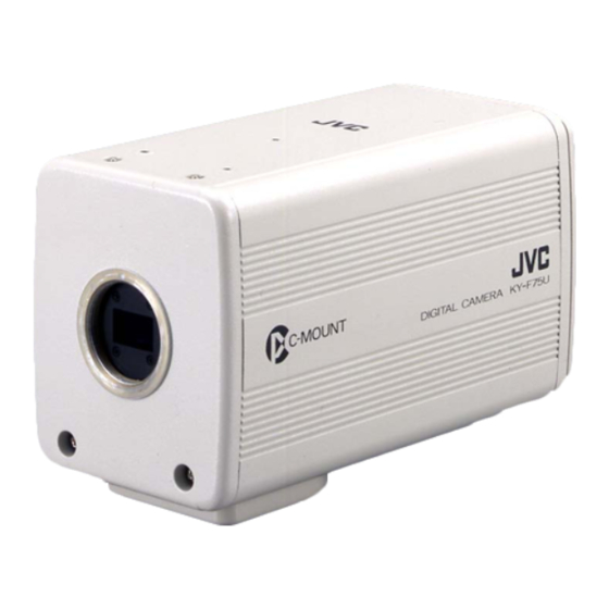
    5. Sonstiges (fortgesetzt) Technische Daten : 1/2-Zoll-IT-CCD × 3 Optischer Sensor Abtasttyp : Progressiv : 1,45 Millionen Pixel (1392 (H) × 1040 (V)) Verfügbare Pixel : 1280 × 960/1360 × 1024 Pixel RGB (umschaltbar) Effektive Pixelanzahl Seitenverhältnis : Etwa 4:3 Verschlusszeit : 4,010 sec bis 1/5906,836 sec Objektivfassung...
  • Seite 99 Außenabmessungen (Einheit: mm) 142.5 C-Mount C-MOUNT DIGITAL CAMERA KY-F75U 41.5 1/4-Zoll-Gewinde Änderungen von Entwurf und technischen Daten bleiben jederzeit vorbehalten.
  • Seite 100 Introduction Préparations Enregistrement 3CCD Caméra numérique Réglages KY-F75 MANUEL D’INSTRUCTIONS Divers...
  • Seite 101 Nous vous remercions d’avoir acheté la caméra Les explications techniques sont données: numérique JVC KY-F75. Anglais, pages E2 to E47 Allemand, pages G2 to G47 Français, pages F2 to F47 SAFETY PRECAUTIONS AVERTISSEMENT: POUR RÉDUIRE TOUT RISQUE DE FEU OU DE CHOC ÉLECTRIQUE, NE PAS EXPOSER...
  • Seite 102 F75 est conçu pour fonctionner dans des appareils qui ne sont pas destinés au patient. Les appareils KY-F75 et AA-P700EG ont été testés et sont conformes aux normes de sécurité IEC 601-1. L’utilisation d’accessoires non conformes aux exigences de sécurité correspondant à...
  • Seite 103 Sommaire 1. Introduction 4. Réglages Caractéristiques ........5 Ouverture et fermeture de l’écran de Accessoires et options ......5 réglage ............ 24 Consignes de sécurité pour un usage Ecran de réglage de l’exposition ..... 26 correct de l’appareil ........6 Ecran de réglage de la balance des Les commandes et leurs fonctions ....
  • Seite 104: Introduction

    1. Introduction Caractéristiques ● La KY-F75 est une caméra numérique utilisant trois capteurs CCD de 1/2” avec 1,45 million de pixels effectifs. ● Sortie de signal vidéo numérique de 1360 × 1024 pixels possible. ● Le DSP incorporé pour traitement en temps réel du signal vidéo envoyé sous forme de signal numérique RGB à...
  • Seite 105: Consignes De Sécurité Pour Un Usage Correct De L'appareil

    • Ne pas laisser l’appareil dans un endroit où il risque d’être exposé à un rayonnement ou aux rayons X, ni dans un endroit dégageant des gaz corrosifs. Nettoyage Pour nettoyer l’appareil, utiliser un chiffon de nettoyage sec ou un chiffon humecté d’une petite quantité d’alcool. Ne pas renverser de liquide dans la KY-F75.
  • Seite 106: Les Commandes Et Leurs Fonctions

    Les commandes et leurs fonctions [Face avant et fond] ³ ³ Monture d’objectif ¿ Orifices des vis de montage de la caméra (1/4") Bien que la monture d’objectif soit une monture de type C, il existe certaines res- Permettent de fixer la caméra à un dispositif trictions sur les objectifs que l’appareil peut de fixation ou à...
  • Seite 107: Configuration Des Broches Des Connecteurs

    1. Introduction (suite) Les commandes et leurs fonctions (suite) [Dos] Prise de commande à distance [RE- MOTE] (métallique à 10 broches, femelle) Permet de raccorder des périphériques, par exemple un déclencheur ou un flash. LENS Configuration des broches des connecteurs IEEE1394 page F9) REMOTE...
  • Seite 108 Prise de LENS (métallique à 12 broches, femelle) ATTENTION • Pour le raccordement de la télécommande, consulter son revendeur JVC. • Le câble de télécommande doit utiliser un câble blindé. La gaine extérieure du câble de télécommande doit être raccordée à...
  • Seite 109: Préparations

    Il est possible d’alimenter la KY-F75 via le connecteur IEEE 1394 de l’ordinateur. ATTENTION Si la KY-F75 est alimentée via le câble IEEE 1394, vérifier si la capacité du côté fournisseur d’alimentation est suffisante pour satisfaire la consommation de la KY-F75 (environ 600 mA dans le cas d’un courant CC de 12 V).
  • Seite 110 Si l’on utilise un objectif motorisé, il faudra utiliser l’adaptateur secteur AA-P700 vendu séparément pour alimenter la caméra. Raccorder le connecteur [DC IN] de la KY-F75 à l’AA-P700 avec le cordon d’alimentation CC. Fixer le filtre d’écrêtage fourni avec la KY-F75 au cordon d’alimentation CC.
  • Seite 111: Préparations De L'ordinateur

    2. Préparations (suite) Préparations de l’ordinateur L’image de la caméra s’affiche sur l’écran de l’ordinateur et la KY-F75 se pilote depuis l’ordinateur. Il n’est pas possible de raccorder tous les types d’ordinateur. Voir [Caractéristiques techniques des modèles de PC utilisables], page F45.
  • Seite 112: Procédure D'installation

    ROM fourni avec la KY-F75. Installer le logiciel d’application [KY-LINK] de la façon suivante. Insérer le CD-ROM fourni avec la KY-F75 dans le lecteur de CD-ROM de l’ordinateur. Sélectionner le dossier\ENU\Kylink sur le CD-ROM, et double-cliquer sur Setup.exe. Double-cliquer sur Setup.exe.
  • Seite 113: Raccordement À L'ordinateur

    Précautions relatives à l’alimentation • Si la KY-F75 est alimentée via le câble IEEE 1394, vérifier si la capacité du côté fournisseur d’alimentation est suffisante pour satisfaire la consommation de la KY-F75 (environ 600 mA dans le cas d’un courant CC de 12 V).
  • Seite 114: Montage Et Réglage De L'objectif

    Pour monter l’objectif, appuyer légèrement la section filetée de l’objectif sur la section filetée de la caméra, puis tourner lentement l’objectif ou la KY-F75 dans le sens des aiguilles d’une montre jusqu’à ce que l’objectif soit solidement vissé sur la caméra.
  • Seite 115: Raccordement De L'adaptateur Secteur

    Il est possible d’alimenter la KY-F75 par l’ordinateur via le câble IEEE 1394, mais avec un objectif motorisé, etc., il faudra utiliser le câble CC pour raccorder le connecteur [DC IN] de la KY-F75 au connecteur [TO CAMERA] de l’adaptateur secteur (AA-P700).
  • Seite 116 Mise sous tension Mettre l’AA-P700 sous tension, puis attendre 5 secondes ou plus avant de rappeler le logiciel d’application [KY-LINK]. Mise hors tension Refermer le logiciel d’application [KY-LINK], puis attendre 5 secondes ou plus avant de mettre l’AA-P700 hors tension. ATTENTION •...
  • Seite 117: Montage De La Caméra

    2. Préparations (suite) Montage de la caméra < Méthode de montage > Orifice de prévention de rotation Orifice de vis de montage de la caméra Support de montage de la caméra ● Pour le montage de la caméra, utiliser l’orifice de vis de montage de la caméra qui se trouve sur le support de montage de la caméra.
  • Seite 118: Prévention De Chute

    Prévention de chute Fil de prévention de chaîne métallique 6 mm Tête de caméra MEMO • Faire particulièrement attention lorsqu’on monte l’appareil sur un mur ou sur un plafond. Ne pas essayer de l’installer soi-même. Confier cette opération à une personne qualifiée.
  • Seite 119: Enregistrement

    Les images numériques sont transférées de la caméra à l’ordinateur à la vitesse de 7,5 images par seconde. Si l’on raccorde un interrupteur au pied ou un déclencheur externe à la KY-F75, il sera possible de geler les images de la caméra avec le signal d’entrée du déclencheur externe.
  • Seite 120: Lancement Du Logiciel D'application [Ky-Link]

    Lancement du logiciel d’application [KY-LINK] Mettre la KY-F75 sous tension, puis attendre 5 secondes ou plus avant de lancer le logiciel [KY-LINK]. Lancement de [KY-LINK] Sélectionner [Démarrer] [Programmes] [KY-LINK] [KY-LINK]. ● L’écran de lancement de KY-LINK apparaît. Ecran de lancement de KY-LINK Sélectionner Camera, puis cliquer sur le bouton [OK].
  • Seite 121: Gel De L'image

    ● Si l’on utilise une ou plusieurs des fonctions de diaphragme automatique, EEI et ALC. MEMO La fonction Gel de la KY-F75 s’effectue dans la mémoire de l’ordinateur en arrêtant la sortie de l’image de la caméra. En conséquence, si l’on envoie le déclencheur à la caméra alors que la fenêtre des images animées n’est pas affichée, aucune image n’apparaîtra, même si la fenêtre des images animées...
  • Seite 122: Capture D'images Fixes Sur L'ordinateur (Capture)

    Fermeture de l’application KY-LINK Sélectionner [Exit] dans le menu Fichier. ATTENTION • Après avoir fermé [KY-LINK], attendre 5 secondes ou plus avant de mettre la KY-F75 hors tension. • Ne pas mettre la caméra hors tension pendant que [KY-LINK] fonctionne.
  • Seite 123: Réglages

    [KY-LINK]. Les paramètres en vigueur au moment de la fermeture de [KY-LINK] sont automatiquement rappelés et validés sur la caméra au lancement suivant. Procédure Mettre la KY-F75 sous tension et attendre 5 secondes ou plus. Lancer le logiciel d’application [KY-LINK]. ( page F21.) Ouvrir l’écran de réglage.
  • Seite 124 Régler les rubriques de l’écran de réglage. Pour les paramètres des différents écrans, voir pages F26 à F42. Fin du réglage de l’écran de réglage Cliquer sur le bouton [X] (Fermeture). Bouton [X] (Fermeture). File [Load], [Save] ——— Enregistrement des paramètres dans l’ordinateur ——— ●...
  • Seite 125: Ecran De Réglage De L'exposition

    4. Réglages (suite) Ecran de réglage de l’exposition Cet écran permet de régler les paramètres relatifs au niveau d’image, comme le diaphragme, l’obturateur, et la sensibilité. Réglages de l’obturateur Bouton Restart Valide lorsque la vitesse d’obturation est de 2 secondes ou Réglages du moins en mode diaphragme...
  • Seite 126 [ ] indique les réglages usine. Rubrique Paramètre Contenu Iris mode [AUTO] Se règle en fonction de l’objectif utilisé. MANUAL AUTO : Avec un diaphragme automatique. MANUAL : • Avec un diaphragme manuel. • Objectif non monté • Pour utiliser le diaphragme manuel avec un objectif motorisé.
  • Seite 127 4. Réglages (suite) Exposure settings screen (continued) [ ] indique les réglages usine. Paramètre Rubrique Contenu Shutter [STEP] Permet de régler le mode de l’obturateur. V.SCAN STEP: La vitesse d’obturation se règle avec la rubrique [Speed]. V. SCAN: La vitesse d’obturation se règle avec la rubrique RANDOM [Speed].
  • Seite 128 [ ] indique les réglages usine. Rubrique Paramètre Contenu Gain [STEP] Permet de régler le mode de sensibilité. STEP: La sensibilité se règle avec la rubrique “Level”. V.GAIN ALC: La sensibilité se règle automatiquement en fonction de la luminosité ambiante. V.GAIN: La sensibilité...
  • Seite 129: Ecran De Réglage De La Balance Des Blancs

    4. Réglages (suite) Ecran de réglage de la balance des blancs Cet écran permet de régler les paramètres relatifs à la température de couleur au moment de la prise de vue, la balance des blancs et l’ombrage dynamique. Règle la température de couleur standard pour le réglage de la balance des blancs.
  • Seite 130 [ ] indique les réglages usine. Rubrique Paramètre Contenu Color 3200K Permet de régler la température de couleur standard de la ba- temp. 5600K lance des blancs. 3200K: Pour une utilisation avec une température de couleur faible, par exemple avec une lampe halogène, etc. 5600K: Pour une utilisation avec une température de couleur élevée, par exemple le soleil, etc.
  • Seite 131 4. Réglages (suite) Ecran de réglage de la balance des blancs (suite) [ ] indique les réglages usine. Rubrique Paramètre Contenu Shading [OFF] Permet de régler si l’appareil doit effectuer une correction d’ombrage dynamique. OFF: Pas de correction d’ombrage dynamique Correction d’ombrage dynamique Level (R) –...
  • Seite 132: Réglage Automatique De La Balance Des Blancs

    Régler la rubrique de la balance des blancs sur AUTO1 ou AUTO2. Cliquer sur le bouton Auto White. ● La KY-F75 règle automatiquement la balance des blancs. * Si l’on a sélectionné une vitesse d’obturation faible, le réglage de la balance des blancs peut prendre un certain temps.
  • Seite 133: Réglage De L'ombrage Dynamique

    4. Réglages (suite) Réglage de l’ombrage dynamique Il peut se produire un ombrage dynamique en fonction de la combinaison des objectifs et du système optique qui équipe les caméras à 3 capteurs CCD. Dans ce cas, effectuer le réglage décrit ci-dessous. Bouton Waveform window Ecran KY-LINK Barre d’outils...
  • Seite 134: Ecran De Réglage Du Processus

    Ecran de réglage du processus Cet écran permet de régler les paramètres relatifs à la qualité d’image, comme la compensation du détail, le gamma, et la compensation des taches blanches. Réglages du Réglage des détail taches lumineuses Réglages du Réglage ABL gamma Réglage du noir maître...
  • Seite 135 4. Réglages (suite) Ecran de réglage du processus (suite) Rubrique Paramètre Contenu Noise sup. Permet de réduire le bruit du signal vidéo. MIDDLE LOW/MIDDLE/HIGH : Le bruit est réduit. HIGH Le taux de réduction augmente dans l’ordre de LOW MIDDLE [OFF] HIGH.
  • Seite 136 [ ] indique les réglages usine. Rubrique Paramètre Contenu Master black – 99 Permet de régler le niveau de suppression (noir maître), qui est le noir standard lorsque l’objectif est recouvert de son bouchon. Pour mieux voir les détails dans les zones noires, augmenter le •...
  • Seite 137: Correction Des Taches Blanches

    4. Réglages (suite) Correction des taches blanches L’une des caractéristiques générales inhérentes aux capteurs CCD est qu’il risque d’apparaître des taches blanches sur l’image aux vitesses d’obturation lentes ou pendant une prise de vues à température élevée. Pour réduire ce phénomène, la caméra a été dotée d’une fonction de correction des taches blanches. Fonctionnement Détection des taches blanches Le nombre des taches et leur taille variant en fonction de la température, de la vitesse d’obturation,...
  • Seite 138: Ecran De Réglage De La Matrice De Couleur

    Ecran de réglage de la matrice de couleur Il permet de régler la teinte de couleur des images de la caméra. Sélectionne la matrice de couleur. Barre coulissante : Valide lorsque la matrice de couleur est réglée sur ON. Effectuer les réglages en déplaçant les barres coulissantes avec la souris.
  • Seite 139 4. Réglages (suite) Ecran de réglage de la matrice de couleur (suite) [ ] indique les réglages usine. Rubrique Paramètre Contenu Color matrix Permet de régler si les valeurs de la matrice couleur restent stan- [OFF] dard ou non. La matrice couleur peut être modifiée. Les réglages ci-dessous ne sont possibles qu’avec cette rubrique.
  • Seite 140: Ecran De Réglage De L'objectif

    Ecran de réglage de l’objectif Il permet de régler la méthode de commande du diaphragme en fonction de l’objectif utilisé. Sélectionne le mode de diaphragme. Réglage de niveau du diaphragme Valide lorsque le diaphragme est réglé en mode MANUAL. [ ] indique les réglages usine. Rubrique Paramètre Contenu...
  • Seite 141: Ecran De Réglage Du Système

    Il permet de régler la méthode d’annulation du gel d’image, et de sélectionner si une barre de couleur doit s’afficher ou non comme mire d’essai. Il permet également d’enregistrer les paramètres des écrans de réglage dans la mémoire de la KY-F75. Pour sélectionner la méthode d’annulation du gel d’image.
  • Seite 142: Divers

    5. Divers Synchronisation du flash et du déclencheur Pour synchroniser le flash sur l’entrée d’un déclencheur externe, utiliser le connecteur [RE- MOTE] du panneau arrière. Configuration des broches des connecteurs ( page F9) Si l’obturateur est réglé sur un mode autre que “RANDOM” “EEI” ( page F28, rubrique SHUTTER) ●...
  • Seite 143 5. Divers (suite) Synchronisation du flash et d’un déclencheur ex terne (suite) Si l’obturateur est réglé sur le mode RANDOM • L’accumulation du capteur CCD s’effectue en synchronisation avec l’entrée du déclencheur, et la sortie FLASH comme signal FLASH. • A la même vitesse d’obturation, le retard entre l’entrée FREEZE et la sortie FLASH est presque uniforme, comme indiqué...
  • Seite 144: A Propos Des Opérations Alc Et Eei

    A propos des opérations ALC et EEI ALC signifie “Automatic Level Control” (“commande de niveau automatique”) et EEI signifie “diaphragme électronique étendu”. ( Page F28) En effectuant les réglages respectifs, la commande de niveau automatique (ALC) fonctionnera en éclairage sombre, et l’obturateur électronique (EEI) fonctionnera en éclairage clair. De plus, le réglage du mode IRIS sur AUTO synchronise la sensibilité, le diaphragme et l’obturateur électronique de façon automatique et à...
  • Seite 145: Caractéristiques Techniques

    5. Divers (suite) Caractéristiques techniques Elément d’image : 3 capteurs CCD IT de 1/2" Type de balayage : Progressif : 1,45 million de pixels (1392 (H) × 1040 (V)) Pixels disponibles : 1280 × 960/1360 × 1024 pixels RGB (réglable) Nombre de pixels effectifs Rapport d’image : Environ 4:3...
  • Seite 146 Dimensions extérieures (unité: mm) 142.5 C-Mount C-MOUNT DIGITAL CAMERA KY-F75U 41.5 Vis de 1/4" La conception et les spécifications sont sujettes à modification sans préavis.
  • Seite 147 is a registered trademark owned by Victor Company Of Japan, Limited. is a registered trademark in Japan, the U.S.A., the U.K. and many other countries. Printed in Japan © 2004 Victor Company Of Japan, Limited LWT0059-001B...

Inhaltsverzeichnis