Wilo DrainLift WS 40 Einbau- Und Betriebsanleitung
Vorschau ausblenden
Andere Handbücher für DrainLift WS 40:
- Einbau- und betriebsanleitung (40 Seiten)
Inhaltsverzeichnis
Werbung
Verfügbare Sprachen
Verfügbare Sprachen
Quicklinks
Werbung
Kapitel
Inhaltsverzeichnis

Verwandte Anleitungen für Wilo DrainLift WS 40


Inhaltszusammenfassung für Wilo DrainLift WS 40
- Seite 1 Pioneering for You Wilo-DrainLift WS 40/50 de Einbau- und Betriebsanleitung Notice de montage et de mise en service en Installation and operating instructions Istruzioni di montaggio, uso e manutenzione · 6087339 • Ed.2020-07/05...
- Seite 2 Fig. 2.1: DrainLift WS 40E Ø570 Ø63 Ø75 R 1½ Ø50 Fig. 2.2: DrainLift WS 40D Ø570 Ø63 Ø75 Ø50 1000...
- Seite 3 Fig. 2.3: DrainLift WS 50E Ø570 Ø63 Ø75 Ø50 Fig. 2.4: DrainLift WS 50D Ø570 Ø63 Ø75 Ø50 1000...
- Seite 5 Deutsch ......................English ....................... Français ......................Italiano.......................
-
Seite 6: Inhaltsverzeichnis
8 Außerbetriebnahme/Ausbau .............................. 31 Personalqualifikation...................................... 31 Pflichten des Betreibers .................................... 31 Außerbetriebnahme ....................................... 31 Reinigen und desinfizieren .................................... 32 Ausbau der Pumpe...................................... 32 9 Instandhaltung .................................. 33 10 Ersatzteile.................................... 33 11 Störungen, Ursachen und Beseitigung .......................... 33 WILO SE 05... - Seite 7 12 Entsorgung .................................... 33 12.1 Schutzkleidung........................................ 33 Einbau- und Betriebsanleitung Wilo-DrainLift WS 40/50...
-
Seite 8: Allgemeines
Alle Angaben zum Produkt und Kennzeichnungen am Produkt beachten. Die Sprache der Originalbetriebsanleitung ist Deutsch. Alle weiteren Sprachen dieser Anleitung sind eine Übersetzung der Originalbetriebsanleitung. Urheberrecht Das Urheberrecht an dieser Anleitung verbleibt bei Wilo. Alle Inhalte jeglicher Art dürfen nicht: ƒ Vervielfältigt werden. -
Seite 9: Personalqualifikation
Person mit geeigneter fachlicher Ausbildung, Kenntnissen und Erfahrung, um die Gefahren von Elektrizität zu erkennen und zu vermeiden. ƒ Montage-/Demontagearbeiten: ausgebildete Fachkraft Anlagentechnik für Sanitär- anlagen Befestigung und Auftriebssicherung, Anschluss von Kunststoffrohren ƒ Erdeinbau (Unterflur): ausgebildete Fachkraft im Tief- und Rohrleitungsbau Einbau- und Betriebsanleitung Wilo-DrainLift WS 40/50... -
Seite 10: Elektrischer Anschluss
Arbeitsbereich kennzeichnen und absperren. ƒ Umherliegenden Gegenständen aus dem Arbeitsbereich entfernen. ƒ Unbefugte Personen aus dem Arbeitsbereich fernhalten. ƒ Wenn die Witterungsverhältnisse ein sicheres Arbeiten nicht mehr ermöglichen, Ar- beiten abbrechen. ƒ Nur technisch einwandfreie Hebezeuge verwenden. WILO SE 05... -
Seite 11: Während Des Betriebs
HINWEIS! Wenn fetthaltiges Abwasser gefördert wird, Fettabscheider vor dem Pum- penschacht installieren! Pumpenschacht • • WS 40E mit Rexa CUT GI... • • • WS 40E mit Rexa CUT GE... • • WS 40D mit Rexa CUT GI... Einbau- und Betriebsanleitung Wilo-DrainLift WS 40/50... -
Seite 12: Nichtbestimmungsgemäße Verwendung
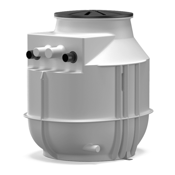
Schachtkörper mit Verrippungen für eine Hohe Formsteifigkeit und Auftriebssicherheit. Fig. 1: Aufbau Die Zuläufe sind frei wählbar. Zum Anschlagen der Hebemittel sind zwei Transportösen integriert. Der Schachtdeckel ist begehbar und mit max. 200 kg belastbar. Für die Ge- bäudeaufstellung ist der Pumpenschacht mit einer Bodenbefestigung ausgestattet. WILO SE 05... -
Seite 13: Technische Daten
Beispiel: DrainLift WS 40E DrainLift Produktfamilie Pumpenschacht Baugröße Schachtausführung: ƒ E = Einzelpumpenschacht ƒ D = Doppelpumpenschacht ƒ Lieferumfang Kunststoffschacht mit eingebauter Verrohrung – Verrohrung mit Absperrschieber und Überwasserkupplung mit integriertem Rück- flussverhinderer ƒ Schachtdeckel mit Dichtung Einbau- und Betriebsanleitung Wilo-DrainLift WS 40/50... -
Seite 14: Zulaufset Mit Lochsäge 124 Mm (5 In) Und Dichtung Dn
Sicherstellen, dass sich der Pumpenschacht beim Heben und Senken nicht verklemmt. Die max. zulässige Tragfähigkeit des Hebemittels nicht überschrei- ten! Hebemittel vor der Verwendung auf eine einwandfreie Funktion prüfen! Um Transportschäden zu vermeiden, die folgenden Punkte beachten: ƒ Pumpenschacht immer auf einer Palette transportieren. WILO SE 05... -
Seite 15: Lagerung
Schaltgerät laut den Angaben des Herstellers einlagern. Installation und elektrischer Anschluss ƒ Personalqualifikation Montage-/Demontagearbeiten: ausgebildete Fachkraft Anlagentechnik für Sanitär- anlagen Befestigung und Auftriebssicherung, Anschluss von Kunststoffrohren ƒ Erdeinbau (Unterflur): ausgebildete Fachkraft im Tief- und Rohrleitungsbau Einbau- und Betriebsanleitung Wilo-DrainLift WS 40/50... -
Seite 16: Aufstellungsarten
Personal die Betriebsordnung erhalten und gelesen hat! GEFAHR Lebensgefahr durch gefährliche Alleinarbeit! Arbeiten in Schächten und engen Räumen sowie Arbeiten mit Absturzgefahr sind gefährliche Arbeiten. Diese Arbeiten dürfen nicht in Alleinarbeit erfolgen! Es muss eine zweite Person zur Absicherung anwesend sein. WILO SE 05... - Seite 17 Kabelquerschnitt und die Kabellänge für die gewählte Verlegeart ausreichend sind. ƒ Installation von Schaltgeräten: Angaben der Herstelleranleitung beachten (IP-Klasse, überflutungssicher, Ex-Bereiche)! Erdeinbau VORSICHT Vorsicht vor hohen Grundwasserpegeln! Durch erhöhtes Grundwasser kann der Pumpenschacht auftreiben. Angaben zum maximal zulässigen Grundwasserstand beachten! Einbau- und Betriebsanleitung Wilo-DrainLift WS 40/50...
-
Seite 18: Aufstellung Des Pumpenschachts Außerhalb Von Gebäuden
Druckbeständigkeit der Verrohrung und der Rohrverbindungen ƒ Zugfestigkeit der Rohrverbindungen (= längskraftschlüssige Verbindung) ƒ Rohrleitungen spannungs- und schwingungsfrei anschließen. ƒ Im Zulauf und der Druckrohrleitung bauseits einen Absperrschieber vorsehen! 6.4.3 Arbeitsschritte Die Montage des Pumpenschachts erfolgt in den folgenden Schritten: WILO SE 05... -
Seite 19: Vorbereitende Arbeiten
Pumpe eine separate Verrohrung. Somit auch zwei – Schachtabdeckung Druckanschlüsse. – Hosenrohr – Schaltgerät Die Pumpenschächte WS 40...D und WS 50...D haben für – Niveausteuerung jede Pumpe eine separate Verrohrung. Somit auch zwei Druckanschlüsse. – Schachtverlängerung (für Höhenausgleich) – Schaltgerät – Niveausteuerung Einbau- und Betriebsanleitung Wilo-DrainLift WS 40/50... -
Seite 20: Pumpenschacht Aufstellen
Position der Zulauf-, Druck- und Entlüftungsleitung Fig. 5: Grube ausheben ƒ Schachtverlängerung (300 mm/12 in) für einen Höhenausgleich zum Oberflächenni- veau. ƒ Grundwasser Vorhandenes Grundwasser mit einer Grundwasserabsenkung abpumpen. ƒ Lokale Frosttiefe berücksichtigen. ‡ Vorbereitende Arbeiten abgeschlossen. ‡ Grubenabmessungen festgelegt. ‡ Bauseitige Rohrleitungen vorbereiten. WILO SE 05... -
Seite 21: Druckleitung Anschließen
1. Klemmverschraubung auf den Druckstutzen aufstecken. 2. Bauseitige Druckleitung in die Klemmverschraubung stecken. 3. Klemmverschraubung verschrauben. ▶ Druckleitung angeschlossen. Nächster Schritt: Zulauf anschließen. 6.4.7 Zulauf anschließen Der Zulauf kann freiwählbar in den gekennzeichnten Flächen an der Schachtwand erfol- gen. Einbau- und Betriebsanleitung Wilo-DrainLift WS 40/50... - Seite 22 1. Zulaufpunkt am Pumpenschacht markieren. 2. Mit der beigelegten Lochsäge das Loch für den Zulauf in die Schachtwand bohren. Bei Bohrungen am Pumpenschacht die folgenden Punkte beachten: - Maße der Zulaufflächen beachten. VORSICHT! Die Bohrung muss komplett in- WILO SE 05...
-
Seite 23: Be- Und Entlüftung Anschließen
1. Be- und Entlüftungsstutzen öffnen: Sägekante ca. 25 mm. 2. Sägekante entgraten und glätten. 3. HT-Überschiebmuffe auf geöffneten Be- und Entlüftungsstutzen stecken. 4. Bauseitiges Be- und Entlüftungsrohr in die HT-Überschiebmuffe stecken. ▶ Be- und Entlüftung installiert. Nächster Schritt: Notentleerung anschließen (nur Gebäudeaufstellung). Einbau- und Betriebsanleitung Wilo-DrainLift WS 40/50... -
Seite 24: Notentleerung Anschließen (Nur Gebäudeaufstellung)
Alternativ können die Anschlusskabel auch über die Entlüftungsleitung nach außen geführt werden. Folgende Punkte beim Anschluss des Kabelrohrs beachten: ƒ Vor dem Anschluss des Kabelrohrs das Einziehband einziehen. ƒ Alle Anschlüsse komplett dicht ausführen. WILO SE 05... - Seite 25 Pumpenschacht gegen Auftrieb sichern. Gegebenenfalls den Pumpenschacht mit Wasser befüllen. ƒ Die Angaben zum Füllmaterial sind Mindestanforderungen. Die lokalen Vorschriften prüfen und einhalten. ƒ Verfüllung und Verdichtung der Rohrleitungen laut den lokalen Vorschriften ausfüh- ren. Einbau- und Betriebsanleitung Wilo-DrainLift WS 40/50...
-
Seite 26: Pumpe Installieren
10.Hebekette vom Hebemittel lösen und am Kettenhaken im Pumpenschacht einhän- gen. ▶ Pumpe installiert. Nächster Schritt: Niveausteuerung installieren. 6.4.14 Niveausteuerung installieren Die Niveauerfassung kann auf die folgenden Arten erfolgen: ƒ Niveausensor ƒ Schwimmerschalter HINWEIS! Das Schaltgerät muss die richtigen Eingänge für die gewählten Signalge- ber haben! WILO SE 05... -
Seite 27: Niveausensor
Innerhalb des Pumpenschachts kann sich eine explosive Atmosphäre bilden. Wenn die Kabeldurchführung nicht luftdicht verschlossen wird, kann sich die explosive At- mosphäre in den Betriebsraum ausbreiten. Es besteht Lebensgefahr durch Explosion! Kabeldurchführung luftdicht ausführen. Einbau- und Betriebsanleitung Wilo-DrainLift WS 40/50... -
Seite 28: Schachtabdeckung Montieren
3. An der vorgesehenen Stelle in der Schachabdeckung eine 3 mm Bohrung anbrin- gen. Bohrung durch den Deckel und den Pumpenschacht bohren. 4. Beiliegende Schraube eindrehen. ▶ Schachtabdeckung montiert und gesichert. Elektrischen Anschluss ausführen. WILO SE 05... -
Seite 29: Elektrischer Anschluss
Sicherstellen, dass das gesamte Personal die Einbau- und Betriebsanleitungen gele- sen und verstanden hat. ƒ Alle bauseitigen Sicherheitseinrichtungen sind eingeschaltet und funktionieren ein- wandfrei. ƒ Der Pumpenschacht und die verbaute Pumpe sind für den Einsatz in den vorgegebe- nen Betriebsbedingungen geeignet. Einbau- und Betriebsanleitung Wilo-DrainLift WS 40/50... -
Seite 30: Bedienung
Standardmäßig läuft die Pumpstation im Automatikbetrieb und wird über die integrierte Niveausteuerung ein- und ausgeschaltet. ‡ Inbetriebnahme wurde durchgeführt. ‡ Testlauf wurde erfolgreich durchgeführt. ‡ Bedienung und Funktionsweise der Pumpstation sind bekannt. ‡ Druckleitung komplett mit Wasser gefüllt. WILO SE 05... -
Seite 31: Während Des Betriebs
- Schaltgerät am Hauptschalter ausschalten. ▶ Die Pumpstation ist außer Betrieb genommen. Wenn die Pumpstation für eine längere Zeit außer Betrieb genommen wird, in regelmä- ßigen Abständen (vierteljährlich) einen Funktionslauf durchführen. VORSICHT! Funkti- onslauf wie unter „Testlauf“ beschrieben durchführen. Einbau- und Betriebsanleitung Wilo-DrainLift WS 40/50... -
Seite 32: Reinigen Und Desinfizieren
• Angaben der Betriebsordnung beachten! Der Betreiber muss sicherstellen, dass das Personal die Betriebsordnung erhalten und gelesen hat! GEFAHR Lebensgefahr durch elektrischen Strom! Unsachgemäßes Verhalten bei elektrischen Arbeiten führt zum Tod durch Strom- schlag! Elektrische Arbeiten muss eine Elektrofachkraft nach den lokalen Vorschrif- ten ausführen. WILO SE 05... -
Seite 33: Instandhaltung
Serien- oder Artikelnummer angegeben wer- den. Technische Änderungen vorbehalten! Störungen, Ursachen und Be- Wenn Störungen auftreten, die Betriebsanleitungen der einzelnen Komponenten be- seitigung achten. Entsorgung 12.1 Schutzkleidung Getragene Schutzkleidung muss nach den lokal gültigen Richtlinien entsorgt werden. Einbau- und Betriebsanleitung Wilo-DrainLift WS 40/50... - Seite 34 During operation ...................................... 58 8 Shut-down/dismantling................................. 58 Personnel qualifications.................................... 58 Operator responsibilities.................................... 58 Shut-down........................................ 59 Clean and disinfect ...................................... 59 Pump removal........................................ 60 9 Maintenance and repair................................ 60 10 Spare parts.................................... 61 11 Faults, causes and remedies .............................. 61 WILO SE 05...
- Seite 35 12 Disposal.................................... 61 12.1 Protective clothing ...................................... 61 Installation and operating instructions Wilo-DrainLift WS 40/50...
-
Seite 36: General Information
Distribute any content. ƒ Use any content for competition purposes without authorisation. Wilo shall reserve the right to change the listed data without notice and shall not be li- able for technical inaccuracies and/or omissions. Subject to change Wilo shall reserve the rights to make technical changes to the product and individual components. -
Seite 37: Personnel Qualifications
Person with appropriate technical training, knowledge and experience who can identify and prevent electrical hazards. ƒ Installation/dismantling work: trained specialist in plant technology for sanitary fa- cilities Fixation and buoyancy safeguards, connection of plastic pipes Installation and operating instructions Wilo-DrainLift WS 40/50... -
Seite 38: Electrical Connection
Demarcate and cordon off the working area. ƒ Remove objects lying around from the work area. ƒ Keep unauthorised persons away from the working area. ƒ If the weather conditions mean it is no longer possible to work safely, stop work. WILO SE 05... -
Seite 39: During Operation
NOTICE! Install grease traps upstream of the pump chamber if pumping greasy sewage! Pump chamber • • WS 40E with Rexa CUT GI... • • • WS 40E with Rexa CUT GE... • • WS 40D with Rexa CUT GI... Installation and operating instructions Wilo-DrainLift WS 40/50... -
Seite 40: Improper Use
Two lifting eyes are integrated for attaching the lifting equipment. The chamber cover can be walked on and can be loaded with max. 200 kg. For the building installation, the pump chamber is equipped with a floor fixation. WILO SE 05... -
Seite 41: Technical Data
Pipework with gate valve and surface coupling with integrated non-return valve ƒ Chamber cover with gasket ƒ HT double socket 50 mm (2 in) for evacuation connection ƒ Inlet set with hole saw 124 mm (5 in)and gasket DN 100 Installation and operating instructions Wilo-DrainLift WS 40/50... -
Seite 42: Accessories
Secure the pump chamber against slipping. When lashing, make sure that the plastic parts do not deform. ƒ Close any openings, ensuring they are sealed watertight. ƒ Remove loose accessories from the pump chamber and pack them separately. WILO SE 05... -
Seite 43: Storage
Ground installation (underground): trained specialist in underground and pipeline construction Excavate and prepare the pit, backfill the pit, buoyancy safeguards, connection of plastic pipes. ƒ Lifting work: trained specialist for the operation of lifting devices Lifting equipment, lifting gear, attachment points Installation and operating instructions Wilo-DrainLift WS 40/50... -
Seite 44: Installation Types
Hand and foot injuries due to lack of protective equipment! Danger of (serious) injuries during work. Wear the following protective equipment: • Safety gloves for protection against cuts • Safety shoes • Safety helmet must be worn if lifting equipment are used! WILO SE 05... - Seite 45 NOTICE Installation of the pump chamber outside buildings Observe EN 1610 and local regulations during ground installation! ƒ Prepare the installation site: – Clean, free of coarse solids Installation and operating instructions Wilo-DrainLift WS 40/50...
-
Seite 46: Work Steps
Install the level control device. Backfill the pit. ƒ ƒ Lay the connection cable. Install the pump. ƒ ƒ Fit the chamber cover. Install the level control device. ƒ Lay the connection cable. ƒ Fit the chamber cover. WILO SE 05... -
Seite 47: Preparatory Tasks
7. Align the pump chamber with the boreholes. 8. Attach the pump chamber to the floor (floor fixation). ▶ Pump chamber installed so as to protect against buoyancy and twisting. Next step: Connect the pressure pipe. Installation and operating instructions Wilo-DrainLift WS 40/50... -
Seite 48: Connecting The Pressure Pipe
- Chamber cover flat to surface level ▶ Pump chamber installed. Next step: Connect the pressure pipe. 6.4.6 Connecting the pressure pipe DrainLift WS 40E/50E DrainLift WS 40D/50D Fig. 6: Pressure connection Pressure connection Observe the following information when connecting the pressure pipe: WILO SE 05... - Seite 49 ƒ Lay the inlet pipe with a slope to the pump chamber so that it can drain automatical- ƒ All connections must be completely tight! ƒ Install gate valve in the inlet! Installation and operating instructions Wilo-DrainLift WS 40/50...
- Seite 50 The connection of an aeration and venting line is a specified requirement. Observe the following points when connecting the aeration and venting line: ƒ For building installation: Guide the aeration and venting line over the roof. ƒ All connections must be completely tight. WILO SE 05...
- Seite 51 Shut off the inlet and drain the pump chamber. DrainLift WS 40E/50E DrainLift WS 40D/50D Fig. 10: Emergency drain connection Emergency drain connection Observe the following points when installing a diaphragm hand pump: Installation and operating instructions Wilo-DrainLift WS 40/50...
- Seite 52 2. Screw the pump chamber extension onto the pump chamber. 3. Lock the pump chamber extension with the enclosed screw. Fig. 12: Fit the pump chamber extension - Make a 3 mm drilled hole approximately 50 mm (2 in) from the top of the pump WILO SE 05...
-
Seite 53: Install The Pump
CAUTION! If the pump and discharge pipe are drained, do not bump into and get stuck on the chamber fittings. Depending on the pump type, turn the pump 90° when draining. 9. Couple the discharge pipe into the surface coupling. Installation and operating instructions Wilo-DrainLift WS 40/50... -
Seite 54: Level Sensor
* The values refer to an inlet floor of 450 mm. The value can be adjusted if the inlet is higher. NOTICE! For increased operational reliability, install a separate float switch for high water detection! Fig. 16: Level sensor installation WILO SE 05... - Seite 55 There is a risk of fatal injury due to explosion! Insert the gasket correctly into the chamber cover. ƒ The chamber cover can be secured against unauthorised opening. ƒ The chamber cover can be walked on. ƒ The maximum load of the chamber cover is 200 kg (441 lb). Installation and operating instructions Wilo-DrainLift WS 40/50...
-
Seite 56: Electrical Connection
Foot injuries due to a lack of protective equipment! Danger of (serious) injuries during work. Wear safety shoes! CAUTION Damage in the pump chamber! Coarse contaminants can cause damage to the pump chamber. Remove coarse con- taminants from the pump chamber before commissioning. WILO SE 05... -
Seite 57: Personnel Qualifications
NOTICE! Malfunction! Do not hold water jet directly above the float switch! 6. Pump is switched on and off using the level control. ⇒ Carry out at least two complete pumping procedures of all pumps when con- ducting a test run. Installation and operating instructions Wilo-DrainLift WS 40/50... -
Seite 58: Operation
Take immediate countermeasures if there is a build-up of toxic or suffocating gases! ƒ When working in enclosed spaces, a second person must be present for safety reas- ons. ƒ When using lifting equipment, observe all regulations for working with and under suspended loads! WILO SE 05... -
Seite 59: Shut-Down
8. Pump out the remaining pumped fluid via emergency draining. 9. Decommission the pumping station. 10.Allow the pumping station to dry out. 11.Fit the chamber cover. ▶ Pumping station disinfected. The individual components can now be removed. Installation and operating instructions Wilo-DrainLift WS 40/50... -
Seite 60: Pump Removal
Check the pumps are working correctly each time they are removed. Pump ƒ Carry out maintenance work according to the manufacturer's instructions in the in- stallation and operating instructions. Switchgear ƒ Carry out maintenance work according to the manufacturer's instructions in the in- stallation and operating instructions. WILO SE 05... -
Seite 61: Spare Parts
Faults, causes and remedies If faults occur, observe the installation and operating instructions of the individual components. Disposal 12.1 Protective clothing Used protective clothing must be disposed off in accordance with the locally applicable guidelines. Installation and operating instructions Wilo-DrainLift WS 40/50... - Seite 62 Qualification du personnel..................................... 88 Obligations de l'opérateur ..................................... 88 Mise hors service ...................................... 88 Nettoyer et désinfecter.................................... 88 Démontage de la pompe.................................... 89 9 Maintenance .................................... 90 10 Pièces de rechange ................................. 90 11 Pannes, causes et remèdes .............................. 90 WILO SE 05...
- Seite 63 12 Élimination.................................... 90 12.1 Vêtements de protection.................................... 90 Notice de montage et de mise en service Wilo-DrainLift WS 40/50...
-
Seite 64: Généralités
Interdiction de diffusion. ƒ Interdiction d'exploitation à des fins de concurrence. Wilo se réserve le droit de modifier sans préavis les données susnommées et décline toute responsabilité quant aux inexactitudes et/ou oublis techniques éventuels. Réserve de modifications Wilo se réserve le droit d'effectuer des modifications techniques sur le produit ou sur ses différents composants. -
Seite 65: Qualification Du Personnel
⇒ Remarque/instructions ▶ Résultat ƒ Qualification du personnel Travaux électriques : électricien formé Une personne bénéficiant d'une formation, de connaissances et d'expérience pour identifier les dangers de l'électricité et les éviter. Notice de montage et de mise en service Wilo-DrainLift WS 40/50... -
Seite 66: Raccordement Électrique
ƒ La présence de personnes sous les charges suspendues est interdite. Ne pas déplacer les charges au-dessus des zones de travail occupées. ƒ Travaux de montage/démontage Porter l'équipement de protection suivant : – Chaussures de protection WILO SE 05... -
Seite 67: Pendant Le Fonctionnement
Comme cuve en dehors des bâtiments (installation enterrée). AVIS ! Si les eaux chargées qui sont pompées contiennent des matières grasses, ins- taller un séparateur de graisse en amont de la cuve. Notice de montage et de mise en service Wilo-DrainLift WS 40/50... -
Seite 68: Utilisation Non Conforme À L'usage Prévu
Produits de nettoyage, de désinfection, de rinçage et de lavage en quantités surdo- sées et provoquant une formation de mousse disproportionnée ƒ Eau potable Le respect de cette notice fait aussi partie de l'utilisation conforme. Toute utilisation sortant de ce cadre est considérée comme non conforme. WILO SE 05... -
Seite 69: Description Du Produit
La pompe s'arrête dès que le niveau de désactivation est atteint. Notice de montage et de mise en service Wilo-DrainLift WS 40/50... -
Seite 70: Désignation
Personne ne doit se trouver sous des charges en suspension ! Cela comporte un risque de blessures (graves) à cause de possibles chutes de composants. La charge ne doit pas être soulevée au-dessus de postes de travail sur lesquels se trouvent des personnes ! WILO SE 05... -
Seite 71: Stockage
Respecter les points suivants lors du stockage : ƒ Vidanger entièrement la cuve. ƒ Disposer la cuve sur une surface ferme. Vérifier la stabilité. ƒ Protéger la cuve contre les chutes et les glissements ! Notice de montage et de mise en service Wilo-DrainLift WS 40/50... -
Seite 72: Montage Et Raccordement Électrique
ƒ Vérifier que les plans d'installation disponibles (plans de montage, lieu d'installation, conditions d'alimentation) sont complets et corrects. ƒ Poser et préparer les tuyauteries conformément au plan d'installation. WILO SE 05... -
Seite 73: Montage
état technique. S'assurer que la cuve ne se bloque pas lors du levage et de la descente. Ne pas dépasser la charge admissible maximale pour l'instrument de le- vage ! Vérifier le fonctionnement sans aucune anomalie de l'instrument de levage avant l'utilisation ! Notice de montage et de mise en service Wilo-DrainLift WS 40/50... - Seite 74 Ne pas stationner dans la zone de pivotement de l'appareil de levage. ƒ Prévoir un tire-fil pour l'installation des câbles de raccordement. ƒ Montage de coffrets de commande : Respecter les indications du fabricant (classe IP, protection contre la submersion, secteurs à risque d'explosion). WILO SE 05...
- Seite 75 Poser le câble de raccordement. Installer la pompe. ƒ ƒ Monter le couvercle de cuve. Installer le pilotage du niveau. ƒ Poser le câble de raccordement. ƒ Monter le couvercle de cuve. Notice de montage et de mise en service Wilo-DrainLift WS 40/50...
-
Seite 76: Travaux Préparatoires
7. Aligner la cuve sur les perçages. 8. Fixer la cuve au sol (fixation au sol). ▶ La cuve est montée de manière à être protégée contre les poussées et les distor- sions. Étape suivante : Raccorder la conduite de refoulement. WILO SE 05... -
Seite 77: Raccordement De La Conduite De Refoulement
- Couvercle de cuve plan par rapport à la surface du sol ▶ Cuve installée. Étape suivante : Raccorder la conduite de refoulement. 6.4.6 Raccordement de la conduite de DrainLift WS 40E/50E DrainLift WS 40D/50D refoulement Fig. 6: Raccord côté refoulement Notice de montage et de mise en service Wilo-DrainLift WS 40/50... - Seite 78 Pour que la conduite d'arrivée puisse fonctionner à vide de manière autonome, dis- poser la conduite d'arrivée en pente vers la cuve. ƒ Effectuer les raccordements de façon à les rendre totalement étanches. ƒ Installer une vanne d'arrêt dans l'arrivée. WILO SE 05...
- Seite 79 ƒ Pour installation en bâtiment : Faire passer l'évent et la conduite de purge par le toit. ƒ Effectuer les raccordements de façon à les rendre totalement étanches. Notice de montage et de mise en service Wilo-DrainLift WS 40/50...
- Seite 80 ATTENTION ! Si les pompes tombent en panne, le fluide reflue dans l'arrivée et peut faire éclater la cuve. Bloquer l'arrivée et vidanger la cuve. DrainLift WS 40E/50E DrainLift WS 40D/50D Fig. 10: Raccordement de la vidange d'urgence WILO SE 05...
- Seite 81 ▶ Fourreau à câble installé. Étape suivante : installation de l'extension de cuve (si né- cessaire). 6.4.11 Montage de l'extension de cuve L'extension de cuve permet de compenser la hauteur de 300 mm (12 in). Notice de montage et de mise en service Wilo-DrainLift WS 40/50...
- Seite 82 2. À l'aide d'une couche de remblai, égaliser le niveau en surface par rapport au cou- vercle de cuve. AVIS ! Si la nature du sol environnant est non cohésive, le remblai peut être constitué de ce même matériau. Grosseur de grain max. : 20 mm ! ▶ Fosse remblayée. Étape suivante : installer la pompe. WILO SE 05...
- Seite 83 Afin d'éviter un risque de reflux dans la conduite d'arrivée, régler le déclenchement de l'alarme trop plein à la hauteur du fil d'eau arrivée. Notice de montage et de mise en service Wilo-DrainLift WS 40/50...
-
Seite 84: Capteur De Niveau
AVIS ! Pour pouvoir soulever la pompe de la cuve (pour l'entretien par exemple), prévoir une longueur suffisante des câbles de raccordement. ƒ Poser les câbles de raccordement jusqu'au coffret de commande ou à la prise de courant conformément aux dispositions locales applicables. WILO SE 05... -
Seite 85: Raccordement Électrique
Effectuer le raccordement électrique des différents composants selon les notices de montage et de mise en service respectives. ƒ Installer l'alimentation réseau et les coffrets de commande de manière à les protéger contre la submersion. Notice de montage et de mise en service Wilo-DrainLift WS 40/50... -
Seite 86: Mise En Service
La commande de l'installation s'effectue au moyen du coffret de commande. Pour plus d'informations sur la commande du coffret de commande et sur les différentes indica- tions, consulter la notice de montage et de mise en service du coffret de commande. WILO SE 05... -
Seite 87: Fonctionnement « Test
échangée est insuf- fisante : – Prévoir des mesures d'isolation au-dessus du couvercle de la cuve. Notice de montage et de mise en service Wilo-DrainLift WS 40/50... -
Seite 88: Mise Hors Service/Démontage
• Gants de protection ⇒ L'équipement de protection mentionné constitue une exigence minimale, respecter les indications du règlement intérieur. L'opérateur doit s'assurer que le personnel a reçu et pris connaissance du règlement intérieur ! ‡ Station de relevage mise hors service. WILO SE 05... -
Seite 89: Démontage De La Pompe
La pompe peut être retirée de la cuve pour effectuer les travaux d'entretien. ‡ Station de relevage mise hors service. ‡ Station de relevage et ensemble des composants désinfectés. ‡ Équipement de protection revêtu. ‡ Zone de travail délimitée. Notice de montage et de mise en service Wilo-DrainLift WS 40/50... -
Seite 90: Maintenance
En cas de pannes, consulter les indications des notices de montage et de mise en ser- vice des différents composants. Élimination 12.1 Vêtements de protection Les vêtements de protection ayant été portés doivent être éliminés conformément aux directives en vigueur au niveau local. WILO SE 05... - Seite 91 Qualifica del personale .................................... 116 Doveri dell’utente ...................................... 116 Messa fuori servizio ...................................... 116 Pulire e disinfettare....................................... 117 Smontaggio della pompa ..................................... 117 9 Manutenzione.................................. 118 10 Parti di ricambio .................................. 118 11 Guasti, cause e rimedi ................................ 118 Istruzioni di montaggio, uso e manutenzione Wilo-DrainLift WS 40/50...
- Seite 92 12 Smaltimento .................................. 118 12.1 Indumenti protettivi ..................................... 119 WILO SE 05...
-
Seite 93: Generalità
Riserva di modifiche Wilo si riserva tutti i diritti di modifiche tecniche al prodotto o ai singoli componenti. Le illustrazioni impiegate possono variare dall’originale e fungono da rappresentazione esemplificativa del prodotto. - Seite 94 Dispositivo di protezione personale: indossare i guanti Dispositivo di protezione personale: indossare gli occhiali Dispositivo di protezione personale: indossare la mascherina Trasporto con due persone Nota utile Descrizioni testuali ‡ Requisito 1. Fase di lavoro/Elenco ⇒ Avviso/Istruzione WILO SE 05...
-
Seite 95: Qualifica Del Personale
Fissare il meccanismo di fissaggio sempre ai punti di aggancio. ƒ Controllare che il meccanismo di fissaggio sia saldo in posizione. ƒ Garantire la stabilità del dispositivo di sollevamento. ƒ Fare attenzione al campo di oscillazione. Istruzioni di montaggio, uso e manutenzione Wilo-DrainLift WS 40/50... -
Seite 96: Lavori Di Montaggio/Smontaggio
In caso di acque cariche che non possono essere immesse nella rete fognaria tramite pendenza naturale. ƒ Per il drenaggio antiriflusso nelle situazioni in cui i punti di scarico si trovano al di sotto del livello di riflusso. WILO SE 05... -
Seite 97: Impiego Non Rientrante Nel Campo D'applicazione
Detergenti, disinfettanti, detersivi per lavastoviglie e lavatrici in quantità eccessiva e altamente schiumogeni ƒ Acqua potabile Per un impiego conforme allo scopo previsto è necessario rispettare anche le presenti istruzioni per l’uso. Qualsiasi altro utilizzo è da considerarsi improprio. Istruzioni di montaggio, uso e manutenzione Wilo-DrainLift WS 40/50... -
Seite 98: Descrizione Del Prodotto
Se il livello dell’acqua sale fino al livello di inserimento, si accende la pompa. Le acque cariche accumulate vengono trasportate nel tubo di mandata a cura del com- mittente attraverso la conduttura di mandata. Quando viene raggiunto il livello di disin- serimento, la pompa si spegne. WILO SE 05... -
Seite 99: Chiave Di Lettura
Stazionamento sotto carichi sospesi! Sotto i carichi sospesi non devono sostare persone! La caduta di pezzi può causare (gravi) lesioni. Il carico non deve passare sopra postazioni di lavoro con persone pre- senti! Istruzioni di montaggio, uso e manutenzione Wilo-DrainLift WS 40/50... -
Seite 100: Stoccaggio
ƒ Posizionare il pozzetto su una base stabile. Verificare la stabilità. ƒ Assicurare il pozzetto contro il rovesciamento e lo scivolamento! ƒ Temperatura di stoccaggio max.: -15… 60 °C (5… 140 °F). Umidità relativa dell’aria max.: 90 %, non condensante. WILO SE 05... -
Seite 101: Installazione E Collegamenti Elettrici
Controllare che la documentazione di progetto disponibile (schemi di montaggio, luogo di installazione, condizioni di alimentazione) sia completa e corretta. ƒ Posare e predisporre le tubazioni secondo le indicazioni contenute nella documenta- zione di progetto. Istruzioni di montaggio, uso e manutenzione Wilo-DrainLift WS 40/50... -
Seite 102: Installazione
Installazione all’interno di un edificio AVVISO Installazione del pozzetto all’interno degli edifici Durante l’installazione rispettare la norma EN 12056 e le prescrizioni locali! ƒ Preparare il luogo di installazione: – Pulito, privo di impurità grossolane – Asciutto WILO SE 05... - Seite 103 Indicazioni sui collettori I collettori sono esposti a diverse pressioni durante l’esercizio. Si possono quindi verifi- care picchi di pressione (ad es. alla chiusura della valvola di ritegno) che possono com- Istruzioni di montaggio, uso e manutenzione Wilo-DrainLift WS 40/50...
- Seite 104 I pozzetti WS 40…D e WS 50…D hanno collettori separati – Controllo del livello per ciascuna pompa e quindi anche due raccordi di manda- – Prolunga del pozzo (per compensazione altezza) – Apparecchio di comando – Controllo del livello WILO SE 05...
- Seite 105 Prosciugare l’acqua di falda presente con un abbassamento dell’acqua di falda. ƒ Fare attenzione alla locale profondità di gelata. ‡ I lavori preparatori sono terminati. ‡ Dimensioni dello scavo stabilite. ‡ Preparazione delle tubazioni a cura del committente. Istruzioni di montaggio, uso e manutenzione Wilo-DrainLift WS 40/50...
-
Seite 106: Collegare L'alimentazione
2. Inserire il tubo di mandata a cura del committente nel pressacavo. 3. Avvitare il pressacavo. ▶ Tubo di mandata collegato. Passaggio successivo: Collegare l’alimentazione. 6.4.7 Collegare l’alimentazione L’alimentazione può essere collegata a scelta sulle superfici contrassegnate della parete del pozzetto. WILO SE 05... - Seite 107 1 fascetta serratubo 1. Segnare il punto di alimentazione sul pozzetto. 2. Con la sega circolare per fori fornita in dotazione praticare il foro per l’alimentazio- ne nella parete del pozzetto. Istruzioni di montaggio, uso e manutenzione Wilo-DrainLift WS 40/50...
- Seite 108 4. Inserire il tubo di ventilazione e sfiato a cura del committente nel manicotto senza battente HT. ▶ Sistema di aerazione e disaerazione installato. Passaggio successivo: Allacciare lo scarico di emergenza (solo per installazione all’interno di un edificio). WILO SE 05...
- Seite 109 Per l’allacciamento del tubo per cavo osserva- re i punti seguenti: ƒ Prima di allacciare il tubo per cavo applicare la sonda passacavi. ƒ Eseguire tutti i collegamenti completamente a tenuta. Istruzioni di montaggio, uso e manutenzione Wilo-DrainLift WS 40/50...
- Seite 110 Assicurare il pozzetto contro le spinte verticali. Eventualmente riempire il pozzetto con acqua. ƒ I dati del materiale di riempimento sono requisiti minimi. Verificare e rispettare le prescrizioni locali. ƒ Eseguire il riempimento e compattamento delle tubazioni secondo le normative lo- cali. WILO SE 05...
- Seite 111 ▶ Pompa installata. Passaggio successivo: Installare il controllo del livello. 6.4.14 Installare il controllo del livello Il rilevamento del livello può avvenire nei seguenti modi: ƒ Sensore di livello ƒ Interruttore a galleggiante Istruzioni di montaggio, uso e manutenzione Wilo-DrainLift WS 40/50...
- Seite 112 All'interno del pozzetto può formarsi un'atmosfera esplosiva. Se il passacavi non è a tenuta stagna, l'atmosfera esplosiva può diffondersi nel vano d’esercizio. Pericolo di morte per esplosione! Fare in modo che il passacavi sia ermetico. WILO SE 05...
- Seite 113 Possono fuoriuscire gas e fluido. 3. Nel punto previsto della copertura del pozzetto eseguire un foro di 3 mm. Eseguire il foro attraverso il coperchio e il pozzetto. 4. Serrare la vite in dotazione. Istruzioni di montaggio, uso e manutenzione Wilo-DrainLift WS 40/50...
-
Seite 114: Collegamenti Elettrici
Verificare che tutto il personale abbia letto e compreso le istruzioni di montaggio, uso e manutenzione. ƒ Tutti i dispositivi di sicurezza a cura del committente sono inseriti e funzionano cor- rettamente. ƒ Il pozzetto e la pompa installata sono adatti all’impiego nelle condizioni di esercizio indicate. WILO SE 05... -
Seite 115: Impiego
Funzionamento Di regola, la stazione di pompaggio opera in funzionamento automatico e viene accesa e spenta mediante il controllo del livello integrato. ‡ È stata eseguita la messa in servizio. Istruzioni di montaggio, uso e manutenzione Wilo-DrainLift WS 40/50... -
Seite 116: Durante Il Funzionamento
5. Prosciugare il restante fluido servendosi dello scarico di emergenza. 6. Spegnere il stazione di pompaggio: ATTENZIONE! Impedirne la riaccensione non autorizzata! - Staccare la spina dalla presa - Spegnere l’apparecchio di comando mediante l’interruttore principale. ▶ La stazione di pompaggio è stata messa fuori servizio. WILO SE 05... -
Seite 117: Pulire E Disinfettare
⇒ mascherina ⇒ guanti protettivi • Recuperare immediatamente le quantità gocciolate. • Rispettare le indicazioni dell’ordine di lavoro! L’utente deve verificare che il per- sonale abbia ricevuto e letto l’ordine di servizio! Istruzioni di montaggio, uso e manutenzione Wilo-DrainLift WS 40/50... -
Seite 118: Manutenzione
Al fine di evitare richieste di chiarimenti o ordini errati, indicare sempre il numero di serie o codice articolo. Con riserva di modifiche tecniche. Guasti, cause e rimedi Se si verificano guasti, rispettare le istruzioni di montaggio, uso e manutenzione dei sin- goli componenti. WILO SE 05... - Seite 119 Smaltimento Smaltimento 12.1 Indumenti protettivi Gli indumenti protettivi indossati devono essere smaltiti secondo le normative locali. Istruzioni di montaggio, uso e manutenzione Wilo-DrainLift WS 40/50...
- Seite 123 WILO Pompa Sistemleri Jakarta Timur, 13950 Sistemas Hidraulicos Lda. San. ve Tic. A.S¸ T +62 21 7247676 4475-330 Maia 34956 İstanbul citrawilo@cbn.net.id T +351 22 2080350 T +90 216 2509400 bombas@wilo.pt wilo@wilo.com.tr Further subsidiaries, representation and sales offices on www.wilo.com Oktober 2018...
- Seite 124 WILO SE Nortkirchenstr. 100 44263 Dortmund Germany T +49 (0)231 4102-0 T +49 (0)231 4102-7363 wilo@wilo.com Pioneering for You www.wilo.com...