Herunterladen Inhalt Inhalt Diese Seite drucken
Kübler CODIX 564 Handbuch

Kübler CODIX 564 Handbuch

Prozess-steuergeräte für temperatursensoren
Vorschau ausblenden Andere Handbücher für CODIX 564:
Inhaltsverzeichnis

Werbung

Verfügbare Sprachen
  • DE

Verfügbare Sprachen

  • DEUTSCH, seite 1
CODIX 564
für Thermoelemente J, K, N, R, S, T, E, B
Für
Sensoren im mV-Bereich
Für
Widerstandstemperaturfühler PT100
Für
Widerstandssensoren bis 500
Prozess-Steuergeräte
für Temperatursensoren
Process Controllers
for Temperature Sensors
Contrôleurs de process
pour sondes de température
Controllori di processo
per sonde di temperatura
Controlador de proceso
para sondas de temperatura

Werbung

Inhaltsverzeichnis
loading

Inhaltszusammenfassung für Kübler CODIX 564

  • Seite 1 CODIX 564 Prozess-Steuergeräte für Temperatursensoren Process Controllers for Temperature Sensors Contrôleurs de process für Thermoelemente J, K, N, R, S, T, E, B pour sondes de température Für Sensoren im mV-Bereich Für Widerstandstemperaturfühler PT100 Für Widerstandssensoren bis 500 Controllori di processo...
  • Seite 2: Inhaltsverzeichnis

    Inhaltsverzeichnis Vorwort Sicherheits- und Warnhinweise Bestimmungsgemäßer Gebrauch Schalttafeleinbau Elektrische Installation Beschreibung Anzeige/Bedienelemente Blockschaltbild Anschlussbelegung Bedienkonzept (Betriebsmode) Programmierung Funktionsgruppen Hilfetext (Laufschrift) Signaleingänge Anwender-Linearisierung (±100 mV / 500 ) Funktion Multifunktionstaste (MP-Taste) und Multifunktionseingänge (MP-INP) 9.4.1 Multifunktions-Taste 9.4.2 Multifunktions-Eingänge Grenzwertüberwachung 10 Messkreisüberwachung 11 Technische Daten 11.1 Allgemeine Daten 11.2 Messsignaleingänge...
  • Seite 3: Vorwort

    Vorwort Schalttafeleinbau Lesen Sie vor der Montage und der Montieren Sie das Gerät entfernt Inbetriebnahme diese Bedienungs- von Wärmequellen und vermeiden anleitung durch. Beachten Sie zu Ihrer Sie direkten Kontakt mit ätzenden eigenen Sicherheit und der Flüssigkeiten, heißem Dampf oder VORSICHT Betriebssicherheit alle Warnungen und ähnlichen.
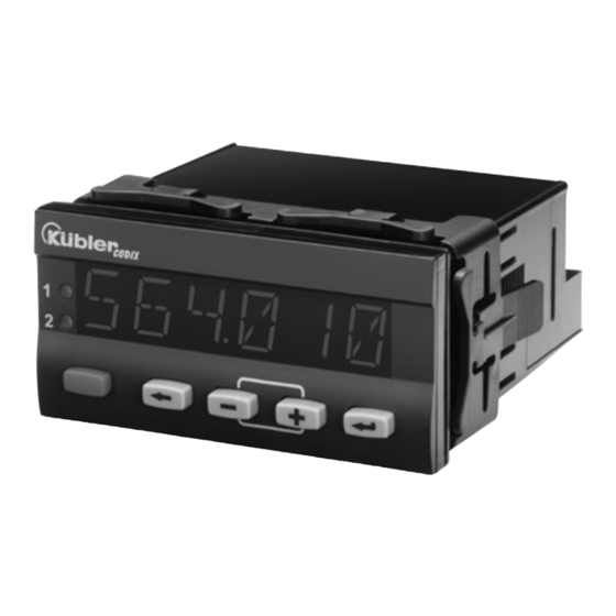
  • Seite 4: Beschreibung

    Beschreibung Digitale Anzeige zur Darstellung von Messwerten sowie zur Überwachung von Grenzwerten im industriellen Einsatzbereich. 6-stellige 14-Segment-LED-Anzeige, 14 mm, zur Messwertanzeige und Dialogführung • Zuschaltbare Laufschrift als Hilfetext • Sprache für den Hilfetext in Deutsch oder Englisch wählbar • Signaleingang für Thermoelemente J, K, N, R, S, T, E, B oder Sensoren im mV-Bereich •...
  • Seite 5: Blockschaltbild

    Blockschaltbild Anschlussbelegung www.kuebler.com Seite 5...
  • Seite 6: Bedienkonzept (Betriebsmode)

    Bedienkonzept (Betriebsmode) Seite 6 www.kuebler.com...
  • Seite 7: Programmierung

    Programmierung Einstieg in das Programmiermenü > 3 sec • Während der Programmierung sind die Relais inaktiv (nicht bestromt). • Beim Verlassen des Programmiermenü über SAVE werden Minimalwert und Maximalwert gelöscht. Einstieg in das Programmiermenü / Funktionsgruppe wählen / Programmiermenü verlassen www.kuebler.com Seite 7...
  • Seite 8 Funktion wählen / Parameter einstellen / Parameter übernehmen Funktionsgruppen Funktion Parameter Werkseinstellungen sind grau hinterlegt. Seite 8 www.kuebler.com...
  • Seite 9: Funktionsgruppen

    Funktionsgruppen Wähle Korrekturwert Hilfetext (Laufschrift) Wertebereich -99.9 … +99.9°C Wertebereich -99,9 … +99,9°F Menü Hilfetext Wähle Auflösung Wähle Hilfetext 0 °C/°F 0.0 °C/°F - eine gestartete Laufschrift kann mit jeder Programmier- taste abgebrochen werden Bei 0.500R Wähle Untere Wähle Sprache für Hilfetext Messbereichsgrenze Wertebereich English...
  • Seite 10 Wähle Auflösung Bei 100 mV 0 °C/°F Wähle Untere 0.0 °C/°F(nicht bei TC.B, R, S) Messbereichsgrenze Wertebereich -105.00 … +105.00 mV alle Wähle Obere Wähle Eingangsfilter Messbereichsgrenze Mit dem Funktion Filter wird Wertebereich angegeben, wie viele -105.00 … +105.00 mV Messzyklen für die gleitende Wähle Dezimalpunkt Mittelwertbildung...
  • Seite 11: Anwender-Linearisierung (±100 Mv / 500 )

    Anwender-Linearisierung (±100 mV / 500 ) Die Funktionen LO.LIM und HI.LIM Menü User-Linearisierung begrenzen den editierbaren Bereich. Wähle User-Linearisierung Der Wert bei HI.LIM muss immer größer Linearisierung Aus sein wie der Wert bei LO.LIM. Linearisierung Ein Wähle Anzahl der Linearisierungspunkte Wertebereich 3 …...
  • Seite 12 Beispiel für Lineare Skalierung Beispiel 1: 0 … 500 0 … 600 Beispiel 2: 0 … 475 = 300 … 900 Beispiel 3: -70 … +80 mV = 750 … 400 Beispiel für Nichtlineare Skalierung LP = Linearisierungspunkt Seite 12 www.kuebler.com...
  • Seite 13: Multifunktions-Taste

    Funktion Multifunktionstaste Programmierung und Defaulteinstellung sperren (MP-Taste) und Multifunktionseingänge In Funktionsgruppe MP.INP Funktion MP.INP1 bzw. MP.INP2 auf LOC.PRG programmieren. (MP-INP) Im Betriebsmode Multifunktions-Eingang 1 bzw. Minimalwertspeicher rücksetzen Multifunktions-Eingang 2 aktivieren. In Funktionsgruppe MP.KEY Funktion RES.MIN Tasten sperren auf ON programmieren. Im Betriebsmode den Minimalwertspeicher (MINIMU) wählen und MP- In Funktionsgruppe MP.INP Funktion MP.INP1 Taste kurz betätigen.
  • Seite 14: Multifunktions-Taste Menü Funktion Mp-Taste

    8.4.1 Multifunktions-Taste 8.4.2 Multifunktions-Eingänge Menü Funktion MP-Taste Menü Funktion MP-Eingänge Wähle Funktion MIN-Wert mit Wähle Funktion MP-Eingang 1 MP-Taste löschen Keine Funktion - nur wenn MIN-Wert in der Anzeige MIN-Wert löschen MAX-Wert löschen MIN- und MAX-Wert löschen Wähle Funktion MAX-Wert mit Ausgang-Latch zurücksetzen MP-Taste löschen - nur wenn Ausgang im...
  • Seite 15: Grenzwertüberwachung

    Grenzwertüberwachung Wähle Ausschalt-Hysterese - nur bei Automatik-Betrieb Menü Alarmausgang 1 Wertebereich 0 … +9999 und DP Wähle Betriebsart Wähle Anzugsverzögerung Wertebereich 0.0 ... 99.9 [sec] Automatik-Betrieb Speicher-Betrieb Wähle Abschaltverzögerung - nicht bei Bandbegrenzung - nur bei Automatik-Betrieb Wertebereich 0.0 ... 99.9 [sec] Wähle Ausgangs-Ansteuerung Bei steigendem Messsignal Bei fallendem Messsignal...
  • Seite 16 Ansteuerung bei steigendem Meßsignal Ansteuerung bei fallendem Meßsignal Seite 16 www.kuebler.com...
  • Seite 17: Ansteuerung Bandbegrenzung

    Ansteuerung Bandbegrenzung Messkreisüberwachung Untere Anzeige- Obere Anzeige- Untere Mess- Obere Mess- Fühler-/Leitungs- bereichsgrenze bereichsgrenze bereichsgrenze bereichsgrenze kurzschluss Fühler-/Leitungs- bruch Messbereich – – – – PT100 ±100 mV Signalisierung blinkend blinkend blinkend blinkend blinkend ( = wird erkannt) 1) nur Fühler-/Leitungsbruch 2) kein Fühler-/Leitungskurzschluss bei 2-Leiter 3) bei Thermoelementen und Pt100 sind die Messbereichsgrenzen fest vorgegeben www.kuebler.com...
  • Seite 18: Technische Daten

    10 Technische Daten 10.1 Allgemeine Daten Eingang 500 Messbereich: 0 … 525 Anzeige: 6-stellige, 14-Segment-LED Auflösung: 15 Bit Ziffernhöhe: 14 mm Messgenauigkeit @ 23°C: typ. 0,1 Datensicherung: > 10 Jahre, EEPROM max. 0,2 Bedienung: 5 Tasten Temperaturdrift: < 100 ppm/K Messstrom: 200 A 10.2...
  • Seite 19: Gerätesicherheit

    10.9 Gerätesicherheit Auslegung nach: EN61010 Teil 1 Schultzklasse: Schutzklasse 2 Einsatzgebiet: Verschmutzungsgrad 2 10.10 Mechanische Daten Gehäuse: Schalttafeleinbaugehäuse nach DIN 43 700, RAL 7021 Abmessungen: 96 x 48 x 102 mm +0,8 +0,6 Schalttafelausschnitt:92 x 45 Einbautiefe: ca. 92 mm inkl. Klemmen Gewicht: ca.
  • Seite 20 12 Hilfstexte PROG. KEINE PROGRAMMIERUNG PROG. PROGRAMMIERUNG STARTEN HLP.TXT. HAUPTMENUE HILFETEXT WAEHLEN HLP.TXT. HILFSTEXTE EIN HLP.TXT HILFETEXT AUS SL.LANG. SPRACHE DEUTSCH SL.LANG. LANGUAGE ENGLISH INPUT. HAUPTMENUE SIGNALEINGANG RANGE TC.J THERMOELEMENT J RANGE TC.K THERMOELEMENT K RANGE TC.N THERMOELEMENT N RANGE TC.B THERMOELEMENT B RANGE...
  • Seite 21: Ueberschreitung Des Anzeigebereichs

    INP.01 EINGANGSWERT 1 DISP.01 ANZEIGEWERT 1 INP.10 EINGANGSWERT 10 DISP.10 ANZEIGEWERT 10 MP.KEY HAUPTMENUE MP-TASTE RES.MIN. FUNKTION MINIMALWERT LOESCHEN AUS RES.MIN. FUNKTION MINIMALWERT LOESCHEN EIN RES.MAX. FUNKTION MAXIMALWERT LOESCHEN AUS RES.MAX. FUNKTION MAXIMALWERT LOESCHEN EIN RES.REL. FUNKTION AUSGANG-LATCH ZURUECKSETZEN AUS RES.REL.
  • Seite 22 Bestellschlüssel 6.56X.X1X.X00 Spannungsversorgung 0 = 90 ... 260 V AC 3 = 10 ... 30 V DC Ausgänge 0 = Relais Front 0 = Kübler-Ausführung A = Neutrale Ausführung Gerätetyp 4 = Temperaturmessgerät 5 = Normsignalmessgerät 6 = DMS-Messgerät Seite 22 www.kuebler.com...
  • Seite 23 CODIX 564 Process Controllers for Temperature Sensors for Thermocouples J, K, N, R, S, T, E, B mV range sensors Resistance thermometers PT100 Resistance sensors up to 500...
  • Seite 24 Table of Contents Preface Safety instructions and Warnings Use according to the intended purpose. Mounting in a control panel Electrical Installation Description Display/Operating elements Block diagram Connections Operating concept (Operating mode) Programming Function Groups Help Texts (running text) Signal inputs User Linearisation (±100 mV / 500 ) Function Multifunction Key (MP-Key) and Multifunction inputs (MP-INP) 9.4.1...
  • Seite 25: Preface

    Preface Mounting in a control panel Please read this instruction manual Mount the device away from heat carefully before installation and start-up. sources and avoid direct contact Please observe all warnings and with corrosive liquids, hot steam or advice, both for your own safety and for similar.
  • Seite 26: Description

    Description Digital panel meter for displaying measured values, as well as monitoring limit values in industrial applications. 6-digit 14-segment LED display, 14 mm, for displaying measured values and dialogs • Running text can be switched on as Help Text • Language for the Help Text selectable as English or German •...
  • Seite 27: Block Diagram

    Block diagram Connections www.kuebler.com Page 5...
  • Seite 28: Operating Concept (Operating Mode)

    Operating concept (Operating mode) Page 6 www.kuebler.com...
  • Seite 29: Programming

    Programming To enter the Programming Menu > 3 sec • During programming the relays are inactive (not energised). • When quitting the programming menu via SAVE, the minimum and maximum vales are reset (cleared). Entering the Programming Menu / Selecting Function Group / Quitting the Programming menu www.kuebler.com Page 7...
  • Seite 30 Selecting Function / Setting Parameters / Accepting Parameters Function Groups Function Parameters Factory settings are highlighted grey. Page 8 www.kuebler.com...
  • Seite 31: Function Groups

    Function Groups Select Correction Value (Offset) Help Texts (running text) Input range -99.9 … +99.9°C Input range -99,9 … +99,9°F Help Text menu Select resolution Select Help Text 0 °C/°F 0.0 °C/°F - a running text that has started can be aborted with any programming key for 0.500R Select lower measuring range...
  • Seite 32 Select resolution for 100 mV 0 °C/°F Select lower measuring range 0.0 °C/°F (not with TC.B, R, S) limit Input range -105.00 … +105.00 mV Select upper measuring range Select Input Filter limit The Filter function shows how Input range many measurement cycles are -105.00 …...
  • Seite 33: User Linearisation (±100 Mv / 500 )

    User Linearisation (±100 mV / 500 ) The functions LO.LIM and HI.LIM limit the editable range. Menu User Linearisation Select User Linearisation The value for HI.LIM must always be greater than the value for LO.LIM. Linearisation OFF Linearisation ON Select number of linearisation (control) points Input range 3 …...
  • Seite 34 Example for linear scaling Example 1: 0 … 500 = 0 … 600 Example 2: 0 … 475 = 300 … 900 Example 3: -70 … +80 mV = 750 … 400 Example for non-linear scaling LP = Linearisation point Page 12 www.kuebler.com...
  • Seite 35: Function Multifunction Key (Mp-Key) And Multifunction Inputs (Mp-Inp)

    Function Multifunction Key Lock-out Programming and Default setting (MP-Key) and Multifunction inputs (MP-INP) In the function group MP.INP, programme the function MP.INP1 or MP.INP2 to LOC.PRG. In Reset MIN value memory the operating mode, activate multifunction input 1 or multifunction input 2. In the function group MP.KEY, programme the function RES.MIN to ON.
  • Seite 36: Multifunction Key

    9.4.1 Multifunction Key 9.4.2 Multifunction Inputs Menu Function MP-Key Menu Function MP-Inputs Select function: Select function MP-Input 1 Reset MIN value with MP-Key No function – only when MIN value Reset MIN value appears in the display Reset MAX value Reset MIN and MAX values Reset Output-Latch Select function:...
  • Seite 37: Limit Value (Alarm) Monitoring

    Limit Value (Alarm) Monitoring Select on-hysteresis Menu Alarm Output 1 Input range Select operating mode 0 … +9999 and DP Select off-hysteresis - only with auto operation Automatic operation Input range Memory latch operation 0 … +9999 and DP - not with band limitation Select on-delay Select Output triggering Input range 0.0 ...
  • Seite 38 Control with incrementing measuring signal Control with decrementing measuring signal Page 16 www.kuebler.com...
  • Seite 39: Monitoring Of Measuring Circuit

    Control with Band Limitation 10 Monitoring of Measuring Circuit Lower Display Upper Display Lower Meas. Upper Meas. Probe or wire Range limit Range limit Range limit Range limit short-circuit Probe or wire break Meas. range – – – – PT100 ±100 mV Indication blinking...
  • Seite 40: Technical Data

    Input 500 11 Technical Data Measuring range: 0 … 525 11.1 General Data Resolution: 15 Bit Measuring accuracy @ 23°C: typ. 0.1 Display: 6-digit, 14 segment LED max. 0.2 Digit height: 14 mm Temperature drift: < 100 ppm/K Data retention: >...
  • Seite 41: Device Safety

    11.9 Device Safety Designed to: EN61010 Part 1 Protection Class: Protection Class 2 Application area: Pollution level 2 11.10 Mechanical Data Housing: Panel mount housing to DIN 43 700, RAL 7021 Dimensions: 96 x 48 x 102 mm +0.8 +0.6 Panel cut-out: x 45 Installation depth:...
  • Seite 42: Help Texts

    13 Help Texts PROG. NO PROGRAMMING PROG. START PROGRAMMING HLP.TXT. MAIN MENU SELECT HELPTEXT HLP.TXT. HELPTEXTS ON HLP.TXT HELPTEXTS OFF SL.LANG. SPRACHE DEUTSCH SL.LANG. LANGUAGE ENGLISH INPUT. MAIN MENU SIGNAL INPUT RANGE TC.J THERMOCOUPLE J RANGE TC.K THERMOCOUPLE K RANGE TC.N THERMOCOUPLE N RANGE...
  • Seite 43 INP.01 INPUT VALUE NO.1 DISP.01 DISPLAY VALUE NO.1 INP.10 INPUT VALUE NO.10 DISP.10 DISPLAY VALUE NO.10 MP.KEY MAIN MENU MP-BUTTON RES.MIN. FUNCTION RESET MIN VALUE OFF RES.MIN. FUNCTION RESET MAX VALUE ON RES.MAX. FUNCTION RESET MIN VALUE OFF RES.MAX. FUNCTION RESET MAX VALUE ON RES.REL.
  • Seite 44: Order Code

    Order code 6.56X.X1X.X00 Supply voltage 0 = 90 ... 260 V AC 3 = 10 … 30 V DC Outputs 0 = Relays Front 0 = Kübler version A = Neutral version Input type 4 = Temperature 5 = Analogue 6 = Strain-gauge Page 22 www.kuebler.com...
  • Seite 45 CODIX 564 Contrôleurs de process pour sondes de température pour Thermocouples J, K, N, R, S, T, E, B pour Sondes dans la plage des mV pour Sonde de température à résistance PT100 pour Sondes à résistance jusqu’à 500...
  • Seite 46 Sommaire Introduction Instructions de sécurité et avertissements Utilisation conforme Montage encastré Installation électrique Description Organes de visualisation/de commande Synoptique Raccordement Concept d’utilisation (mode marche) Programmation Groupes de fonctions Texte d’aide (défilant) Entrées de signal Linéarisation utilisateur (±100 mV / 500 Fonction Touche multifonctions (touche MP) et Entrées multifonctions (MP-INP) 9.4.1 Touche multifonctions...
  • Seite 47: Introduction

    Introduction Instructions de montage Retirer le cadre de fixation de l’appareil. Lisez attentivement ces instructions Introduire l’appareil par l’avant dans la d’utilisation avant le montage et la mise en découpe d’encastrement du panneau et veiller service. Pour votre propre sécurité, ainsi à...
  • Seite 48: Description

    Description Afficheur digital pour l’affichage de valeurs mesurées et pour la surveillance de valeurs limite dans le domaine industriel. Affichage LED à 6 digits de 14 segments, 14 mm, pour l’affichage de valeurs mesurées et le dialogue • avec l’utilisateur Possibilité...
  • Seite 49: Synoptique

    Synoptique Raccordement www.kuebler.com Page 5...
  • Seite 50: Concept D'utilisation (Mode Marche)

    Concept d’utilisation (mode marche) MODE MARCHE Val. mesurée courante Valeur min. Valeur max. Version de l’appareil pdt 2s Version de logiciel pdt 2s TOUCHE MP FONCTION DE LA TOUCHE, voir 9.4 Réglage valeur limite 1 Valeur limite 1 Réglage valeur limite 2 Valeur limite 2 Réduction de la valeur Augmentation de la valeur...
  • Seite 51: Programmation

    Programmation Appel du menu de programmation > 3 sec • Les relais sont inactifs (non alimentés) pendant la programmation). • Les valeurs minimale et maximale sont effacées lorsque le menu de programmation est refermé avec SAVE. Appel du menu de programmation / Sélection du groupe de fonctions / Sortie du menu de programmation MODE MARCHE www.kuebler.com...
  • Seite 52 Sélection de la fonction / Réglage des paramètres / Prise en compte des paramètres Groupes de fonctions Fonction Paramètre Les réglages d’usine sont indiqués sur fond gris. Page 8 www.kuebler.com...
  • Seite 53: Groupes De Fonctions

    Groupes de fonctions Valeur de correction Texte d’aide (défilant) Plage de valeurs -99.9…+99.9°C Plage de valeurs -99,9…+99,9°F Menu Textes d’aide Résolution Textes d’aide 0 °C/°F 0.0 °C/°F Activés - un texte défilant peut être interrompu en pressant sur Pour 0.500R n’importe quelle touche de Limite inférieure de la plage de programmation...
  • Seite 54 Pour 100 mV tous Limite inférieure de la plage de Filtre d’entrée mesure La fonction Filtre permet de Plage de valeurs déterminer le nombre de -105.00 … +105.00 mV cycles de mesure à utiliser Limite supérieure de la plage pour la formation de la de mesure moyenne flottante.
  • Seite 55: Linéarisation Utilisateur (±100 Mv / 500 )

    Linéarisation utilisateur (±100 mV / 500 ) Menu Linéarisation Les fonctions LO.LIM et HI.LIM délimitent utilisateur la zone éditable. Linéarisation utilisateur La valeur de HI.LIM doit toujours être Linéarisation désactivée supérieure à la valeur de LO.LIM. Linéarisation activée Nombre de points de linéarisation Plage de valeurs 3 …...
  • Seite 56 Exemple d’une échelle linéaire Exemple 1 : 0 … 500 = 0 … 600 Exemple 2 : 0 … 475 = 300 … 900 Exemple 3 : -70 … +80 mV = 750 … 400 Affichage Exemple 2 Exemple 3 Exemple 1 Valeur d'entrée...
  • Seite 57: Fonction Touche Multifonctions (Touche Mp) Et Entrées Multifonctions (Mp-Inp)

    Fonction Touche multifonctions Blocage du réglage des valeurs limite (touche MP) et Entrées Dans le groupe de fonctions MP.INP, multifonctions (MP-INP) programmer la fonction MP.INP1 ou MP.INP2 à LOC.ALR. En mode marche, activer l’entrée Remise à zéro de la mémoire de la valeur multifonctions programmée, 1 ou 2.
  • Seite 58: Touche Multifonctions

    9.4.1 Touche multifonctions 9.4.2 Entrées multifonctions Menu Fonction touche MP Menu Fonction entrées MP Fonction d’effacement de la Fonction Entrée MP 1 valeur MIN à l’aide de la Sans fonction touche MP - uniquement lorsque la valeur Effacement de la valeur MIN MIN est affichée Effacement de la valeur MAX Désactivée...
  • Seite 59: Surveillance Des Valeurs Limite

    Surveillance des valeurs limite Sortie inactive en cas d’alarme Hystérèse d’activation Menu Sortie d’alarme 1 Plage de valeurs Sélection du mode opératoire 0 … +9999 et DP Désactivée Hystérèse de désactivation Réinitialisation automatique du - uniquement en mode relais à la fin de l’alarme réinitialisation automatique Pas de réinitialisation Plage de valeurs...
  • Seite 60 Commande par signal de mesure croissant Tempo ON Tempo OFF Point de commutation ON Valeur hystérèse ON Valeur limite Valeur hystérèse OFF Point de commutation OFF Valeur du process Avec hystérèse / avec tempo. Sans hystérèse / sans tempo. Avec hystérèse / avec tempo. Sans hystérèse / sans tempo.
  • Seite 61: Surveillance Du Circuit De Mesure

    Commande par limitation de bande passante Tempo ON Tempo ON Tempo OFF Tempo OFF Tempo OFF Point de commutation HAUT Valeur hystérèse ON Valeur limite Valeur hystérèse OFF Point de commutation BAS Valeur du process Avec tempo. Sans tempo. Avec tempo. Sans tempo.
  • Seite 62: Caractéristiques Techniques

    11 Caractéristiques techniques 11.1 Caractéristiques générales Entrée 500 Plage de mesure : 0 … 525 Affichage : LED, 6 digits de 14 segments Résolution : 15 bits Hauteur des chiffres:14 mm Précision de mesure @ 23°C : typ. 0,1 Sauvegarde des >...
  • Seite 63: Cem

    11.8 Résistance aux perturbations : EN61000-6-2 11.11 Raccordements avec lignes de signal et de Tension d’alimentation et sorties: commande blindées Bornes à visser, 8 bornes, pas 5,00 Emission de perturbations : EN55011 classe B Section des conducteurs : max. 2,5 mm² 11.9 Sécurité...
  • Seite 64: Textes D'aide

    13 Textes d’aide PROG. NO PROGRAMMING PROG. START PROGRAMMING HLP.TXT. MAIN MENU SELECT HELPTEXT HLP.TXT. HELPTEXTS ON HLP.TXT HELPTEXTS OFF SL.LANG. SPRACHE DEUTSCH SL.LANG. LANGUAGE ENGLISH INPUT. MAIN MENU SIGNAL INPUT RANGE TC.J THERMOCOUPLE J RANGE TC.K THERMOCOUPLE K RANGE TC.N THERMOCOUPLE N RANGE...
  • Seite 65 INP.01 INPUT VALUE NO.1 DISP.01 DISPLAY VALUE NO.1 à INP.10 INPUT VALUE NO.10 DISP.10 DISPLAY VALUE NO.10 MP.KEY MAIN MENU MP-BUTTON RES.MIN. FUNCTION RESET MIN VALUE OFF RES.MIN. FUNCTION RESET MAX VALUE ON RES.MAX. FUNCTION RESET MIN VALUE OFF RES.MAX. FUNCTION RESET MAX VALUE ON RES.REL.
  • Seite 66: Référence De Commande

    Référence de commande 6.56X.X1X.X00 Tension d’alimentation 0 = 90 ... 260 V AC 3 = 10 ... 30 V DC Sorties 0 = Relais Façade 0 = Exécution Kübler- A = Exécution neutre Type d’appareil 4 = Mesure de température 5 = Mesure de signaux normalisés 6 = Mesure par jauge de...
  • Seite 67 CODIX 564 Controllori di processo per sonde di temperatura per Termocoppie J, K, N, R, S, T, E, B Sonde nell'area dei mV Sonde di temperatura a resistenza PT100 Sonde a resistenza fino a 500...
  • Seite 68 Sommario Introduzione Istruzioni di sicurezza e avvertenze Utilizzo conforme Montaggio incassato Installazione elettrica Descrizione Display/Elementi di controllo Schema a blocchi Collegamento Concetto di utilizzo (modalità di funzionamento) Programmazione Gruppi funzioni Testi di aiuto (scorrenti) Entrate di segnale Linearizzazione utente (±100mV/500 ) Funzione tasto multifunzione (tasto MP) e entrate multifunzione (MP-INP) 9.4.1 Tasto multifunzione...
  • Seite 69: Introduzione

    Montaggio incassato Introduzione Montare l’apparecchio lontano da Prima di procedere al montaggio ed alla ogni fonte di calore ed evitare ogni messa in funzione, leggere contatto diretto con liquidi corrosivi, attentamente le presenti istruzioni vapore caldo o sostanze simili. PRECAUZIONE d’uso.
  • Seite 70: Descrizione

    Descrizione Display digitale per la visualizzazione di valori di misurazione e per la sorveglianza di valori limite nell'area di utilizzo industriale. Display LED a 14 segmenti da 6 cifre, 14 mm, per la visualizzazione di valori di misurazione e la guida •...
  • Seite 71: Schema A Blocchi

    Schema a blocchi solo per la versione AC Versione DC: Versione AC: Valore limite 1 interno Valore limite 2 Collegamento www.kuebler.com Pagina 5...
  • Seite 72: Concetto Di Utilizzo (Modalità Di Funzionamento)

    Concetto di utilizzo (modalità di funzionamento) MODALITA' DI FUNZIONAMENTO Val. di misura attuale Valore min. Valore max. Versione apparecchio per 2s Versione software per 2s TASTO MP FUNZIONE DEL TASTO, vedi 9.4 Regolazione val. limite 1 Valore limite 1 Regolazione val. limite 2 Valore limite 2 Riduzione del valore Aumento del valore...
  • Seite 73: Programmazione

    Programmazione Entrata nel menu di programmazione > 3 sec • Durante la programmazione i relè non sono attivi (non alimentati). • Quando si lascia il menu di programmazione attraverso SAVE, il valore minimo e quello massimo vengono cancellati. Entrata nel menu di programmazione / Scelta del gruppo di funzioni / Uscita del menu di programmazione MODALITA’...
  • Seite 74 Scelta della funzione / Impostazione dei parametri / Acquisizione dei parametri Gruppo funzioni Funzione Parametro Selezione del parametro Regolazione del valore Riduzione del valore Aumento del valore Selezione del digit Selezione del parametro Le impostazioni di fabbrica presentano uno sfondo grigio. Pagina 8 www.kuebler.com...
  • Seite 75: Gruppi Funzioni

    Valore di correzione Gruppi funzioni Campo di valori -99.9 … +99.9°C Campo di valori -99,9 … +99,9°F Testi di aiuto (scorrenti) Risoluzione Menu Testi di aiuto 0 °C/°F 0.0 °C/°F Testi di aiuto Attivati - un testo scorrente avviato può essere interrotto con ogni Per 0.500R tasto di programmazione Limite inferiore dell'intervallo di...
  • Seite 76 Risoluzione 0 °C/°F Per 100MV 0.0 °C/°F(non per TE.B, R, S) Limite inferiore dell'intervallo di misurazione Campo di valori tutti -105.00 … +105.00 mV Filtro di entrata Limite superiore dell'intervallo Con la funzione filtro si indica di misurazione quanti cicli di misurazione Campo di valori vengono impiegati per la -105.00 …...
  • Seite 77: Linearizzazione Utente (±100Mv/500 )

    -199999 … +999999 e DP Linearizzazione utente (±100mV/500 ) Menu Linearizzazione utente Le funzioni LO.LIM e HI.LIM limitano l'area editabile. Linearizzazione utente Linearizzazione disattivata Il valore di HI.LIM deve essere sempre più grande rispetto al valore di LO.LIM. Linearizzazione attivata Numero dei punti di linearizzazione Campo di valori 3 …...
  • Seite 78 Esempio di scala lineare Esempio 1: 0 … 500 = 0 … 600 Esempio 2: 0 … 475 = 300 … 900 Esempio 3: -70 … +80mV = 750 … 400 Display Esempio 2 Esempio 3 Esempio 1 Valore d’entrata Esempio di scala non lineare Display Esempio 2...
  • Seite 79: Funzione Tasto Multifunzione (Tasto Mp) E Entrate Multifunzione (Mp-Inp)

    Blocco dell'impostazione dei valori limite Funzione tasto multifunzione Nel gruppo funzioni MP.INP, programmare la (tasto MP) e entrate funzione MP.INP1 oppure MP.INP2 su multifunzione (MP-INP) LOC.ALR. In modalità funzionamento, attivare l'entrata multifunzione programmata, 1 o 2. Azzeramento della memoria del valore minimo Blocco della programmazione e Nel gruppo funzioni MP.KEY, programmare la...
  • Seite 80: Tasto Multifunzione

    9.4.1 Tasto multifunzione 9.4.2 Entrate multifunzione Menu Funzione Tasto MP Menu Funzione Entrate MP Funzione di cancellazione del Funzione Entrata MP 1 valore MIN con il tasto MP Nessuna funzione - solo con valore MIN nel display Cancellazione del valore MIN Disattivato Cancellazione del valore MAX Attivato...
  • Seite 81: Sorveglianza Dei Valori Limite

    Stato in caso di allarme Sorveglianza dei valori limite In caso di allarme: uscita attiva Menu Uscita d’allarme 1 In caso di allarme: uscita inattiva Tipo di esercizio Isteresi di attivazione Disattivato Campo di valori Ripristino automatico del relè 0 … +9999 e DP alla fine dell’alarme Isteresi di disattivazione Senza ripristino automatico del...
  • Seite 82 Comando con segnale di misurazione crescente Ritardo ON Ritardo OFF Punto di commutazione ON Valore isteresi ON Valore limite Valore isteresi OFF Punto di commutazione OFF Valore del processo Con isteresi / con ritardo Senza isteresi / senza ritardo Con isteresi / con ritardo Senza isteresi / senza ritardo Tasto multifunzione o entrata multifunzione...
  • Seite 83: Sorveglianza Del Circuito Di Misurazione

    Comando con limitazione di banda passante Ritardo ON Ritardo ON Ritardo OFF Ritardo OFF Ritardo OFF Punto di commutazione ALTO Valore isteresi ON Valore limite Valore isteresi OFF Punto di commutazione BASSO Valore del processo Con ritardo Senza ritardo Con ritardo Senza ritardo Tempo 10 Sorveglianza del circuito di misurazione...
  • Seite 84: Dati Tecnici

    Resistenza dei cavi max. 25 per cavo 11 Dati tecnici Entrata 500 11.1 Dati generali Campo di misurazione 0 … 525 Display LED a 6 cifre e 14 segmenti Risoluzione 15 bit Altezza delle cifre 14 mm Precisione di misurazione @ 23°C tip.
  • Seite 85: Cem

    11.8 11.11 Collegamenti Resistenza alle interferenze: EN61000-6-2 Tensione di alimentazione e uscite: con linee di comando e Morsetti a vite, 8 poli, passo 5, 00 di segnale schermate Sezione dei conduttori, max. 2,5 mm² Emissione di interferenze: EN55011 Classe B Entrate di segnale e di comando: 11.9 Sicurezza degli apparecchi...
  • Seite 86: Testi Di Aiuto

    13 Testi di aiuto PROG. NO PROGRAMMING PROG. START PROGRAMMING HLP.TXT. MAIN MENU SELECT HELPTEXT HLP.TXT. HELPTEXTS ON HLP.TXT HELPTEXTS OFF SL.LANG. SPRACHE DEUTSCH SL.LANG. LANGUAGE ENGLISH INPUT. MAIN MENU SIGNAL INPUT RANGE TE.J THERMOCOUPLE J RANGE TE.K THERMOCOUPLE K RANGE TE.N THERMOCOUPLE N...
  • Seite 87 NUM.PNT. NUMBER OF LINEARIZATION POINTS INP.01 INPUT VALUE NO.1 DISP.01 DISPLAY VALUE NO.1 INP.10 INPUT VALUE NO.10 DISP.10 DISPLAY VALUE NO.10 MP.KEY MAIN MENU MP-BUTTON RES.MIN. FUNCTION RESET MIN VALUE OFF RES.MIN. FUNCTION RESET MAX VALUE ON RES.MAX. FUNCTION RESET MIN VALUE OFF RES.MAX.
  • Seite 88: Codice Di Ordinazione

    Codice di ordinazione 6.56X.X1X.X00 Tensione di alimentazione 0 = 90 .. 260 VAC 3 = 10 .. 30 VDC Uscite 0 = Relè Frontale 0 = Versione Kübler A = Versione neutrale Tipo di apparecchio 4 = Misurazione di temperatura 5 = Misurazione di segnali normalizzati 6 = Misurazione con...
  • Seite 89 CODIX 564 Controlador de proceso para sondas de temperatura para Termopares J, K, N, R, S, T, E, B para Sondas en la gama de los mV para Sondas de temperatura de para resistencia PT100 para Sondas de resistencia hasta 500 Clave de pedido 6.56X.X1X.X00...
  • Seite 90 Índice Introducción Observaciones de seguridad yadvertencia Uso conforme a su finalidad Montaje en el cuadro de mando Instalación eléctrica Descripción Órganos de visualización/de mando Diagrama funcional Conexiones Concepto de manejo (modo de servicio) Programación Grupos de funciones Texto de ayuda (texto móvil) Entradas de señal Linealización usuario (±100 mV / 500 Función Tecla multifunción (Tecla MP) y Entradas multifunción (MP-INP)
  • Seite 91: Introducción

    Introducción Montaje en el cuadro de mando Antes del montaje y de la puesta en Monte el aparato lejos de fuentes servicio, lea estas instrucciones de de calor y evite el contacto directo manejo. Por su propia seguridad y la con líquidos corrosivos, vapor del servicio, respete todas las caliente o similares...
  • Seite 92: Descripción

    Descripción Visualizador digital para la representación de valores de medición así como la supervisión de valores límite en el ámbito de empleo industrial. Visualizador LED de 6 dígitos, 14 segmentos, 14 mm, para la visualización de valores de medición y el •...
  • Seite 93: Diagrama Funcional

    Diagrama funcional Conexiones www.kuebler.com Página 5...
  • Seite 94: Concepto De Manejo (Modo De Servicio)

    Concepto de manejo (modo de servicio) MODO DE SERVICIO Val. medido corriente Valor mín. Valor máx. Versión apataro durante 2s Versión software durante 2s TECLA MP FUNCIÓN DE LA TECLA, ver 9.4 Ajuste valor límite 1 Valor límite 1 Ajuste valor límite 2 Valor límite 2 Reducción del valor Aumento del valor...
  • Seite 95: Programación

    Programación Acceso al menú de programación >3 seg • Durante la programación están inactivos los relés (no energizado). • Al salir del menú de programación con SAVE se borra el valor mínimo y el máximo Acceso al menú de programación / Elección del grupo de funciones / Salida del menú de programación MODO DE SERVICIO www.kuebler.com...
  • Seite 96 Elección de la función / Ajuste de los parámetros/ Confirmación de los parámetros Grupo de funciones Función Parámetro Los valores de fábrica se indican en gris. Página 8 www.kuebler.com...
  • Seite 97: Grupos De Funciones

    Grupos de funciones Valor de corrección Texto de ayuda (texto móvil) Intervalo de valores -99.9 … +99.9°C Menú del texto de ayuda Intervalo de valores -99,9 … +99,9°F Texto de ayuda Resolución Activado 0 °C/°F - un texto móvil puede 0.0 °C/°F terminarse con cualquiera tecla de programación...
  • Seite 98 Resolución 0 °C/°F En 100 mV 0.0 °C/°F(no en TC.B, R, S) Límite inferior del intervalo de medición Intervalo de valores todo -105.00 … +105.00 mV Filtro de entrada Límite superior del intervalo de Con la función filtro se medición determinará...
  • Seite 99: Linealización Usuario (±100 Mv / 500 )

    Linealización usuario Valor de visualización final (±100 mV / 500 ) para INP.HI. Intervalo de valores Menú Linealización usuario -199999 … +999999 y DP Linealización usuario Linealización desactivada Linealización activada Las funciones LO.LIM y HI.LIM limitan la Número de puntos de parte editable.
  • Seite 100 Ejemplo para una escala lineal Ejemplo 1: 0 … 500 = 0 … 600 Ejemplo 2: 0 … 475 = 300 … 900 Ejemplo 3: -70 … +80 mV = 750 … 400 Pantalla Ejemplo 2 Ejemplo 3 Ejemplo 1 Valor de entrada Ejemplo para una escala no lineal...
  • Seite 101: Función Tecla Multifunción (Tecla Mp) Y Entradas Multifunción (Mp-Inp)

    Función Tecla multifunción Bloquear la programación y el ajuste por defecto (Tecla MP) y Entradas multifunción (MP-INP) Programe en el grupo de funciones MP INP la función MP INP1 o MP INP2 en LOC.PRG. En Puesta a cero de la memoria del valor el modo de servicio, active brevemente la mínimo entrada multifunción programada, 1 o 2.
  • Seite 102: Tecla Multifunción

    9.4.1 Tecla Multifunción 9.4.2 Entradas Multifunción Menú Función Tecla MP Menú Función Entradas MP Función Borrar el valor MIN Función Entrada MP 1 con la tecla MP Sin función - sólo cuando el valor MIN esté en la pantalla Borrar el valor MIN Desactivado Borrar el valor MAX Activado...
  • Seite 103: Supervisión De Los Valores Limite

    Supervisión de los valores limite Histéresis de adesctivación -sólo en modo reinicialización auto. Menú salida de alarma 1 Intervalo de valores 0 … +9999 y DP Modo de funcionamiento Retardo a la activación Desactivado Intervalo de valores 0.0…99.9 [seg] Modo reinicialización automática Modo sin reinicialización auto.
  • Seite 104 Mando con señal de medición creciente Retardo ON Retardo OFF Punto de conmutación ON Valor histéresis ON Valor límite Valor histéresis OFF Punto de conmutación OFF Valor del proceso Con histéresis / con retardo Sin histéresis / sin retardo Con histéresis / con retardo Sin histéresis / sin retardo Tecla multifonción o entrada multifonción...
  • Seite 105: Supervisión En El Circuito De Medición

    Mando con limitación de banda Retardo ON Retardo ON Retardo OFF Retardo OFF Retardo OFF Punto de comutación ALTO Valor histéresis ON Valor límite Valor histéresis OFF Punto de comutación BAJO Valor del proceso Con retardo Sin retardo Con retardo Sin retardo Tiempo 10 Supervisión en el circuito de medición...
  • Seite 106: Datos Técnicos

    11 Datos técnicos Entrada 500 Intervalo de medición: 0 … 525 11.1 Datos generales Resolución: ±15 bits Visualización: LED, 6 dígitos, 14 segmentos Precisión de medida a 23°C: tip. 0,1 Tamaño de los dígitos: 14 mm máx. Salvaguarda de datos: > 10 Años, EEPROM Deriva de temperatura: <...
  • Seite 107: Cem

    11.8 11.11 Conexiones Inmunidad a interferencias: EN61000-6-2 Tensión de alimentación y salidas: con líneas de señal y Bornes roscados, 8 polos, paso 5,00 de mando blindadas Sección de conductor, máx. 2,5 mm² Emisión de interferencias: EN55011 Clase B Entradas de señal y de mando: 11.9 Seguridad del aparato Bornes roscados, 9 polos, paso 3,50...
  • Seite 108: Textos De Ayuda

    13 Textos de ayuda PROG. NO PROGRAMMING PROG. START PROGRAMMING HLP.TXT. MAIN MENU SELECT HELPTEXT HLP.TXT. HELPTEXTS ON HLP.TXT HELPTEXTS OFF SL.LANG. SPRACHE DEUTSCH SL.LANG. LANGUAGE ENGLISH INPUT. MAIN MENU SIGNAL INPUT RANGE TC.J THERMOCOUPLE J RANGE TC.K THERMOCOUPLE K RANGE TC.N THERMOCOUPLE N...
  • Seite 109 INP.01 INPUT VALUE NO.1 DISP.01 DISPLAY VALUE NO.1 hasta INP.10 INPUT VALUE NO.10 DISP.10 DISPLAY VALUE NO.10 MP.KEY MAIN MENU MP-BUTTON RES.MIN. FUNCTION RESET MIN VALUE OFF RES.MIN. FUNCTION RESET MAX VALUE ON RES.MAX. FUNCTION RESET MIN VALUE OFF RES.MAX. FUNCTION RESET MAX VALUE ON RES.REL.
  • Seite 110 Clave de pedido 6.56X.X1X.X00 Tensión de alimentación 0 = 90 ... 260 V AC 3 = 10 ... 30 V DC Salidas 0 = Relé Frente 0 = Versión Kübler A = Versión neutral Tipo de aparato 4 = Medición de temperatura 5 = Medición de señales normalizadas...

Inhaltsverzeichnis