Herunterladen Inhalt Inhalt Diese Seite drucken
bürkert 8041 Bedienungsanleitung

bürkert 8041 Bedienungsanleitung

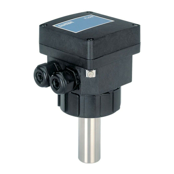
Magnetisch-induktiver durchflussmesser
Vorschau ausblenden Andere Handbücher für 8041:
Inhaltsverzeichnis

Werbung

Verfügbare Sprachen

Verfügbare Sprachen

8041
MAGNETISCH-INDUKTIVER
DURCHFLUSSMESSER
Bedienungsanleitung
© Bürkert 2004
Technische Änderung vorbehalten

Werbung

Inhaltsverzeichnis
loading

Inhaltszusammenfassung für bürkert 8041

  • Seite 1 8041 MAGNETISCH-INDUKTIVER DURCHFLUSSMESSER Bedienungsanleitung © Bürkert 2004 Technische Änderung vorbehalten...
  • Seite 2: Inhaltsverzeichnis

    6.6 Abmessungen ............................36 6.7 Beschreibung des Typenschilds ....................... 36 ANHANG ....................................37 7.1 Bestell-Tabelle ............................37 7.1.1 Vollständige Produkte ............................... 37 7.1.2 Zubehör und Ersatzteile ............................37 7.2 Durchfluss - Geschwindigkeit -Fittingnennweite-Diagramm ............38 7.3 Anschlussbeispiele ..........................39 EG-Konformitäts-Erklärung .......................... 43 8041...
  • Seite 3: Einführung

    - Schützen Sie das Gerät von elektromagnetischen Störungen, von Ultraviolett- bestrahlung und, bei einer Außenanwendung, von den Wetterbedingungen. - Wenn diese Anweisungen nicht befolgt werden und das Gerät nicht entsprechend den Angaben verwendet wird, wird keinerlei Haftung übernommen und die Garantie für das Gerät erlischt. 8041...
  • Seite 4: Beschreibung

    - Der Filtertyp der Durchfluss-Messungen 1.4 VERHÄLTNIS ZWISCHEN GESCHWINDIGKEIT UND DURCHFLUSS - K-FAKTOR Der 8041 misst eine Mediums-Geschwindigkeit (in m/s) und wandelt diese in ein Strom (in mA) und eine Frequenz (in Hz) um. Der K-Faktor beschreibt den linearen Zusammenhang zwischen Ausgangssignal und dem...
  • Seite 5 EINFÜHRUNG Beispiel Sei ein 8041 in ein Edelstahl-Fitting S020 von DN50 eingesetzt: = 11,24 Fitting Das Ausgewählte Messbereichende ist 5 m/s. Es ergibt sich folgenden K-Faktor K zur Umwandlung der Ausgangsfequenz f in ein Durchfluss: 200 = 17,79 11,24 Es ergibt sich folgenden K-Faktor K...
  • Seite 6: Quick Start

    QUICK START Dieser Abschnitt bietet eine umfassende Anleitung für Installation und Betrieb des Gerätes, die Ihnen die Inbetriebnahme de Durchflussmessers 8041 erleichtert. Gerät auspacken Nein Wenden Sie sich an Bestell-Nr Ihren Bürkert- Zwischenhändler 4 Schrauben losschrauben Wählen Sie die Netzfrequenz Siehe 3.2...
  • Seite 7 2 m/s und auf? < 10 m/s Siehe 3.6 Relais-Ausgangsdaten programmieren Nein Siehe 5.1, Fehleran- Siehe 3.1 Überprüfen, ob die grüne Lampe einmal blinkt zeige Deckel gemäß Montageausrichtung zurücksetzen (siehe Foto) und 4 Schrauben festschrauben Das Gerät ist betriebsbereit 8041...
  • Seite 8: Bedienung

    Messungen, Messbereich) im Abgleich-Modus: Lampe blinkt 1 mal = 1% - Schalter 6: nicht verwendet des Messbereichendes (oder 1 Sekunde) Setzen Sie immer den Deckel wie im neben- stehenden Foto angezeigt zurück; Schrauben Sie die 4 Schrauben über Kreuz fest. 8041...
  • Seite 9 * das Gerät kommt automatisch zum Lese-Modus der gemessenen Geschwindigkeit zurück, wenn kein Druck auf den Drucktaster während 10 s entsteht. Bargraph Grüne Anzeige blinkt ..1 bis 5 mal Lampe aus Rote Anzeige aus Lampe leuchtet Drucktaster Rote Anzeige leuchtet Lampe blinkt 8041...
  • Seite 10 BEDIENUNG 8041...
  • Seite 11: Auswahl Der Netzfrequenz

    60 Hz 3.3 AUSWAHL DES FILTERTYPS Mit der Filterung können die Durchflussschwankungen auf dem Bargraph und auf den Strom- und Frequenzausgängen abgeschwächt werden. Der Durchflussmesser 8041 kann ohne oder mit Filterung arbeiten. Mit Schalter 2 kann die Filterung aktiviert werden:...
  • Seite 12 1 2 3 4 5 6 7 8 9 10 nicht siehe § 3.1. - Auf den Drucktaster drücken und halten: Nach 2 s Messbereichende-Kalibrierung leuchtet die rote Anzeige auf (Abgleich-Modus) und der Bargraph zeigt die Funktionen Nullpunktabgleich und Messbereichende-Kalibrierung wechselnd an. 8041...
  • Seite 13: Nullpunktabgleich

    0 bis 5 m/s 0 bis 10 m/s 0 bis kalibriertes Messbereichende (zwischen 2 und 10 m/s) Nach Änderung des Messbereichs lassen sich die für die niedrigen und hohen Schalt- schwellen programmierten Prozentsätze auf das neu ausgewählte Messbereichende anwenden. 8041...
  • Seite 14: Messbereichende-Kalibrierung

    Messbereichende + 20% Bargraphstatus Falls keiner vorbestimmten Messwert für Ihre Applikation geeignet ist, kann der Sensor 8041 mit dem Mess- bereichende der Applikation kalibriert werden. Der Minuswert des Messbereichs ist 0 m/s. - Stellen Sie Schalter 4 und 5 auf ON.
  • Seite 15: Einstellen Der Relaisausgangsdaten

    - Die niedriege Schaltschwelle, als Prozentsatz des Messbereichendes - Die obere Schaltschwelle, als Prozentsatz des Messbereichendes - Die Schaltverzögerungszeit, von 0 bis 100 s. Die Funktionsweise des Relais, entweder stromlos geöffnet (NO) oder stromlos geschlossen (NC), wird durch Anschließen des Relais an die Elektronikplatine bestimmt. 8041...
  • Seite 16: Schaltmodus Des Relais-Ausgangs

    Zwei Schaltmodi des Relais sind vorhanden: Der Fenster- und der Hysterese-Modus. - Bei dem Fenster-Modus erfolgt die Statusänderung des Relais bei Erkennung jeder Schaltschwelle: Fenster-Modus Fenster-Modus (NO-angeschlossenes Relais) (NC-angeschlossenes Relais) Relais-Ausgang Relais-Ausgang aktiv aktiv inaktiv inaktiv Obere Niedrige Obere Niedrige Schaltschwelle Schaltschwelle 8041...
  • Seite 17 Funktion auszuwählen und automatisch zum Lese Modus der gemessenen Geschwindigkeit zurüc zukommen. ♦ auf den Drucktaster drücken und halten, um eine andere Funktion auszuwählen. ♦ 10 s lang warten, um zum Lese-Modus der gemessenen Geschwindigkeit zurückzukommen, ohne die angezeigte Funktion auszuwählen. 8041...
  • Seite 18: Einstellung Der Niedrigen Schaltschwelle

    Messbereichendes Geschwindigkeit zurückzukommen, ohne den angezeigten 3te Lampe blinkt 4 mal = 4% des Wert zu bestätigen. Messbereichendes Der Bargraph zeigt einen eingestellten Wert von 24% des Messbereichendes an, d.h. 2,4 m/s bei einem ausgewählten Messbereichende von 10 m/s. 8041...
  • Seite 19: Einstellung Der Oberen Schaltschwelle

    Geschwindigkeit zurückzukommen, ohne den angezeigten 9te Lampe blinkt 2 mal = 2% des Wert zu bestätigen. Messbereichendes Der Bargraph zeigt einen eingestellten Wert von 82% des Messbereichendes an, d.h. 8,2 m/s bei einem ausgewählten Messbe- reichende von 10 m/s. 8041...
  • Seite 20: Einstellung Der Schaltverzögerung

    10 s lang warten, um zum Lese-Modus der gemessenen Geschwindigkeit zurückzukommen, ohne den angezeigten 100 s Wert zu bestätigen. 5 leuchtende Lampen = 50 s 6te Lampe blinkt 2 mal = 2 s Der Bargraph zeigt eine Vezöge- rung von 52 s. 8041...
  • Seite 21: Installation

    4.1 RICHTLINIEN FÜR DIE INSTALLATION 4.1.1 Temperatur-Druck Diagramm Betriebs-Temperatur und -Druck des Sensors und des verwendeten Fittings sind begrenzt. Folgendes Diagramm zeigt den Anwendungsbereich von der Kombination Sensor+Fitting je nach Fittingwerkstoff: Bei Verwendung eines 8041 mit Edelstahl-Sensor Anwendungsbereich P (bar) Metall (PN16) PVDF...
  • Seite 22: Einbau

    Es ist ratsam, den Durchflussmesser, wie im Schaubild ge- zeigt in einem Winkel von 45° zum horizontalen Mittelpunkt 45° des Rohrs zu montieren, um eventuelle Niederschläge auf den Elektroden zu vermeiden und damit die Messungen nicht durch Luftblasen 45° gefälscht werden. 8041...
  • Seite 23 FS = x,xxx Strömungsrichtung 3 x DN 10 x DN Vergewissern Sie sich bitte, dass der Rohrleitungsaufbau nicht die Bildung von Luftblasen oder -einschlüssen im Medium begünstigt, da diese Messfehler verursachen. Strömungs- richtung Strömungs- richtung Richtig Falsch Richtig Falsch 8041...
  • Seite 24: Installation

    INSTALLATION 4.2 INSTALLATION Der Durchflussmesser 8041 kann mit speziell entwickelten Bürkert-Fittings S020 in Rohrleitungen montiert werden. Beim Einbau des Sensors 4 beachten Sie die in Abschnitt 4.1 und in der Bedienungs- anleitung des Fittings angegebenen Montageanweisungen. Dann: - Die Überwurfmutter 3 auf das Fitting 4 schieben und den Kunststoffring 2 in die Führungsbuchse 5 einrasten lassen.
  • Seite 25 Metallische Apparate (Ventil, Pumpe,...) Für Kunststoffrohr-Anwendungen (*) oder in die Rohrleitung eingesetzte metallische Teile. (**) Ist keine direkte Erdung möglich, schließen Sie einen 100 nF / 50 V -Kondensator zwischen dem negativen Anschluss der Versorgungsquelle und der Erde an. 8041...
  • Seite 26: Elektrischer Anschluss

    Veschluss verstopft werden, um die Dichtheit des Durch- flussmessers zu vergewissern. Die Kabelverschraubung aufschrauben dann den Verschluss einschieben und die Kabelverschraubung wieder fest- schrauben. Setzen Sie immer den Deckel wie im neben- stehenden Foto angezeigt zurück; Schrauben Sie die 4 Schrauben über Kreuz fest. 8041...
  • Seite 27: Anschluss Des 4-20 Ma-Stromausgangs

    INSTALLATION 4.4.1 Anschluss des 4-20 mA-Stromausgangs Der Stromausgang des 8041 kann an ein externes Gerät (SPS,...) mit 4-20-mA-Eingang als Quelle oder Senke angeschlossen werden. Stellen Sie den Senke / Quelle-Schalter unter spannungslosem Gerät in Ab- hängigkeit des Anschlusses richtig an.
  • Seite 28: Anschluss Des Frequenzausgangs

    EINGANG 1 2 3 4 5 6 1 2 3 4 5 6 4...20 V+ V- PE Pls+Pls- 4...20 V+ V- PE Pls+Pls- 8041 8041 SPS mit common Minus (PNP) SPS mit common Plus (NPN) Anschluss an eine Bürde: Betriebsspannung Zähler...
  • Seite 29: Anschluss Des Relaisausgangs

    300 mA des Relais 1 2 3 4 5 6 250 VAC 4...20 V+ V- PE Pls+ Pls- Schutzschaltkreis Magnetventil 8041 (oder Alarm) 250 VAC, 3 A max. Schutzkappe des Relais 18-36 V= Betriebsspannung 300 mA 1 2 3 4 5 6 250 VAC 4...20 V+ V- PE Pls+ Pls-...
  • Seite 30: Wartung

    WARTUNG 5.1 FEHLERANZEIGE Ein Fehler wird durch ein genau definiertes Blinken der rote Anzeige signalisiert. 8041...
  • Seite 31 WARTUNG 8041...
  • Seite 32: Reinigung

    Medium in Kontakt gesetzten Elemente regelmäßig gereinigt werden (die Frequenz der Reinigungen muss dem Prozess angepasst werden). Der Durchflussmesser 8041 kann mit Wasser oder einem anderen mit den Werkstoffen des Geräts kompatiblen Reinigungsmittel gereinigt werden.
  • Seite 33: Technische Daten

    Edelstahl / EPDM / PA - Mediumberührende Werkstoffe - Sensor-Armatur Edelstahl 316L (DIN 1.4404) oder PVDF - Dichtungen FKM (FDA-Zulassung) - Elektroden Edelstahl 316L (DIN 1.4404) - Armatur der Elektroden (Edelstahl-Sensor) PEEK (FDA-Zulassung) - Erdungsring (PVDF-Sensor) Edelstahl 316L (DIN 1.4404) 8041...
  • Seite 34: Elektrische Daten

    -10 bis 60 °C - Lager-Umgebungstemperatur -20 bis 60 °C - Luftfeuchtigkeit bei Betrieb und Lagerung < 80%, nicht kondensierend - Werkstoff des Gehäuses und des Deckels PPA, Glasfaser verstärkt - Schutzart IP65 - Absolute Höhe max. 2000 m 8041...
  • Seite 35: Normenbezüge

    Das Gerät ist kunstgerecht aufgebaut und hergestellt (Artikel 3.3). Das Gerät beträgt keine CE-Marke für unter Druck stehende Produkte. Die CE-Marke gilt für die Grundnormen 89/336/CE (EMV) und 73/23/CE (RNS). Adresse des Herstellers Bürkert & Cie Rue du Giessen 67220 TRIEMBACH-au-VAL FRANCE 8041...
  • Seite 36: Abmessungen

    TECHNISCHE DATEN 6.6 ABMESSUNGEN 115 mm 88 mm M20 x 1.5 6.7 BESCHREIBUNG DES TYPENSCHILDS FLOW:8041-FKM -IND LONG SST N=10000 18-36V — /220mA 4-20mA REL:230VAC/3A Compact 552780 W41UE Typ des Durchmessers Dichtungswerkstoff Sensor-Daten Serien-Nummer Ausführung des Durchmessers Relais-Kenngrößen Hersteller-Nummer Stromausgang CE-Logo 10.
  • Seite 37: Anhang

    ANHANG 7.1 BESTELL-TABELLE 7.1.1 Vollständige Produkte Bestell-Nummer Sensor-Ausführung Ausgänge Elektrischer Anschluss des 8041 552779 Kurz, Edelstahl 1 x 4-20 mA 2 x M20 x 1,5 mm-Kabelverschraubungen + 1 x Frequenz 552780 Lang, Edelstahl + 1 x Relais 558064 Kurz, PVDF...
  • Seite 38: Durchfluss - Geschwindigkeit -Fittingnennweite-Diagramm

    - mit Schweißenden nach SMS 3008, BS 4825 / ASME BPE oder DIN 11850 Rg2 - TriClamp® nach SMS 3017 / ISO 2852, BS 4825 / ASME BPE oder DIN 32676 TriClamp® ist eine eingetragene Marke von Alfa Laval Inc. 8041...
  • Seite 39: Anschlussbeispiele

    ANHANG 7.3 ANSCHLUSSBEISPIELE Zwischen dem Durchflussmesser 8041 und der Schaltschrank-Ausführung des Durchflussmessers 8025 Universal in PNP-Anschlussmodus oder der Schaltschrank Ausführung des Dosiergeräts 8025 Batch in NPN-Anschlussmodus. Beziehen Sie sich auf die Bedienungsanleitung des 8025 Universal bzw. 8025 Batch für korrekte Einstellung der Schalter auf der Elektronikplatine des 8025.
  • Seite 40 ANHANG Zwischen dem Durchflussmesser 8041 und dem Dosiergerät 8025 Batch in der Schaltschrank-Ausführung , in NPN-Anschlussmodus. 18-30 V= 300 mA 1 2 3 4 5 6 7 8 9 10 11 1 2 3 4 5 6 4...20 V+ V- PE Pls+ Pls- Supply 12..30Vdc...
  • Seite 41 ANHANG Zwischen dem Durchflussmesser 8041 und dem auf einem Membranventil Typ 2031 montierten TopControl 8631 24 V= 8631 4-20 mA 1 2 3 4 5 6 4...20 V+ V- PE Pls+ Pls- 2031 24 V= 8041 Zwischen dem Durchflussmesser 8041 und dem Durchfluss-Kontroller 8032 in der Wandmontage-Ausführung...
  • Seite 42 8041...
  • Seite 43 8041...
  • Seite 44 8041...
  • Seite 45 8041 ELECTROMAGNETIC INSERTION FLOWMETER Instruction Manual © Bürkert 2004 Subject to technical change without notice...
  • Seite 46 6.7 Label description ........................... 36 ANNEX.......................................37 7.1 Order codes ............................37 7.1.1 Finished products ................................. 37 7.1.2 Accessories and spare parts ..........................37 7.2 Flow chart ............................... 38 7.3 Connection examples .......................... 39 EC conformity certificate ...................p.43, German section 8041...
  • Seite 47: Introduction

    If these instructions are ignored or the flowmeter is not used according to the specifications, no liability will be accepted and the guarantee on the device and accessories will become invalid. 8041...
  • Seite 48: Description

    1.4 CONVERSION OF THE FLOW VELOCITY INTO A FLOW RATE - FACTOR K The 8041 measures the flow velocity (in m/s) of the medium and converts it into a current (in mA) and a frequency rating (in Hz). The current I or the frequency f are proportional to the flow rate Q (l/s); The proportional- ity factor is called “factor K”:...
  • Seite 49 INTRODUCTION Example Be a 8041 inserted into an S020, with DN50 and made of stainless steel: = 11,24 fitting The selected full scale is 5 m/s. The factor K to be used for the conversion of the output frequency f into a flow rate Q is:...
  • Seite 50: Quick Start

    Pass the cables through the cable glands See 4.4 and connect them to the electronic board See 4.3 Earth the shielding of the power supply See 4.1 and 4.2 Install the magmeter on the pipe then power it See 3.4 Calibrate the "zero flow" point 8041...
  • Seite 51 See 3.6 Program the relay output See 5.1, Error See 3.1 Check that the green led flashes once signalling Replace the cover in the proper orientation (see photo) and screw the 4 screws The appliance is ready for use 8041...
  • Seite 52: Configuration

    CONFIGURATION 3.1 GENERAL COMMENTS The 8041 magmeter has 2 operating modes: - the Readout mode: to visualize the measured flow velocity and the values programmed for the relay operation. - the Configuration mode: to calibrate the device (“zero flow” point and measuring full scale) and program the relay parameters.
  • Seite 53: Configuration Mode

    * The device automatically goes back to the reading mode of the flow velocity measurement, if the push-button is not pressed for 10 s. Green led blinking Bargraph ..1 up to 5 times Led off Led lit Red led off Push-button Red led lit Led blinking 8041...
  • Seite 54 CONFIGURATION 8041...
  • Seite 55: Defining The Mains Frequency

    3.3 FILTERING LEVEL Filtering allows the attenuation of fluctuations in the flow displayed and at the current and frequency outputs. The 8041 sensor can work without or with filtering. Switch 2 makes it possible to activate or inhibit filtering :...
  • Seite 56: Zero Flow" Point Calibration

    - Press and hold the push-button: after 2 seconds, 1 2 3 4 5 6 7 8 9 10 the red led lights up (Configuration mode) and the bargraph shows the features “zero flow point Full scale calibration calibration” and “full scale calibration” alternately. 8041...
  • Seite 57: Measuring Range Selection Or Full Scale Teach-In

    0 to 5 m/s 0 to 10 m/s 0 to full scale (between 2 and 10 m/s) determined by teach-in When selecting a new measuring range, the percentages programmed for the low and high thresholds apply to the new selected full scale. 8041...
  • Seite 58: Full Scale Teach-In

    Bargraph status If no predefined measuring range is suited to your ap- pli ca tion, the 8041 sensor can be programmed with the actual max. flow velocity of the application. The minimal value of the measuring range is 0 m/s.
  • Seite 59: Programming The Relay Output

    - The high switching threshold, in a percentage of the full scale - The time-out before switching, from 0 to 100 s. Whether the relay operating is Normally Open or Normally Closed is de- termined by the connection of the relay to the terminals of the elec tron ic board. 8041...
  • Seite 60: Switching Mode Of The Relay Output

    The switching mode of the relay output can be chosen among 2 modes, either window or hysteresis. - Window mode: the change of state of the relay output (OUT) occurs at any threshold detection: Window mode (NO-wired realy) Window mode (NC-wired relay) Relay output Relay output Low threshold High threshold Low threshold High threshold 8041...
  • Seite 61 Readout mode. ♦ or press and hold the push-button to display another feature. ♦ or wait for 10 s to return to the measured flow velocity Readout mode, without validating the displayed feature. 8041...
  • Seite 62: Programming The Low Switching Threshold

    Readout mode or wait for 10 s to return to the full scale the flow velocity Readout mode without validating the The bargraph shows 24% of the displayed value. full scale, ie. by a 0-10 m/s mea- suring range, this corresponds to a low threshold of 2.4 m/s 8041...
  • Seite 63: Programming The High Switching Threshold

    8 leds lit = 80% of the full scale displayed value. 9th Led flashing twice = 2% of the full scale The bargraph shows 82% of the full scale, i.e. by a 0-10 m/s mea- suring range, this corresponds to a high threshold of 8.2 m/s 8041...
  • Seite 64: Programming The Time-Out Before Switching

    Readout mode or wait for 10 s to return to 100 s the flow velocity Readout mode without validating the displayed value. 5 leds lit = 50 sec 6th led flashing 2 times = 2 seconds The bargraph shows a time-out of 52 seconds 8041...
  • Seite 65: Installation

    4.1 INSTALLATION GUIDELINES 4.1.1 Pressure-Temperature diagram Please be aware of the fluid pressure-temperature dependence according to the respec- tive fitting+sensor material as shown in the diagram below: 8041 with a stainless steel sensor Application range P (bar) Metal (PN16) PVDF...
  • Seite 66: Installation

    It is advisable to mount the flowmeter at a 45° angle to the horizontal centre of the pipe as shown in the diagram to 45° avoid having deposits on the electrodes and false mea sure ments due to air bubbles. 45° 8041...
  • Seite 67 10 x DN Please ensure the pipe design does not allow the build up of air bubbles or cavities within the medium as this will cause measuring errors. Flow direction Flow direction Correct In cor rect Correct In cor rect 8041...
  • Seite 68: General Electrical Connection

    - Use cables with a temperature limit of 105°C minimum. - For normal operating conditions the measuring signal can be transmitted by a shielded cable of 0.75 mm cross section. - The cable must not be installed in combination with carrying lines with a higher voltage or frequency. 8041...
  • Seite 69 Metallic devices (valve, pump,...) For plastic pipe applications (*) or metallic parts, inserted inside the pipe. (**) If direct earthing is impossible, connect a 100 nF/50 V-condensator between the negative terminal of the power supply and the earth. 8041...
  • Seite 70: Electrical Wiring

    Unscrew the cable gland nut, insert the obstructor and screw the nut back onto the cable gland. Always replace the cover as indicated by the photo opposite ; Screw the 4 screws in an alternating pattern. 8041...
  • Seite 71: Connection Of The 4-20 Ma Current Output

    Switch set to 1 2 3 4 5 6 sinking mode 4...20 V+ V- PE Pls+Pls- Connection in sinking mode If direct earthing is impossible, connect a 100 nF/50 V-condensator between the negative terminal of the power supply and the earth. 8041...
  • Seite 72: Connection Of The Frequency Output

    INPUT 1 2 3 4 5 6 1 2 3 4 5 6 4...20 V+ V- PE Pls+Pls- 4...20 V+ V- PE Pls+Pls- 8041 8041 Connection to a PLC Connection to a PLC with common - (PNP) with common + (NPN)
  • Seite 73 INSTALLATION 4.4.3 Connection of the relay output The relay output can operate either in a Normally Open or Normally Closed con fig u ra tion depending on the wiring to the 8041 electronic board. 18-36 V= Power Supply Normally Open Connection of the relay...
  • Seite 74: Maintenance

    MAINTENANCE 5.1 ERROR SIGNALLING An error is indicated by special flashing of the red led. 8041...
  • Seite 75 MAINTENANCE 8041...
  • Seite 76: Cleaning

    (the cleaning frequency depends on the application). The 8041 sensor may be cleaned with water or a product which is compatible with the materials therein. Do not use abrasive products. After cleaning, always rinse the measuring element.
  • Seite 77: Specifications

    316L (DIN 1.4404) or PVDF - Gaskets FKM (FDA agreement) - Electrodes stainless steel 316L (DIN 1.4404) - Armature of electrodes (stainless steel sensor) PEEK (FDA agreement) - Earth ring (PVDF sensor) stainless steel 316L (DIN 1.4404) 8041...
  • Seite 78: Electrical Characteristics

    - User parameters saved in EEPROM 6.4 ENVIRONMENT - Operating ambient temperatures -10 to 60 °C - Storage ambient temperatures -20 to 60 °C - Operating and storage humidity rating < 80%, non condensated - Protection rating IP65 - Altitude max. 2000 m 8041...
  • Seite 79: Conformity With Standards

    - Fluids of group 2 according to §1.3b of the directive: PN ≤ 16 bar and DN ≤ 200 It has been designed and manufactured professionally (Article 3.3). The CE mark is not for pressure. The CE mark complies with directives 89/336/EC (EMC) and 73/23/EC (LVD). Manufacturer’s address Bürkert & Cie Rue du Giessen 67220 TRIEMBACH-au-VAL FRANCE 8041...
  • Seite 80: Dimensions

    SPECIFICATIONS 6.6 DIMENSIONS 115 mm 88 mm M20 x 1.5 6.7 LABEL DESCRIPTION FLOW:8041-FKM -IND LONG SST N=10000 18-36V — /220mA 4-20mA REL:230VAC/3A Compact 552780 W41UE Type of magmeter Gasket material Sensor characteristics Serial number Version of the magmeter Relay data...
  • Seite 81: Annex

    Short, PVDF 558065 Long, PVDF These 8041 are delivered with the following sets: - 1 set including 1 cable gland obturator, 1 cable gland 2x6 mm multiway seal, 1 green FKM gasket for the sensor, 1 mounting instruction sheet - 1 relay connection kit 7.1.2 Accessories and spare parts...
  • Seite 82: Flow Chart

    - with weld-ends acc. to SMS 3008, BS 4825 / ASME BPE or DIN 11850 Series 2 - TriClamp® acc. to SMS 3017 / ISO 2852, BS 4825 / ASME BPE or DIN 32676 TriClamp® is a registered trade mark of Alfa Laval Inc. 8041...
  • Seite 83: Connection Examples

    ANNEX 7.3 CONNECTION EXAMPLES Between the 8041 magmeter and a panel-mounted version of the flow transmitter 8025 Universal in PNP mode, or a panel-mounted version of the batch controller 8025 Batch, in NPN mode. Refer to the instruction manual of 8025 Universal respectively 8025 Batch for correct positionning of the switches on the electronic board of these devices.
  • Seite 84 SENSOR INPUT 4 PE (L+)-12V SENSOR SUPPLY 3A/230VAC FLOW SENSOR 8041 8025 Batch Between the 8041 magmeter and the positioner 1067 mounted on a diaphragm valve 2031 24 V= 24 VDC +24 V 4-20 mA I/O4 I/O3 1 2 3 4 5 6...
  • Seite 85 ANNEX Between the 8041 magmeter and the TopControl 8631 mounted on a diaphragm valve 2031 24 V= 8631 4-20 mA 1 2 3 4 5 6 4...20 V+ V- PE Pls+ Pls- 2031 24 V= 8041 Between the 8041 magmeter and the flow rate controller 8032 Wall-mounted version...
  • Seite 86 8041...
  • Seite 87 8041 DÉBITMÈTRE ÉLECTROMAGNÉTIQUE À INSERTION Manuel utilisateur © Bürkert 2004 Sous réserve de modifications techniques...
  • Seite 88 Produits finis ..................................37 7.1.2 Accessoires et pièces de rechange ......................37 7.2 Diagramme Débit - vitesse - DN du raccord .................. 38 7.3 Exemples de raccordement ........................ 39 Certificat de conformité CE ............... P. 43, Manuel en ALLEMAND 8041...
  • Seite 89: Introduction

    - Protéger l’appareil contre les perturbations électromagnétiques, les rayons ultraviolets et, lorsqu'il est installé à l'extérieur, des effets des conditions climatiques. - Nous déclinons toute responsabilité en cas de non respect de ces instructions et dénonçons toute clause de garantie. 8041...
  • Seite 90: Description

    - le niveau de filtrage des mesures de débit 1.4 RELATION ENTRE LA VITESSE ET LE DÉBIT DU FLUIDE - FACTEUR K Le 8041 mesure la vitesse du fluide (en m/s) et la convertit en un courant (en mA) et une fréquence (en Hz).
  • Seite 91 INTRODUCTION Exemple Soit un 8041 inséré dans un raccord S020 de DN50 en acier inoxydable : = 11,24 raccord La plage de mesure sélectionnée est 0 à 5 m/s. Le facteur K à utiliser pour la conversion de la fréquence de sortie f en débit Q est :...
  • Seite 92: Quick Start

    à la carte électronique Voir 4.3 Brancher le blindage du câble d'alimentation à la terre Installer l'appareil sur la canalisation, remplir la Voir 4.1 et 4.2 canalisation puis mettre l'appareil sous tension Calibrer le point "zéro débit" Voir 3.4 8041...
  • Seite 93 Programmer les paramètres de la sortie relais Voir 5.1, Indication Voir 3.1 Vérifier que la led verte clignote une fois d’erreur Replacer le couvercle en respectant le sens de montage (voir photo ci-contre) et visser les 4 vis L'appareil est prêt à l'emploi 8041...
  • Seite 94: Configuration

    CONFIGURATION 3.1 GÉNÉRALITÉS Le débitmètre 8041 a 2 modes de fonctionnement : - le mode Lecture. Ce mode permet de visualiser la vitesse du fluide mesurée par le capteur et les valeurs programmées pour le fonctionnement du relais - le mode Configuration. Ce mode permet d’une part de calibrer le débitmètre (point “zéro débit”...
  • Seite 95: Mode Lecture

    * Si aucun appui de touche n'intervient pendant 10 s, l'appareil revient au mode Lecture de la vitesse mesurée Bargraphe Voyant vert clignotant ..de 1 à 5 fois Led éteinte Led allumée Voyant rouge éteint Bouton-poussoir Voyant rouge allumé Led clignotante 8041...
  • Seite 96 CONFIGURATION 8041...
  • Seite 97: Sélection De La Fréquence Délivrée Par Le Réseau

    3.3 NIVEAU DE FILTRAGE Le filtrage permet d’atténuer les fluctuations du débit à l’affichage et sur les sorties cou- rant et fréquence. Le débitmètre 8041 peut fonctionner sans ou avec filtrage. L’interrupteur 2 permet d’activer ou de désactiver le filtrage :...
  • Seite 98: Calibrage Du Point «Zéro Débit

    1 2 3 4 5 6 7 8 9 10 - Appuyer sur le bouton-poussoir et maintenir l’appui : Calibrage de la pleine échelle après 2 secondes, le voyant rouge s’allume (Mode Calibrage) et le bargraphe indique alternativement les fonctions “calibrage zéro débit” et “calibrage pleine échelle”. 8041...
  • Seite 99: Sélection De La Plage De Mesure Ou Calibrage De La Pleine Échelle

    0 à 10 m/s 0 à pleine échelle calibrée (entre 2 et 10 m/s) Après modification de la plage de mesure, les pourcentages programmés pour les seuils de com mu ta tion bas et haut s’appliquent à la nouvelle pleine échelle sélectionnée. 8041...
  • Seite 100: Calibrage De La Pleine Échelle

    Pleine échelle + 20% Etat du bargraphe Si aucune des plages de mesure prédéfinies ne convient, le capteur 8041 peut adapter sa pleine échelle à celle de votre application. La valeur minimale de la plage de mesure est 0 m/s.
  • Seite 101: Programmation De La Sortie Relais

    - la valeur du seuil de commutation haut, en pourcentage de la pleine échelle - le délai avant commutation, de 0 à 100 secondes. Le fonctionnement du relais, Normalement Ouvert (NO) ou Normalement Fermé (NC), est déterminé par câblage du relais sur la carte électronique. 8041...
  • Seite 102: Mode De Commutation De La Sortie Relais

    - En mode fenêtre, le changement d’état de la sortie relais est effectué à chaque détection du seuil haut ou du seuil bas : Mode fenêtre (relais câblé en NO) Mode fenêtre (relais câblé en NC) Sortie relais Sortie relais activée activée désactivée désactivée Seuil bas Seuil haut Seuil bas Seuil haut 8041...
  • Seite 103 Mode fenêtre lecture de la vitesse mesurée ♦ soit, appuyer sur le bouton-poussoir et maintenir l’appui pour afficher une autre fonction. ♦ soit attendre 10 s pour retourner au mode lecture de la vitesse mesurée, sans valider le choix affiché. 8041...
  • Seite 104: Programmation Du Seuil De Commutation Bas

    échelle 3è led clignote 4 fois = 4% de la pleine échelle Le bargraphe indique un seuil bas programmé à 24% de la pleine échelle, c’est-à-dire à 2,4 m/s si la pleine échelle est de 10 m/s. 8041...
  • Seite 105: Programmation Du Seuil De Commutation Haut

    9è led clignote 2 fois = 2% de la pleine échelle Le bargraphe indique un seuil haut programmé à 82% de la pleine échelle, c’est-à-dire à 8,2 m/s si la pleine échelle est de 10 m/s. 8041...
  • Seite 106: Programmation Du Délai Avant Commutation

    10 s pour retourner au mode lecture de la 5 leds allumées = 50 secondes vitesse mesurée, sans valider la valeur programmée. 6è led clignote 2 fois = 2 secondes Le bargraphe indique une tempo- risation de 52 secondes. 8041...
  • Seite 107: Installation

    Le capteur et le raccord dans lequel il est installé ont des température et pression de fonctionnement limites du fluide. Le diagramme ci-dessous indique les plages de fonc- tionnement de l’ensemble capteur+raccord, pour chaque matériau du raccord : 8041 avec doigt en acier inoxydable Plage de fonctionnement P fluide (bar) Métal (PN16)
  • Seite 108: Montage

    Il est conseillé d’installer le débitmètre avec un angle de 45° par rapport à une horizontale centrée sur la conduite comme 45° schématisé ci-contre, pour éviter les dépôts sur les électrodes et pour que les mesures ne soient pas faussées par d’éventuelles bulles d’air. 45° 8041...
  • Seite 109 10 x DN S’assurer que la conception de la conduite ne permet pas la formation de bulles d’air ou de cavités dans le fluide pour éviter les erreurs de mesure. Ecoulement du fluide Ecoulement du fluide Correct Incorrect Correct Incorrect 8041...
  • Seite 110: Consignes De Raccordement Électrique

    INSTALLATION 4.2 INSTALLATION Le débitmètre 8041 s’installe sur les conduites à l’aide de nos systèmes de raccordement spéciaux S020. Lors du montage du raccord 4, respecter les consignes décrites au § 4.1 ainsi que celles décrites dans le manuel utilisateur du raccord. Puis : - Insérer l’écrou 3 sur le raccord 4 et clipser la bague 2 dans la rainure 5.
  • Seite 111 (*) ou parties métalliques insérées à l’intérieur de la conduite. (**) Si une mise à la terre directe est impossible, brancher un condensateur de 100 nF/50 V entre la borne négative de l’alimentation et la terre. 8041...
  • Seite 112: Raccordement Électrique

    à l’aide de l’obturateur fourni, afin de garantir l’étanchéité du débitmètre. Dévisser l’écrou du presse-étoupe, insérer l’obturateur puis revisser l’écrou. Le couvercle doit toujours être replacé dans le sens indiqué par la photo ci-contre ; Revisser les 4 vis en croix. 8041...
  • Seite 113: Raccordement De La Sortie Courant 4-20 Ma

    INSTALLATION 4.4.1 Raccordement de la sortie courant 4-20 mA La sortie courant du 8041 peut être raccordée à un appareil extérieur (API,...) ayant une entrée 4-20 mA en mode source ou en mode puits. Hors tension, veiller à positionner l’interrupteur Puits/Source en fonction du mode choisi.
  • Seite 114: Raccordement De La Sortie Fréquence

    ENTREE 1 2 3 4 5 6 1 2 3 4 5 6 4...20 V+ V- PE Pls+Pls- 4...20 V+ V- PE Pls+Pls- 8041 8041 Raccordement à un API avec - Raccordement à un API avec + commun (PNP) commun (NPN) Raccordement à...
  • Seite 115: Raccordement De La Sortie Relais

    INSTALLATION 4.4.3 Raccordement de la sortie relais La sortie relais fonctionne soit en mode normalement ouvert (NO) ou normalement fermé (NC) en fonction du raccordement à la carte électronique du 8041. 18-36 V= Alimentation Raccordement du relais en mode 300 mA...
  • Seite 116: Maintenance

    MAINTENANCE 5.1 DÉFAUTS ET ERREURS Une erreur est indiquée par le clignotement du voyant rouge. 8041...
  • Seite 117 MAINTENANCE 8041...
  • Seite 118: Entretien

    éléments en contact avec le fluide doit être effectué (adapter la fréquence de nettoyage en fonction de votre application). Le débitmètre 8041 peut être nettoyé avec de l’eau ou un produit de nettoyage compatible avec les matériaux qui le composent.
  • Seite 119: Caracteristiques Techniques

    316L (DIN 1.4404) ou PVDF - Joints FKM (agrément FDA) - Electrodes acier inoxydable 316L (DIN 1.4404) - Armature des électrodes (doigt en acier inoxydable) PEEK (agrément FDA) - Anneau de terre (doigt en PVDF) acier inoxydable 316L (DIN 1.4404) 8041...
  • Seite 120: Caractéristiques Électriques

    - Température ambiante (fonctionnement) -10 à 60 °C - Température ambiante (stockage) -20 à 60 °C - Taux d’humidité (en fonctionnement et de stockage) < 80%, non condensée - Indice de protection IP65 - Altitude d’utilisation jusqu’à 2000 m 8041...
  • Seite 121: Conformité Aux Normes

    Il est conçu et fabriqué conformément aux règles de l’art (Article 3.3). Il ne porte pas de marquage CE pour la DESP. Il porte le marquage CE en accord avec les directives 89/336/CE (CEM) et 73/23/CE (DBT). Adresse du fabricant Bürkert & Cie Rue du Giessen 67220 TRIEMBACH-au-VAL FRANCE 8041...
  • Seite 122: Dimensions

    CARACTERISTIQUES TECHNIQUES 6.6 DIMENSIONS 115 mm 88 mm M20 x 1.5 6.7 DESCRIPTION DE L‘ÉTIQUETTE FLOW:8041-FKM -IND LONG SST N=10000 18-36V — /220mA 4-20mA REL:230VAC/3A Compact 552780 W41UE Type du débitmètre Matériau du joint Caractéristiques du capteur Numéro de série Version du débitmètre...
  • Seite 123: Annexe

    558065 Long, PVDF Les 8041 ci-dessus sont livrés avec les kits suivants : - 1 kit comprenant 1 obturateur de presse-étoupe, 1 joint multi-passage 2x6 mm pour presse-étoupe, 1 joint vert en FKM pour le capteur, 1 fiche de montage - 1 kit de connexion du relais 7.1.2 Accessoires et pièces de rechange...
  • Seite 124: Diagramme Débit - Vitesse - Dn Du Raccord

    - à embouts à souder selon SMS 3008, BS 4825 / ASME BPE ou DIN 11850 Rg2 - TriClamp® selon SMS 3017 / ISO 2852, BS 4825 / ASME BPE ou DIN 32676 TriClamp® est une marque déposée d'Alfa Laval Inc. 8041...
  • Seite 125: Exemples De Raccordement

    ANNEXE 7.3 EXEMPLES DE RACCORDEMENT Entre le débitmètre 8041 et un transmetteur de débit en version encastrable, 8025 Universal en mode PNP ou un contrôleur de dosage en version encastrable 8025 Batch en mode NPN. Consulter les manuels respectifs du 8025 Universal ou du 8025 Batch pour connaître la position des sélecteurs sur la carte électronique de...
  • Seite 126 SENSOR INPUT (L+)-12V 4 PE SENSOR SUPPLY 3A/230VAC FLOW SENSOR 8041 8025 Batch Entre le débitmètre 8041 et le positionneur 1067 monté sur une vanne à membrane 2031 24 V= 24 VDC +24 V 4-20 mA I/O4 I/O3 1 2 3 4 5 6...
  • Seite 127 ANNEXE Entre le débitmètre 8041 et le TopControl 8631 monté sur une vanne à membrane 2031 24 V= 8631 4-20 mA 1 2 3 4 5 6 4...20 V+ V- PE Pls+ Pls- 2031 24 V= 8041 Entre le débitmètre 8041 et le contrôleur de débit mural 8032...
  • Seite 128 8041...
  • Seite 129 8041...
  • Seite 130 8041...

Inhaltsverzeichnis