Seite 1
Type 8012 Paddle-wheel flow rate sensor Durchfluss-Sensor mit Flügelrad Capteur de débit à ailette Operating Instructions Bedienungsanleitung Manuel d‘utilisation...
Type 8012 Paddle-wheel flow rate sensor Type 8012 Contents: 5.3. Description of the label on the 8012 ........12 5.4. Description of the label on the SE12 ........12 ABOUT THIS MANUAL ................5 5.5. Order codes for the basic versions of the SE12 1.1.
Seite 6
Frequency proportional to a volume ......37 9.2.2. Switching function ............. 38 9.2.3. Detection of a change in the fluid circulation direction (8012 with optical sensor only) ..... 39 9.3. Current output .................. 41 9.3.1. Extension of the current range ........41 9.3.2.
Type 8012 About this manual ABOUT THIS MANUAL CAUTION This manual describes the entire life cycle of the device. Please keep Warns you against a possible risk. this manual in a safe place, accessible to all users and any new own- •...
• Do not use this device in explosive atmospheres. • The 8012 flow rate sensor is intended exclusively to measure flow rate in liquids. • Do not use the device for the measurement of gas flow rates.
Type 8012 Basic safety information BA SIC SAF E T Y I N F OR M AT I ON Various dangerous situations This safety information does not take into account: To avoid injury take care to: • any contingencies or occurences that may arise during assembly, •...
The condition governing the legal warranty is the conforming use of Failure to observe these instructions as well as any unauthorised the 8012 in observance of the operating conditions specified in this work on the device excludes us from any liability and also nullifies manual.
Bürkert cannot be held responsible for any losses or damage related to the product, the service, this warranty or other, The 8012 flow rate sensor with magnetic sensor is intended to meas- including financial or intangible losses, the price paid for the...
Type 8012 Description Depending on the version, the electrical connection is made using a Characteristic of Configurations Pulse output on 1 m-long cable or an adjustable M12 multi-pin fixed connector. the pulse output possible (on re- the basic versions Depending on the version, the sensor is fitted: quest) •...
Type 8012 Description 5.2.3. Version with pulse output and Depending on the version you have ordered, the current output presents the following characteristics: current output Characteristic Configurations possible (on re- Current output Pulse output of the current quest) on the basic...
Type 8012 Description 5.3. Description of the label on the 8012 5.4. Description of the label on the SE12 Value measured and type of flow sensor Value measured and type of flow sensor Nominal diameter of the fitting: Nominal diameter of the fitting: either DN6 or DN8 (indication DN <15),...
Type 8012 Description 5.5. Order codes for the basic versions of the SE12 module Measure- Supply Fluidic ment Electrical connection Outputs Order code voltage connection principle Pulse, NPN 557054 M12 5-pin connector Pulse, NPN + 4-20 mA 557058 DN6 and DN8...
Type 8012 Technical data TECHNICAL DATA Type of fluid Conditions ≤ Fluid group 1, par. 1.3.a 25 only 6.1. Conditions of use ≤ Fluid group 2 par. 1.3.a ≤ or DN > 32 and PNxDN 1000 Ambient temperature: -15°C to +60°C (operating and storage) ≤...
Type 8012 Technical data 6.3. General technical data Strand cable 6.3.1. Mechanical data Component Material SE12 electronic casing Cable gland, M12 fixed con- nector 1 m cable PVC, max T° = 80°C Seal exposed to the fluid FKM as standard (EDPM optional)
Seite 18
NPT 2 24.0 24.0 Fig. 3: Dimensions of the 8012 with fitting with external threads G, Rc, NPT, in stainless steel, brass, PVC or PVDF G, NPT or Rc depending on the version of the fitting Fig. 2: Dimensions of the 8012 with fitting with internal threads...
Seite 19
Technical data DN [mm] P [mm] A [mm] D [inch] 55.0 Rd40 x 1/6" 58.8 Rd60 x 1/6" 62.6 Rd70 x 1/6" Fig. 4: Dimensions of the 8012 with fitting with external threads according to SMS 1145, in stainless steel English...
Seite 20
230.0 ANSI 41.0 4x19.0 92.1 120.6 152.0 68.7 267.0 41.0 4x19.0 96.0 120.0 155.0 Fig. 5: Dimensions of the 8012 with fitting with flange connection according to EN 1092-1 (ISO PN16), ANSI B16-5-1988 and JIS 10K, in stainless steel English...
Seite 21
58.8 119.0 EN ISO 1127 / 42.40 2.00 ISO 4200 Fig. 6: Dimensions of the 8012 with fitting with weld ends SMS 3008 according to EN ISO 1127 / ISO 4200, SMS 3008, BS 55.2 104.0 ASME BPE 32.00 1.65...
Seite 22
Type 8012 Technical data 58.8 180.0 ISO (pipe EN ISO 38.4 43.5 50.5 Standard 1127 / ISO 4200) [mm] [mm] [mm] [mm] [mm] [mm] ISO (pipe EN ISO SMS 3017 ISO 2852 1127 / ISO 4200) ASME BPE SMS 3017 ISO 2852...
Seite 23
Type 8012 Technical data Fig. 7: Dimensions of the 8012 with Clamp according to ISO (for pipes EN ISO 1127 / ISO 4200), SMS 3017 / ISO 2852 , BS 4825 / ASME BPE DIN 32676, in stainless steel Available with an internal rugosity of Ra = 0.8 µm...
Seite 24
17.5 55.0 21.5 55.2 27.5 27.5 58.8 31.5 62.6 39.5 68.7 Fig. 9: Dimensions of the 8012 with fitting with solvent or fusion spigot according to DIN 8063 in PVC, DIN 16962 in PP or ISO 10931 in PVDF English...
Type 8012 Technical data 6.3.2. General data Diameter of the conduits DN6 to DN65, depending on the finish: (the adequate diameter is determined using the flow/DN/speed graphs for the fluid in para. 7.3). DN available Version Material Internal threads Stainless steel...
Seite 26
Type 8012 Technical data Max. error [%] Type of fluid transparent to infrared rays (optical sensor) Max. temperature Fitting in stainless steel, brass, PVDF: a) 100°C if the ambient temperature ≤ +45 °C of the fluid Typical Bürkert b) 90°C if the ambient temperature is be- curve tween 45°C and 60°C...
Type 8012 Technical data 6.3.3. Electrical data 6.3.4. Electrical connections Power supply 12-36 VDC, filtered and regulated Version Type With cable 1 m cable. max. 60 mA Current consumption With fixed connector M12 male 5-pin adjustable fixed connec- (at 12 VDC for the version with current...
Type 8012 Technical data 6.3.5. K factors The K factors have all been determined under the following terms of reference: fluid = water, water and room temperatures of 20°C, minimum upstream and downstream distances respected, appropriate pipe dimensions. K factors...
Type 8012 Installation and wiring INSTALLATION AND WIRING WARNING Risk of injury due to non-conforming installation. 7.1. Safety instructions • The electrical and fluid installation can only be carried out by quali- DANGER fied and skilled staff with the appropriate tools.
7.2.1. Recommendations on installing the 8012 on the pipe When installing an 8012 with optical sensor: A: range of use for the complete sensor • Protect the device from strong light intensity to prevent any Fig.
Seite 31
Type 8012 Installation and wiring → → Install the device on the pipe in such a way that the upstream If necessary, use a flow conditioner to improve measurement and downstream distances are respected according to the de- precision. →...
Type 8012 Installation and wiring 7.2.2. Installing a sensor with weld ends fitting Correct Incorrect NOTE The SE12 electronic module and the gasket may be damaged Fluid circulation when welding the fitting to the pipe. direction • Before welding to the pipe, unscrew the 4 locking screws on the SE12 electronic module.
Type 8012 Installation and wiring 7.2.4. Installing a sensor with flange fitting → Follow the installation recommendations in par. 7.2.1 . • Check that the gaskets are in good condition. • Place the gaskets, that have been chosen depending on the process temperature and fluid, into the grooves of the fitting ends.
Type 8012 Installation and wiring 7.3. Graphs These graphs are used to determine the DN of the pipe and the fitting appropriate to the application, according to the fluid velocity and the flow rate. English...
If this is unavoidable, keep a minimum clearance of 30 cm. 8012 with cable 8012 with M12 fixed connector *) If a direct earth connection is not possible, fit a 100 nF/50 V condenser between the negative power supply terminal and the earth **) If your cable is shielded.
Type 8012 Installation and wiring 7.4.1. Assembling the M12 female Pin for the M12 female cable available as op- Colour of the connector (ordering code 917116) tional equipment (order code 438680) conductor brown → Completely unscrew the white blue nut [1] →...
Type 8012 Installation and wiring Power supply Power supply 4-20mA input brown blue grey white black blue grey Charge brown Fig. 19: Pulse output connection in PNP mode on a version with Fig. 21: Current output connection in source mode on a version...
Seite 38
Type 8012 Installation and wiring Power supply Power supply 4-20mA input brown white green grey Fig. 24: Current output connection in sink mode (by default) on a Charge version with cable (*) Functional earth connection; If a direct earth connection is not possible, fit a 100 nF / 50 V capacitor between the negative power supply terminal Fig.
Type 8012 Commissioning ADJUSTMENT AND COMMISSIONING FUNCTIONS 8.1. Safety instructions 9.1. Safety instructions WARNING WARNING Danger due to non-conforming commissioning. Non conforming commissioning could lead to injuries and damage Risk of injury due to non-conforming adjustment. the device and its surroundings.
Switching function Contact Not inverted Contact Inverted The pulse output on your 8012 can be programmed to switch a solenoid valve or activate an alarm. The following parameters can be preprogrammed: • the switching mode: hysteresis or window, inverted or not •...
NPN pulse output, non inverted and inverted optical sensor only) On an 8012 with optical sensor, the pulse output can be prepro- grammed to show a change in the fluid circulation direction. Indication of the change of direction can be immediate or timed. The behaviour of the output depends on the connection mode, NPN or PNP, and on the switching mode, inverted or not.
Seite 42
Time-out = 2s Time-out = 2s Inverted Inverted PNP pulse output NPN pulse output Fig. 32: Examples of behaviour of the 8012 depending on the flow rate in the pipe and the switching mode chosen for the pulse output English...
• an extended output range or the current output range corresponding to a flow range In this case, the 8012 is preprogrammed with your device's K factor and the desired flow rate unit. • an attenuation of the current variations, different from that of the basic versions.
Type 8012 Maintenance and troubleshooting 9.3.3. Current attenuation variations MAINTENANCE AND TROUBLESHOOTING When the flow rate varies quickly, the current output signal from your device can be stabilised. Your device can be preprogrammed with one of the 10 filtration levels 10.1.
Depending on the nature of the fluid, regularly check for clogging of the paddle-wheel. Fig. 36: Exploded view of the 8012 NOTE The device may be damaged by the cleaning product. → Unscrew the 4 screws in the electronic module and remove it •...
Type 8012 Maintenance and troubleshooting 10.4. If you encounter problems 10.4.1. Problems signalled by the lights Status Status Status DANGER Possible green current What to do cause Risk of injury due to high pressure in the installation. light light output...
Type 8012 Maintenance and troubleshooting 10.4.2. Problems not signalled by the SPARE PARTS AND lights ACCESSORIES See para- CAUTION Problem What to do graph The sensor does not • Check the wiring Risk of injury and/or damage caused by the use of unsuitable work parts.
Seite 48
Type 8012 Maintenance and troubleshooting Spare part Order code EPDM - DN15 431561 EPDM - DN20 431562 EPDM - DN25 431563 EPDM - DN32 431564 EPDM - DN40 431565 EPDM - DN50 431566 Set of screws Fig. 37: Seal for metal fitting...
Type 8012 Packaging, Transport PACKAGING, TRANSPORT DISPOSAL OF THE PRODUCT → Dispose of the device and its packaging in an environmentally- ATTENTION friendly way. Damage due to transport CAUTION Transport may damage an insufficiently protected device. • Transport the device in shock-resistant packaging and away from Damage to the environment caused by products contaminated humidity and dirt.
Seite 51
Allgemeine Beschreibung ............. 9 7.2. Anschluss an die Rohrleitung ..........28 5.2.1. Aufbau ..................9 7.2.1. Empfehlungen für die Installation des 8012 an 5.2.2. Version mit Pulsausgang ..........10 der Rohrleitung ..............28 5.2.3. Version mit Pulsausgang und Stromausgang ....11 7.2.2.
Seite 52
Typ 8012 Schweißenden ..............30 9.3.2. Umwandlung der Frequenz in einen Durchfluss ..41 7.2.3. Installation eines Sensors mit Clamp-Fitting ....30 9.3.3. Dämpfung der Stromschwankungen ......42 7.2.4. Installation eines Sensors mit Flansch-Fitting ..... 31 WARTUNG, FEHLERHABUNG ............42 7.3.
Typ 8012 Die Bedienungsanleitung DIE BEDIENUNGSANLEITUNG VORSICHT! Die Bedienungsanleitung beschreibt den gesamten Lebenszyklus Warnt vor einer möglichen Gefährdung! des Gerätes. Bewahren Sie diese Anleitung so auf, dass es für jeden Benutzer zugänglich ist und jedem neuen Eigentümer des Gerätes •...
Vorhersehbarer Fehlgebrauch die Umwelt entstehen. • Dieses Gerät nicht in explosionsgefährdeten bereichen einsetzen. • Der Durchflusssensor 8012 ist ausschließlich für die Durchfluss- messung in Flüssigkeiten bestimmt. • Dieses gerät nicht für die Durchflussmessung von Gas einsetzen. • Schützen Sie das Gerät vor elektromagnetischen Stö- •...
Typ 8012 Grundlegende Sicherheitshinweise GRUN D L E GE N DE SI C H ER HE IT S HI NW E IS E Allgemeine Gefahrensituationen. Diese Sicherheitshinweise berücksichtigen keine: Zum Schutz vor Verletzungen ist zu beachten: • Zufälligkeiten und Ereignisse, die bei Montage, Betrieb und Wartung •...
Versorgungsspannung berühren! www.burkert.com Bürkert Company Locations Das Gerät Typ 8012 wurde unter Einbeziehung der anerkannten sicherheitstechnischen Regeln entwickelt und entspricht dem 4.2. Gewährleistung Stand der Technik. Trotzdem können Gefahren entstehen. Voraussetzung für die Gewährleistung ist der bestimmungs- Bei Nichtbeachtung dieser Hinweise und unzulässigen Eingriffen in...
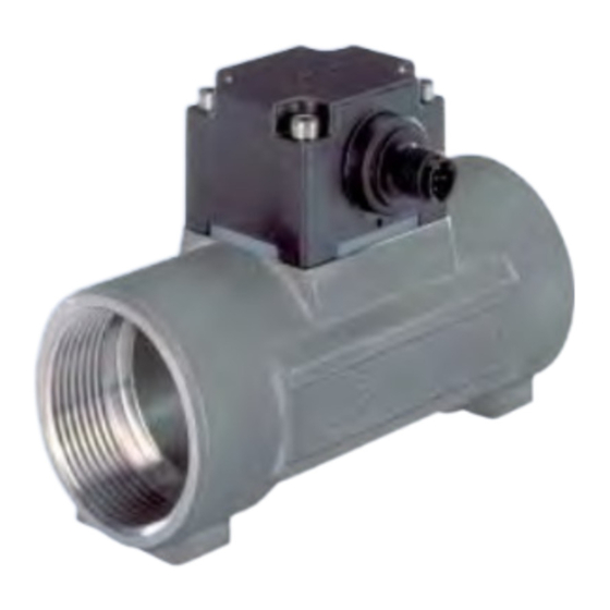
5.2.1. Aufbau 4.3. Informationen im Internet Der Sensor 8012 besteht aus einem Elektronikmodul SE12 mit integ- Bedienungsanleitungen und Datenblätter zum Typ 8012 finden Sie riertem Flügelrad und einem Fitting S012 zur Montage des Geräts an im Internet unter: jeder Art von Rohrleitung mit DN6 bis DN65.
Typ 8012 Beschreibung • Eine rote Signalleuchte signalisiert Fehlfunktionen des Sensors Q = f/K (siehe Kap. 10.4.1 ). Je nach bestellter Version besitzt der Pulsausgang die folgenden Der elektrische Anschluss erfolgt je nach Version über ein Kabel mit einer Eigenschaften: Länge von 1 m oder über einen orientierbaren M12-Steckverbinder.
Typ 8012 Beschreibung 5.2.3. Version mit Pulsausgang und Je nach bestellter Version besitzt der Stromausgang die folgenden Eigenschaften: Stromausgang Pulsausgang Eigenschaften Mögliche Konfigurationen (auf Strom- des Stromaus- Anfrage) ausgang der Die Eigenschaften des Pulsausgangs sind mit den Eigenschaften gangs Basisversionen einer Version identisch, die nur einen Pulsausgang besitzt.
Typ 8012 Beschreibung 5.3. Beschreibung des Typenschilds des 8012 5.4. Beschreibung des Typenschilds des SE12 Messgröße und Sensortyp Messgröße und Sensortyp Nenndurchmesser des Fittings: Nenndurchmesser des Fittings: entweder DN6 oder DN8 (DN-Angabe <15), entweder DN6 oder DN8 (DN-Angabe <15), oder DN15 bis 65 (DN-Angabe >=15) oder DN15 bis 65 (DN-Angabe >=15)
Typ 8012 Technische Daten TECHNISCHE DATEN Art der Flüssigkeit Voraussetzungen Flüssigkeitsgruppe 1 nur DN ≤ 25 6.1. Betriebsbedingungen Kap. 1.3.a DN ≤ 32 Flüssigkeitsgruppe 2 Umgebungstemperatur: -15 °C bis +60 °C (Betrieb und Lagerung) oder DN > 32 und PNxDN ≤ 1000 Kap.
Typ 8012 Technische Daten 6.3. Allgemeine technische Daten Kabel (verseilt) 6.3.1. Mechanische Daten Element Werkstoff Elektronikgehäuse SE12 Stopfbuchse, M12- Steckverbinder Kabel, 1 m PVC, T° max = 80 °C Dichtung in Kontakt mit der FKM als Standard Flüssigkeit (EDPM als Option)
Seite 64
NPT 2 24.0 24.0 Bild 3: Abmessungen des 8012 mit Fitting mit G, Rc oder NPT Außengewinde aus Edelstahl, Messing, PVC oder PVDF Bild 2: Abmessungen des 8012 mit Fitting mit G, Rc oder NPT G, NPT oder Rc je nach Fitting-Version...
Seite 65
Typ 8012 Technische Daten DN [mm] P [mm] A [mm] D [Zoll] 55.0 Rd40 x 1/6" 58.8 Rd60 x 1/6" 62.6 Rd70 x 1/6" Bild 4: Abmessungen des Fittings 8012 mit Außengewinde nach SMS 1145 aus Edelstahl deutsch...
Seite 66
102.0 125.0 165.0 68.7 230.0 ANSI 41.0 4x19.0 92.1 120.6 152.0 68.7 267.0 41.0 4x19.0 96.0 120.0 155.0 Bild 5: Abmessungen des 8012 mit Fitting mit Flansch nach EN 1092-1 (ISO PN16), ANSI B16-5-1988 und JIS 10K aus Edelstahl deutsch...
Seite 67
58.8 119.0 EN ISO 1127 / 42.40 2.00 ISO 4200 SMS 3008 Bild 6: Abmessungen des 8012 mit Fitting mit Schweißenden 55.2 104.0 ASME BPE 32.00 1.65 nach EN ISO 1127 / ISO 4200, SMS 3008, BS 4825/ 55.2 104.0 DIN 11850 Reihe2 35.00...
Seite 68
Typ 8012 Technische Daten 58.8 180.0 ISO (Rohrleitung EN 38.4 43.5 50.5 Norm ISO 1127 / ISO 4200) [mm] [mm] [mm] [mm] [mm] [mm] ISO (Rohrleitung EN SMS 3017 ISO 2852 ISO 1127 / ISO 4200) ASME BPE SMS 3017 ISO 2852...
Seite 69
Typ 8012 Technische Daten Bild 7: Abmessungen des 8012 mit Fitting Clamp nach ISO (für Rohrleitungen nach EN ISO 1127 / ISO 4200), SMS 3017/ISO 2852 , BS 4825 / ASME BPE DIN 32676 aus Edelstahl Verfügbar mit Innenrauigkeit Ra = 0,8 µm...
Seite 70
60.3 60.80 Bild 8: Abmessungen des 8012 mit Überwurfmutter mit Klebe- oder Schweißmuffen nach DIN 8063, ASTM D 1785/76 und JIS K aus PVC, nach DIN 16962 aus PP oder nach ISO 10931 aus PVDF * Ausschließlich aus PVC A [mm]...
Typ 8012 Technische Daten 6.3.2. Allgemeine Daten Durchmesser der Leitungen DN6 bis DN65, je nach Finition: (der passende Durchmesser wird mit den Durchfluss/DN/Fließgeschwindigkeit-Rechnern in Kap. 7.3 bestimmt). Verfügbare DN Finition Werkstoff Innengewinde Edelstahl Messing Außengewinde Edelstahl nach SMS 1145 Andere Schweißenden...
Seite 72
Typ 8012 Technische Daten max. Fehler [%] Art der Flüssigkeit Infrarotdurchlässig (optischer Sensor) Max. Flüssigkeits- Fitting aus Edelstahl, Messing, PVDF: a) 100 °C, Umgebungstemperatur ≤ = 45° temperatur Typische Bürkert b) 90 °C, wenn Umgebungstemperatur zwi- Kurve schen 45 °C und 60 °C Fitting aus PP: 80 °C...
Typ 8012 Technische Daten 6.3.3. Elektrische Daten 4-20 mA, standardmäßig Senke-Modus, Stromausgang (je nach entspricht der Rotationsfrequenz des Flü- Version) Stromversorgung 12-36 VDC, gefiltert und geregelt gelrads (standardmäßig). Programmierbar auf Anfrage. max. 60 mA Verbrauch Ω bei 36 VDC •...
Typ 8012 Technische Daten 6.3.5. K-Faktoren Die K-Faktoren wurden alle unter den folgenden Referenzbedingungen bestimmt: Flüssigkeit = Wasser, Wasser- und Umgebungstemperatur von 20 °C, Berücksichtigung der Mindestein- und -auslaufstrecken, angepasste Rohrleitungsabmessungen. K-Faktoren Werkstoff Anschlusstyp und Norm DN15 DN20 DN25 DN32...
Typ 8012 Installation und Verkabelung INSTALLATION UND WARNUNG! VERKABELUNG Verletzungsgefahr bei unsachgemäßer Installation! 7.1. Sicherheitshinweise • Fluidische und elektrische Installationen dürfen nur durch autori- siertes Fachpersonal und mit geeignetem Werkzeug durchgeführt werden! GEFAHR! • Verwenden Sie unbedingt geeignete Sicherheitsvorrichtun- Verletzungsgefahr durch hohen Druck in der Anlage! gen (ordnungsgemäß...
Empfehlungen für die Installation des 8012 an der Rohrleitung Bild 11: Kurven der Temperatur-Druck-Abhängigkeit der Flüssigkeit Bei der Installation eines 8012 mit optischem Sensor: • Das Gerät vor starken Lichtintensitäten schützen, um jede Störung der Messwerte zu vermeiden. • Darauf achten, dass der Pfeil an der Gehäuseseite in Flussrichtung der Flüssigkeit zeigt.
Seite 77
Typ 8012 Installation und Verkabelung → → Das Gerät so an der Rohrleitung installieren, dass die Min- Falls erforderlich, einen Strömungsberuhiger verwenden, um die desteinlauf- und -auslaufstrecken eingehalten werden, wie in Messgenauigkeit zu verbessern. Bild 12 und Norm EN ISO 5167-1 dargestellt.
Typ 8012 Installation und Verkabelung 7.2.2. Installation eines Sensors mit Fitting mit Schweißenden Richtig Falsch HINWEIS Das Elektronikmodul SE12 und die Dichtung können während Flussrichtung des Anschweißen des Fittings an die Leitung beschädigt sein. • Vor dem Anschweißen an die Leitung die 4 Befestigungsschrauben des Elektronikmoduls SE12 lösen.
Typ 8012 Installation und Verkabelung • Kontrollieren Sie, ob die Dichtungen unversehrt sind. • Setzen Sie je nach dem Prozess (in Temperatur und Flüssigkeitsart) geeignete Dichtungen in die Rillen des Clamp-Fittings ein. → Das Clamp-Fitting mittels einer Rohrschelle an die Leitung befestigen.
Typ 8012 Installation und Verkabelung 7.3. Rechner Diese Rechner ermöglichen die Bestimmung des für die Anwendung je nach Fließgeschwindigkeit und Durchfluss geeigneten DN für Rohrleitung und Fitting. deutsch...
Typ 8012 Installation und Verkabelung 7.4. Elektrische Leitungen Den Potentialausgleich der Installation gewährleisten (Stromversorgung - 8012): GEFAHR! • Die verschiedenen Erdungskabel der Anlage miteinander Verletzungsgefahr durch Stromschlag! verbinden, um die Potentialunterschiede auszugleichen, die sich zwischen zwei Erdungspunkten bilden können. •...
Typ 8012 Installation und Verkabelung 7.4.1. Bauen Sie die Buchse zusammen Pin des Kabels der M12-Buchse, die als Farbe des (Bestell-Nr 917116) Option erhältlich ist (Bestellnr. 438680) Leiters braun → Schrauben Sie die Mutter weiß blau [1] vollständig ab. schwarz →...
Typ 8012 Installation und Verkabelung Eingang Stromversorgung Stromversorgung 4-20 mA braun blau grau schwarz blau weiß grau Last braun Bild 19: Anschluss eines Pulsausgangs im PNP-Modus Bild 21: Anschluss eines Stromausgangs im Quelle-Modus Funktionserde; Wenn eine direkte Erdung nicht möglich ist, einen Konden-...
Seite 84
Typ 8012 Installation und Verkabelung Stromversorgung Eingang Stromversorgung 4-20 mA braun weiß grün grau Bild 24: Anschluss des Stromausgangs im Senke-Modus Last (Standard) einer Version mit Kabel Bild 22: Anschluss des Pulsausgangs im NPN-Modus (Standard) Stromversorgung einer Version mit Kabel.
Typ 8012 Inbetriebnahme BEDIENUNG UND FUNKTION INBETRIEBNAHME 9.1. Sicherheitshinweise 8.1. Sicherheitshinweise WARNUNG! WARNUNG! Verletzungsgefahr bei unsachgemäßer Bedienung! Verletzungsgefahr bei unsachgemäßer Inbetriebnahme! Nicht sachgemäßer Betrieb kann zu Verletzungen sowie Schäden Nicht sachgemäße Bedienung kann zu Verletzungen, sowie am Gerät und seiner Umgebung führen.
9.2.2. Schaltfunktion Kontakt Nicht invertiert Kontakt Invertiert Der Pulsausgang des 8012 kann zum Umschalten eines Magnetventils oder zum Aktivieren eines Alarms programmiert werden. Die folgenden Parameter können vorprogrammiert werden: • Die Schaltweise: Hysterese oder Fenster, invertiert oder nicht untere untere...
Pulsausgang, nicht invertiert und invertiert Flussrichtungsumkehr (nur 8012 mit optischem Sensor) Bei einem 8012 mit optischem Sensor kann der Pulsausgang so vor- programmiert werden, dass die Flussrichtungsumkehr der Flüssigkeit angezeigt wird. Die Anzeige der Flussrichtungsumkehr kann sofort oder verzögert erfolgen. Das Verhalten des Ausgangs hängt von der Anschlussweise ab (NPN oder PNP), außerdem vom Umschaltmodus...
Seite 88
Invertiert Nicht invertiert Nicht invertiert Verz. = 2 s Verz. = 2 s Invertiert Invertiert NPN-Pulsausgang PNP-Pulsausgang Bild 32: Beispiele für das Verhalten des 8012 in Abhängigkeit vom Durchfluss in der Leitung und der für den Pulsausgang gewählten Schaltweise deutsch...
• ein erweiterter Ausgangsbereich oder der Stromausgangsbereich spezifische Einheit umgewandelt wird. entsprechend einem Durchflussbereich In diesem Fall wird der 8012 mit dem K-Faktor Ihres Geräts und der • eine andere Dämpfung der Stromschwankungen als bei den gewünschten Durchflusseinheit vorprogrammiert. Basisversionen.
Typ 8012 Wartung, Fehlerhabung 9.3.3. Dämpfung der WARTUNG, FEHLERHABUNG Stromschwankungen Wenn der Durchfluss schnell variiert, kann das Signal des Stromaus- 10.1. Sicherheitshinweise gangs Ihres Geräts stabilisiert werden. GEFAHR! Das Gerät kann mit einer der 10 verfügbaren Filterebenen vorpro- grammiert werden, die von keiner Filterung bis zu maximaler Filterung Verletzungsgefahr durch hohen Druck in der Anlage! reichen.
10.2. Wartung und Reinigung Je nach Art der Flüssigkeit regelmäßig die Schmutzansammlungen am Flügelrad überprüfen. Bild 36: Explosionszeichnung des 8012 → HINWEIS! Die 4 Schrauben des Elektronikmoduls lösen und dieses vom Fitting abnehmen. Das Gerät kann durch Reinigungsmittel beschädigt werden.
Typ 8012 Wartung, Fehlerhabung 10.4. Problemlösung 10.4.1. Durch die Signalleuchten angezeigte Probleme GEFAHR! Zustand Zustand Zustand Mögliche Verletzungsgefahr durch hohen Druck in der Anlage! rote grüne Strom- Was tun? Ursache Leuchte Leuchte ausgang • Vor dem Lösen der Anschlüsse die Flüssigkeitszirkulation stoppen...
Typ 8012 Wartung, Fehlerhabung 10.4.2. Nicht durch die Signalleuchten ERSATZTEILE, ZUBEHÖR angezeigte Probleme VORSICHT Siehe Problem Was tun? Verletzungsgefahr, Sachschäden durch ungeeignete Teile! Kapitel Der Sensor arbeitet • Verkabelung überprüfen Falsches Zubehör und ungeeignete Ersatzteile können Ver- nicht letzungen und Schäden am Gerät und dessen Umgebung •...
Typ 8012 Wartung, Fehlerhabung VERPACKUNG, TRANSPORT ENTSORGUNG → Entsorgen Sie das Gerät und die Verpackung umweltgerecht. VORSICHT! Transportschäden! VORSICHT! Ein unzureichend geschütztes Gerät kann durch den Transport Umweltschäden durch Teile, die durch Flüssigkeiten kontami- beschädigt werden. niert wurden! • Transportieren Sie das Gerät vor Nässe und Schmutz geschützt •...
Seite 97
5.2.1. Construction ................9 7.2.1. Recommandations d'installation du 8012 sur la 5.2.2. Version avec sortie impulsion .......... 10 conduite ................28 5.2.3. Version avec sortie impulsion et sortie courant ... 11 7.2.2. Installation d'un capteur 8012 avec raccord à em- français...
Seite 98
Fréquence proportionnelle à un volume ......37 9.2.2. Fonction commutation ............38 9.2.3. Détection du changement de sens de circulation du fluide (8012 avec capteur optique uniquement) ... 39 9.3. Sortie courant ................... 41 9.3.1. Extension de la plage de courant ........41...
Type 8012 A propos de ce manuel A PROPOS DE CE MANUEL ATTENTION Ce manuel décrit le cycle de vie complet de l'appareil. Conservez-le Met en garde contre un risque éventuel. de sorte qu'il soit accessible à tout utilisateur et à disposition de tout •...
• Ne pas utiliser cet appareil en atmosphère explosible. • Le contrôleur de débit 8012 est exclusivement destiné à la mesure du débit dans des liquides. • Ne pas utiliser cet appareil pour la mesure de débit de gaz.
Type 8012 Consignes de sécurité de base CO NS IG NE S DE SÉ C UR IT É DE BA S E Situations dangereuses diverses Ces consignes de sécurité ne tiennent pas compte : Pour éviter toute blessure, veiller à : •...
• Veiller également à ne pas toucher les composants électriques pages de ce manuel. sous tension. Elles sont également disponibles sur internet sous : L'appareil type 8012 a été développé en intégrant les règles www.burkert.com Bürkert Entreprise Sites de sécurité reconnues et est conforme à l'état de la technique.
La société Bürkert n'est aucunement responsable d'une quel- conque perte ou détérioration liée au produit, au service, à cette Le capteur de débit 8012 avec capteur magnétique est destiné à la garantie ou autre, y compris des pertes financières ou intan- mesure du débit de liquides neutres ou légèrement agressifs et exempts...
Type 8012 Description Le raccordement électrique s‘effectue, selon la version, via un câble Caractéristique de Configurations Sortie impulsion d'une longueur de 1 m ou une embase multibroche M12 orientable. la sortie impulsion possibles (sur sur les versions Le capteur est pourvu, selon la version :...
Type 8012 Description 5.2.3. Version avec sortie impulsion et Selon la version que vous avez commandée, la sortie courant présente les caractéristiques suivantes : sortie courant Caractéris- Configurations possibles (sur Sortie courant Sortie impulsion tique de la demande) sur les ver- Les caractéristiques de la sortie impulsion sont identiques à...
Type 8012 Description 5.3. Description de l'étiquette du 8012 5.4. Description de l'étiquette du SE12 Grandeur mesurée et type de capteur Grandeur mesurée et type de capteur Diamètre Nominal du raccord : Diamètre Nominal du raccord : soit DN6 ou DN8 (indication DN <15), soit DN6 ou DN8 (indication DN <15),...
Type 8012 Description 5.5. Références de commande des versions de base du module SE12 Raccorde- Tension d'ali- Principe de Référence de ment fluidi- Connexion électrique Sorties mentation mesure commande Impulsion, NPN 557054 Embase M12, 5 points Impulsion, NPN + 4-20 mA...
Type 8012 Caractéristiques techniques 6.3. Caractéristiques techniques Câble en toron générales 6.3.1. Caractéristiques mécaniques Elément Matériau Boîtier électronique SE12 Presse-étoupe, embase M12 Câble de 1 m PVC, T° max = 80 °C Joint en contact avec le fluide FKM en standard (EDPM en option) Joint en contact avec l'air ambiant EDPM Fig.
Seite 110
NPT 2 24.0 24.0 Fig. 3 : Dimensions du 8012 avec raccord à embouts filetés G, Rc, NPT, en acier inoxydable, laiton, PVC ou PVDF G, NPT ou Rc en fonction de la version du raccord Fig. 2 : Dimensions du 8012 avec raccord à embouts taraudés G, Rc, NPT, en acier inoxydable ou laiton français...
Seite 111
Caractéristiques techniques DN [mm] P [mm] A [mm] D [pouce] 55.0 Rd40 x 1/6" 58.8 Rd60 x 1/6" 62.6 Rd70 x 1/6" Fig. 4 : Dimensions du 8012 avec raccord à embouts filetés selon SMS 1145, en acier inoxydable français...
Seite 112
165.0 68.7 230.0 ANSI 41.0 4x19.0 92.1 120.6 152.0 68.7 267.0 41.0 4x19.0 96.0 120.0 155.0 Fig. 5 : Dimensions du 8012 avec raccord à brides selon EN 1092-1 (ISO PN16), ANSI B16-5-1988 et JIS 10K, en acier inoxydable français...
Seite 113
119.0 EN ISO 1127 / 42.40 2.00 ISO 4200 SMS 3008 Fig. 6 : Dimensions du 8012 avec raccord à embouts à souder 55.2 104.0 ASME BPE 32.00 1.65 selon EN ISO 1127 / ISO 4200, SMS 3008, BS 4825/ ASME BPE et DIN 11850 Série 2, en acier inoxydable...
Seite 114
Type 8012 Caractéristiques techniques 58.8 180.0 ISO (conduite EN ISO 38.4 43.5 50.5 Norme 1127 / ISO 4200) [mm] [mm] [mm] [mm] [mm] [mm] ISO (conduite EN ISO SMS 3017 ISO 2852 1127 / ISO 4200) ASME BPE SMS 3017 ISO 2852...
Seite 115
Type 8012 Caractéristiques techniques Fig. 7 : Dimensions du 8012 avec raccord Clamp selon ISO (pour conduites EN ISO 1127 / ISO 4200), SMS 3017 / ISO 2852 1), BS 4825 / ASME BPE 1) et DIN 32676, en acier inoxydable Disponibles avec une rugosité...
Seite 116
60.3 60.80 Fig. 8 : Dimensions du 8012 avec raccord union à souder ou à coller selon DIN 8063, ASTM D 1785/76 et JIS K en PVC, DIN 16962 en PP ou ISO 10931 en PVDF * Uniquement en PVC...
Type 8012 Caractéristiques techniques 6.3.2. Caractéristiques générales Diamètre des conduites DN6 à DN65, en fonction de la finition : (le diamètre adéquat étant déterminé grâce aux abaques débit/DN/vitesse du fluide au parag. 7.3 ). DN disponibles Finition Matériau Embouts taraudés...
Seite 118
Type 8012 Caractéristiques techniques Type de fluide transparent aux infra-rouges Erreur max. [%] (capteur optique) Température max. Raccord en acier inoxydable, laiton, PVDF : a) 100 °C si la température ambiante ≤ +45 °C du fluide b) 90 °C si la température ambiante est com- Courbe typique prise entre 45 °C et 60 °C...
Type 8012 Caractéristiques techniques 6.3.3. Caractéristiques électriques 6.3.4. Raccordements électriques Alimentation 12-36 VDC, filtrée et régulée Version Type Avec câble câble de 1 m. max. 60 mA Consommation Avec embase embase M12 mâle, 5 pôles, orientable (à 12 VDC pour la version avec sortie...
Type 8012 Caractéristiques techniques 6.3.5. Facteurs K Les facteurs K ont tous été déterminés dans les conditions de ré fé ren ce suivantes : fluide = eau, températures de l’eau et ambiante de 20 °C, distances amont et aval minimales respectées, dimensions des conduites adaptées.
Type 8012 Installation et câblage INSTALLATION ET CÂBLAGE AVERTISSEMENT Risque de blessure dû à une installation non conforme. 7.1. Consignes de sécurité • L'installation électrique et fluidique ne peut être effectuée que par DANGER du personnel habilité et qualifié, disposant des outils appropriés.
7.2.1. Recommandations d'installation du 8012 sur la conduite A : plage d’utilisation du capteur complet Lors de l'installation d'un 8012 avec capteur optique : Fig. 11 : Courbes de dépendance température - pression du • Protéger l'appareil de fortes intensités lumineuses pour fluide éviter toute perturbation des mesures.
Seite 123
Type 8012 Installation et câblage → → Installer l'appareil sur la conduite de sorte que les distances Utiliser si nécessaire un tranquiliseur de circulation pour amélio- amont et aval soient respectées, selon la Fig. 12 et la norme rer la précision des mesures.
Type 8012 Installation et câblage 7.2.2. Installation d'un capteur 8012 avec raccord à embouts à souder Correct In cor rect REMARQUE Le module électronique SE12 et le joint d'étanchéité peuvent Sens de circulation être endommagés lors du soudage du raccord sur la canali- du fluide sation.
Type 8012 Installation et câblage → Fixer le raccord Clamp sur la canalisation à l'aide d'un collier de serrage. 7.2.4. Installation d'un capteur avec raccord à brides → Respecter les recommandations d'installation décrites au § 7.2.1 • Vérifier le bon état des joints.
Type 8012 Installation et câblage 7.3. Abaques Ces abaques permettent de déterminer le DN de la conduite et du raccord approprié à l'application, en fonction de la vitesse du fluide et du débit. français...
Si une pose contiguë est inévitable, respecter une distance minimale de 30 cm. 8012 avec câble 8012 avec embase M12 *) Si une mise à la terre directe est impossible, brancher un condensateur de 100 nF / 50 V entre la borne négative de l'alimentation et la terre **) Si votre câble est blindé.
Type 8012 Installation et câblage 7.4.1. Assembler le connecteur femelle Broche du câble M12 femelle disponible en Couleur du (réf. de commande 917116) option (réf. de commande 438680) conducteur brun → Desserrer complètement blanc bleu l‘écrou [1] → noir Enlever la partie arrière du gris connecteur [2].
Type 8012 Installation et câblage Alimentation Alimentation Entrée 4-20mA bleu gris brun noir bleu blanc gris Charge brun Fig. 19 : Raccordement sortie impulsion en mode PNP d'une Fig. 21 : Raccordement sortie courant en mode source d'une version avec embase M12 version avec embase M12 Terre fonctionnelle ;...
Seite 130
Type 8012 Installation et câblage Alimentation Alimentation Entrée 4-20mA brun blanc vert gris Fig. 24 : Raccordement de la sortie courant en mode puits (par défaut) d'une version avec câble Charge Terre fonctionnelle ; Si une mise à la terre directe est impossible, brancher un condensateur de 100 nF / 50 V entre la borne négative de l'alimentation...
Type 8012 Mise en service RÉGLAGE ET MISE EN SERVICE FONCTIONNALITÉS 8.1. Consignes de sécurité 9.1. Consignes de sécurité AVERTISSEMENT AVERTISSEMENT Risque de blessure dû à une mise en service non conforme. La mise en service non conforme peut entraîner des blessures et Risque de blessure dû...
Contact Non inversé Contact Inversé La sortie impulsion de votre 8012 peut être programmée pour com- muter une électrovanne ou activer une alarme. Les paramètres suivants peuvent être pré-programmés : • le mode de commutation : hystérésis ou fenêtre, inversé ou non •...
(8012 avec capteur optique uniquement) Sur un 8012 avec capteur optique, la sortie impulsion peut être pré-pro- grammée pour indiquer le changement de sens de circulation du fluide. L'indication du changement de sens peut être immédiate ou temporisée.
Seite 134
Tempo. = 2s Inversé Inversé Sortie impulsion PNP Sortie impulsion NPN Fig. 32 : Exemples de comportement du 8012 en fonction du débit dans la conduite et du mode de com mu ta tion choisi pour la sortie impulsion français...
à votre application. • une plage de sortie étendue ou la plage de sortie courant corres- Dans ce cas, le 8012 est préprogrammé avec le facteur K de votre pondant à une plage de débit appareil et l'unité de débit souhaitée.
Type 8012 Maintenance et depannage 9.3.3. Atténuation des variations de MAINTENANCE ET courant DEPANNAGE Lorsque le débit varie rapidement, le signal de sortie courant de votre appareil peut être stabilisé. 10.1. Consignes de sécurité Votre appareil peut être pré-programmé avec l'un des 10 niveaux de filtrage disponibles, variant de aucun filtrage à...
En fonction de la nature du fluide, vérifier régulièrement l'encrasse- ment de l'ailette. Fig. 36 : Vue éclatée du 8012 REMARQUE → Desserrer les 4 vis du module électronique et le retirer du rac- L'appareil peut être endommagé par le produit de nettoyage.
Type 8012 Maintenance et depannage 10.4. En cas de problème 10.4.1. Problèmes signalés par les voyants DANGER Etat Etat Etat Cause pos- Risque de blessure dû à la présence de pression élevée dans voyant voyant sortie Que faire ? sible l'installation.
Type 8012 Maintenance et depannage 10.4.2. Problèmes non signalés par les PIÈCES DE RECHANGE ET voyants ACCESSOIRES Voir para- ATTENTION Problème Que faire ? graphe Le capteur ne fonc- • Vérifier le câblage Risque de blessure et de dommage matériel dus à l'utilisation tionne pas •...
Seite 140
Type 8012 Maintenance et depannage Pièce de rechange Référence de commande FKM - DN40 431559 FKM - DN50 431560 EPDM - DN8 448680 EPDM - DN15 431561 EPDM - DN20 431562 EPDM - DN25 431563 Fig. 37 : Joint pour raccord en métal...
Type 8012 Emballage et transport EMBALLAGE ET TRANSPORT ELIMINATION DU PRODUIT → Eliminer l'appareil et l'emballage dans le respect de l'environne- ATTENTION ment. Dommages dûs au transport ATTENTION Le transport peut endommager un appareil insuffisamment pro- tégé. Dommages à l'environnement causés par des pièces contami- •...
Seite 146
Addresses of Burkert locations / Adressliste Bürkert Standorte Europe/Europa AustriA, Österreich FrAnCe, Frankreich polAnD, polen Bürkert-Contromatic G.m.b.H. Burkert Contromatic SAS Burkert-Contromatic GmbH Diefenbachgasse 1-3 Rue du Giessen Oddzial w Polsce A-1150 Wien F-67220 Triembach au Val Bernardynska street 14 a Phone: +43 (0)1-894 13 33 Phone: +33 (0)388-58 91 11 PL-02-904 Warszawa...
Seite 147
Addresses of Burkert locations / Adressliste Bürkert Standorte Europe/Europa uniteD kingDom, Vereinigtes kÖnigreich Burkert Contromatic Limited Brimscombe Port Business Park Brimscombe, Stroud Glos, GL5 2QQ / UNITED KINGDOM Phone: +44 (0)1453-731 353 Fax: +44 (0)1453-731 343 E-mail: sales.uk@burkert.com Addresses of Burkert locations / Adressliste Bürkert Standorte Asia Pacific/Asien Pazifik AustrAliA, australien south australia...
Seite 148
Addresses of Burkert locations / Adressliste Bürkert Standorte Asia Pacific/Asien Pazifik shanghai JApAn, Japan new zeAlAnD, neuseelanD Burkert Contromatic (Shanghai), Co., Ltd. Burkert Ltd. BURKERT CONTROMATIC NEW ZEALAND LTD Room 501/502 Xin Gai Nian Mansion, Imasu moto asakusa-building 44 Rennie Drive No.
Seite 149
Addresses of Burkert locations / Adressliste Bürkert Standorte Africa/Afrika AFriCA, aFrika Bürkert Contromatic (Proprietary) Ltd. 233 Albert Amon Road Millennium Business Park Meadowdale, Germiston (Postal: P.O. Box 26260, East Rand 1462) SOUTH AFRICA Phone: +27 (0)11-574 60 00 Fax: +27 (0)11-454 14 77 E-mail: sales.za@burkert.com Addresses of Burkert locations / Adressliste Bürkert Standorte...
Seite 150
Addresses of Burkert locations / Adressliste Bürkert Standorte Germany/Deutschland EADQUARTER AND SERVICE CENTER STAMMSITZ UND SERVICE-CENTER DISTRIBUTION CENTER / VERTRIEBS-CENTER Ingelfingen Berlin Hannover Bürkert GmbH & Co. KG Bürkert GmbH & Co. KG Bürkert GmbH & Co. KG Fluid Control Systems Fluid Control Systems Fluid Control Systems Christian-Bürkert-Straße 13 - 17...