EN 100 015-1. Always protect the device from electromagnetic perturbations, and when installed outside, protect it from the rain and ultraviolet radiations. Manufacturer’s address Bürkert & Cie Rue du Giessen 67220 TRIEMBACH-au-VAL FRANCE 8041...
1.4 CONVERSION OF THE FLOW VELOCITY INTO A FLOW RATE - FACTOR K The 8041 measures the flow velocity (in m/s) of the medium and converts it into a current (in mA) and a frequency rating (in Hz). The current I or the frequency f are proportional to the flow rate Q (l/s); The proportionality factor is called “factor K”:...
Seite 5
INTRODUCTION Example Be a 8041 inserted into an S020, with DN50 and made of stainless steel: = 11,24 fitting The selected full scale is 5 m/s. The factor K to be used for the conversion of the output frequency f into a flow rate Q is:...
This Quick Start diagram shows the different installation and programming steps to be carried out to ensure the good operation of the appliance. Unpack the appliance Contact your Order Burkert agent code OK? Unscrew the 4 screws See 3.2 Select the mains frequency by means of switch 1 Select the filtering level by See 3.3...
Seite 7
See 3.6 Program the relay output See 5.1, Error See 3.1 Check that the green led flashes once signalling Replace the cover in the proper orientation (see photo) and screw the 4 screws The appliance is ready for use 8041...
CONFIGURATION 3.1 GENERAL COMMENTS The 8041 magmeter has 2 operating modes: - the Readout mode: to visualize the measured flow velocity and the values programmed for the relay operation. - the Configuration mode: to calibrate the device (“zero flow” point and measuring full scale) and program the relay parameters.
* The device automatically goes back to the reading mode of the flow velocity measurement, if the push-button is not pressed for 10 s. Green led blinking Bargraph ..1 up to 5 times Led off Led lit Red led off Push-button Red led lit Led blinking 8041...
50 Hz 60 Hz 3.3 FILTERING LEVEL Filtering allows the attenuation of fluctuations in the flow. The 8041 sensor can work without or with filtering. Switch 2 makes it possible to activate or inhibit filtering : Flow filtering activation...
- Press and hold the push-button: after 2 seconds, the red led lights up (Configuration mode) and the bargraph shows the features “zero flow point 1 2 3 4 5 6 7 8 9 10 calibration” and “full scale calibration” alternately. Full scale calibration 8041...
0 to 5 m/s 0 to 10 m/s 0 to full scale (between 2 and 10 m/s) determined by teach-in When selecting a new measuring range, the percentages programmed for the low and high thresholds apply to the new selected full scale. 8041...
The minimal value of the measuring range is 0 m/s. - Set both switches 4 and 5 to ON - Install the 8041 sensor into the pipe (see chapter Installation) - Let the max. flow flow through the pipe - Check whether the green led flashes once and the red led is off (Readout mode).
- The high switching threshold, in a percentage of the full scale - The time-out before switching, from 0 to 100 s. Whether the relay operating is Normally Open or Normally Closed is determined by the connection of the relay to the terminals of the electronic board. 8041...
The switching mode of the relay output can be chosen among 2 modes, either window or hysteresis. - Window mode: the change of state of the relay output (OUT) occurs at any threshold detection: Window mode (NO-wired realy) Window mode (NC-wired relay) Relay output Relay output Low threshold High threshold Low threshold High threshold 8041...
Seite 17
Readout mode. or press and hold the push-button to display another feature. or wait for 10 s to return to the measured flow velocity Readout mode, without validating the displayed feature. 8041...
0-10 m/s measuring the flow velocity Readout mode or wait for 10 s to range, this corresponds to a low return to the flow velocity Readout mode without threshold of 2.4 m/s validating the displayed value. 8041...
Readout mode without 9th Led flashing twice = 2% of the validating the displayed value. full scale The bargraph shows 82% of the full scale, i.e. by a 0-10 m/s measuring range, this corresponds to a high threshold of 8.2 m/s 8041...
Readout mode or wait for 10 s to return to the flow velocity Readout mode without 5 leds lit = 50 sec validating the displayed value. 6th led flashing 2 times = 2 seconds The bargraph shows a time-out of 52 seconds 8041...
- Dismounting precautions: All precautions must be taken before removing the transmitter from the pipe depending on the process used as the pipe may contain dangerous/agressive hot fluids or fluids with high temperatures or pressures. 8041...
It is advisable to mount the transmitter at a 45° angle to 45° the horizontal centre of the pipe as shown in the diagram to avoid having deposits on the electrodes and false measurements due to air bubbles. 45° 8041...
Seite 23
3 x DN 10 x DN Please ensure the pipe design does not allow the build up of air bubbles or cavities within the medium as this will cause measuring errors. Flow direction Flow direction Correct Incorrect Correct Incorrect 8041...
- Use cables with a temperature limit of 105°C minimum. - For normal operating conditions the measuring signal can be transmitted by a shielded cable of 0.75 mm cross section. - The cable must not be installed in combination with carrying lines with a higher voltage or frequency. 8041...
Seite 25
18-36VDC (**) Metallic devices (valve, pump,...) For plastic pipe applications or metallic parts, inserted inside the pipe. (**) If direct earthing is impossible, connect a 100 nF/50 V-condensator between the negative terminal of the power supply and the earth. 8041...
Unscrew the cable gland nut, insert the obstructor and screw the nut back onto the cable gland. Always replace the cover as indicated by the photo opposite ; Screw the 4 screws in an alternating pattern. 8041...
Switch set to 1 2 3 4 5 6 sinking mode 4...20 V+ V- PE Pls+Pls- Connection in sinking mode If direct earthing is impossible, connect a 100 nF/50 V-condensator between the negative terminal of the power supply and the earth. 8041...
INPUT 1 2 3 4 5 6 1 2 3 4 5 6 4...20 V+ V- PE Pls+Pls- 4...20 V+ V- PE Pls+Pls- 8041 8041 Connection to a PLC Connection to a PLC with common - (PNP) with common + (NPN)
Seite 29
INSTALLATION 4.4.3 Connection of the relay output The relay output can operate either in a Normally Open or Normally Closed configuration depending on the wiring to the 8041 electronic board. 18-36 V= Power Supply Normally Open Connection of the relay...
MAINTENANCE 5.2 CLEANING The 8041 sensor may be cleaned with water or a product which is compatible with the materials therein.Your Burkert supplier is available to provide you with any additional information you require. 8041...
Duty cycle = 50% +/-1% - Max current 100 mA (protected against short-circuits and polarity reversals) Current output - Output type Current output from 4 to 20 mA (22 mA for error signalling) - Electrical wiring sourcing or sinking mode 8041...
- Fluids of group 2 according to §1.3b of the directive: PN ≤ 16 bar and DN ≤ 200 It has been designed and manufactured professionally (Article 3.3). The CE mark is not for pressure. The CE mark complies with directives 89/336/EC (EMC) and 73/23/EC (LVD). 8041...
SPECIFICATIONS 6.6 DIMENSIONS 115 mm 88 mm M20 x 1.5 6.7 LABEL DESCRIPTION FLOW:8041-EPDM -IND LONG SST N=10000 18-36V — /220mA 4-20mA REL:230VAC/3A Compact 552780 W41UE Type of magmeter Gasket material Sensor characteristics Serial number Version of the magmeter Relay data...
DN 06 0.05 0.05 0.01 0.005 0.02 0.01 0.3 0.5 Flow velocity Selection example: Nominal flow rate = 10 m Ideal flow velocity = 2-3 m/s => As defined by the flow chart the required fitting diameter is DN40. 8041...
Seite 37
DN25 DN20 DN15 DN08 DN06 0.05 0.02 0.01 0.3 0.5 Flow velocity Selection example: Nominal flow rate = 50 gpm Ideal flow velocity = 8 fps => As defined by the flow chart the required fitting diameter is 1’’1/2. 8041...
ANNEX 7.3 CONNECTION EXAMPLES Between the 8041 magmeter and the flow transmitter 8025, Low Flow or Batch, in a panel version. On a panel version of the 8025 Low Flow, set SW100 to position 2 and SW101 to position 3.
Seite 39
ANNEX Between the 8041 magmeter and the positioner 1067 mounted on a diaphragm valve 2031 24 V= 24 VDC +24 V 4-20 mA I/O4 I/O3 1 2 3 4 5 6 I/O2 I/O1 4...20 V+ V- PE Pls+ Pls- 1067...
Seite 42
Conformité aux normes..................33 Dimensions ......................34 Description de l‘étiquette ..................34 ANNEXES ........................35 Références de commande ...................35 7.1.1 Produits finis..........................35 7.1.2 Accessoires et pièces de rechange................35 Diagrammes Débit - vitesse - DN du raccord ..........36 Exemples de raccordement .................38 8041...
EN 100 015-1. Protéger l’appareil contre les perturbations électromagnétiques et, lorsqu’il est installé à l’extérieur, de la pluie et des rayons ultraviolets. Adresse du fabricant Bürkert & Cie Rue du Giessen 67220 TRIEMBACH-au-VAL FRANCE 8041...
1.4 RELATION ENTRE LA VITESSE ET LE DÉBIT DU FLUIDE - FACTEUR K Le 8041 mesure la vitesse du fluide (en m/s) et la convertit en un courant (en mA) et une fréquence (en Hz). Le courant I ou la fréquence f sont proportionnels au débit Q (l/s) ; Le facteur de proportionnalité...
Seite 45
INTRODUCTION Exemple Soit un 8041 inséré dans un raccord S020 de DN50 en acier inoxydable : = 11,24 raccord La plage de mesure sélectionnée est 0 à 5 m/s. Le facteur K à utiliser pour la conversion de la fréquence de sortie f en débit Q est :...
Ce Quick Start permet d’installer et de programmer rapidement le débitmètre. Déballer l'appareil Réf. de Contacter le commande revendeur Burkert Dévisser les 4 vis Sélectionner la fréquence délivrée par le réseau Voir 3.2 électrique, à l'aide de l'interrupteur 1 Sélectionner le niveau de filtrage Voir 3.3...
Seite 47
Programmer les paramètres de la sortie relais Voir 5.1, Indication Voir 3.1 Vérifier que la led verte clignote une fois d’erreur Replacer le couvercle en respectant le sens de montage (voir photo ci-contre) et visser les 4 vis L'appareil est prêt à l'emploi 8041...
CONFIGURATION 3.1 GÉNÉRALITÉS Le débitmètre 8041 a 2 modes de fonctionnement : - le mode Lecture. Ce mode permet de visualiser la vitesse du fluide mesurée par le capteur et les valeurs programmées pour le fonctionnement du relais - le mode Configuration. Ce mode permet d’une part de calibrer le débitmètre (point “zéro débit”...
* Si aucun appui de touche n'intervient pendant 10 s, l'appareil revient au mode Lecture de la vitesse mesurée Voyant vert clignotant Bargraphe ..de 1 à 5 fois Led éteinte Led allumée Voyant rouge éteint Bouton-poussoir Voyant rouge allumé Led clignotante 8041...
3.3 NIVEAU DE FILTRAGE Le filtrage permet d’atténuer les fluctuations du débit à l’affichage et sur les sorties courant et fréquence. Le débitmètre 8041 peut fonctionner sans ou avec filtrage. L’interrupteur 2 permet d’activer ou de désactiver le filtrage :...
- Appuyer sur le bouton-poussoir et maintenir l’appui : après 2 secondes, le voyant rouge s’allume (Mode 1 2 3 4 5 6 7 8 9 10 Calibrage) et le bargraphe indique alternativement les fonctions “calibrage zéro débit” et “calibrage pleine Calibrage de la pleine échelle échelle”. 8041...
0 à 10 m/s 0 à pleine échelle calibrée (entre 2 et 10 m/s) Après modification de la plage de mesure, les pourcentages programmés pour les seuils de commutation bas et haut s’appliquent à la nouvelle pleine échelle sélectionnée. 8041...
Pleine échelle + 20% Si aucune des plages de mesure prédéfinies ne convient, Etat du bargraphe le capteur 8041 peut adapter sa pleine échelle à celle de votre application. La valeur minimale de la plage de mesure est 0 m/s.
- la valeur du seuil de commutation haut, en pourcentage de la pleine échelle - le délai avant commutation, de 0 à 100 secondes. Le fonctionnement du relais, Normalement Ouvert (NO) ou Normalement Fermé (NC), est déterminé par câblage du relais sur la carte électronique. 8041...
- En mode fenêtre, le changement d’état de la sortie relais est effectué à chaque détection du seuil haut ou du seuil bas : Mode fenêtre (relais câblé en NO) Mode fenêtre (relais câblé en NC) Sortie relais Sortie relais activée activée désactivée désactivée Seuil bas Seuil haut Seuil bas Seuil haut 8041...
Seite 57
l’appui pour afficher une autre fonction. soit attendre 10 s pour retourner au mode lecture de la vitesse mesurée, sans valider le choix affiché. 8041...
2 leds allumées = 20% de la pleine échelle 3è led clignote 4 fois = 4% de la pleine échelle Le bargraphe indique un seuil bas programmé à 24% de la pleine échelle, c’est-à-dire à 2,4 m/s si la pleine échelle est de 10 m/s. 8041...
échelle 9è led clignote 2 fois = 2% de la pleine échelle Le bargraphe indique un seuil haut programmé à 82% de la pleine échelle, c’est-à-dire à 8,2 m/s si la pleine échelle est de 10 m/s. 8041...
10 s pour retourner au mode lecture de la vitesse mesurée, sans valider la valeur programmée. 5 leds allumées = 50 secondes 6è led clignote 2 fois = 2 secondes Le bargraphe indique une temporisation de 52 secondes. 8041...
- Précautions de démontage : Lors du démontage du débitmètre de la conduite, il faut s’assurer que toutes les précautions dépendant de l’application ont été prises (fluides agressifs, dangereux, température ou pression du fluide élevée...). 8041...
Il est conseillé d’installer le débitmètre avec un angle de 45° par rapport à une horizontale centrée sur la conduite comme 45° schématisé ci-contre, pour éviter les dépôts sur les électrodes et pour que les mesures ne soient pas faussées par d’éventuelles bulles d’air. 45° 8041...
Seite 63
10 x DN S’assurer que la conception de la conduite ne permet pas la formation de bulles d’air ou de cavités dans le fluide pour éviter les erreurs de mesure. Ecoulement du fluide Ecoulement du fluide Correct Incorrect Correct Incorrect 8041...
INSTALLATION 4.2 INSTALLATION Le débitmètre 8041 s’installe sur les conduites à l’aide de nos systèmes de raccordement spéciaux S020. Lors du montage du raccord 4, respecter les consignes décrites au § 4.1. Puis : - Insérer l’écrou 3 sur le raccord 4 et clipser la bague 2 dans la rainure 5.
Seite 65
Dans les applications avec conduite en plastique (*) ou parties métalliques insérées à l’intérieur de la conduite. (**) Si une mise à la terre directe est impossible, brancher un condensateur de 100 nF entre la borne négative de l’alimentation et la terre. 8041...
à l’aide de l’obturateur fourni, afin de garantir l’étanchéité du débitmètre. Dévisser l’écrou du presse-étoupe, insérer l’obturateur puis revisser l’écrou. Le couvercle doit toujours être replacé dans le sens indiqué par la photo ci-contre ; Revisser les 4 vis en croix. 8041...
INSTALLATION 4.4.1 Raccordement de la sortie courant 4-20 mA La sortie courant du 8041 peut être raccordée à un appareil extérieur (API,...) ayant une entrée 4-20 mA en mode source ou en mode puits. Hors tension, veiller à positionner l’interrupteur Puits/Source en fonction du mode choisi.
ENTREE 1 2 3 4 5 6 1 2 3 4 5 6 4...20 V+ V- PE Pls+Pls- 4...20 V+ V- PE Pls+Pls- 8041 8041 Raccordement à un API avec - Raccordement à un API avec + commun (PNP) commun (NPN) Raccordement à...
INSTALLATION 4.4.3 Raccordement de la sortie relais La sortie relais fonctionne soit en mode normalement ouvert (NO) ou normalement fermé (NC) en fonction du raccordement à la carte électronique du 8041. 18-36 V= Alimentation Raccordement du relais en mode 300 mA...
MAINTENANCE 5.2 ENTRETIEN Le débitmètre 8041 peut être nettoyé à l’eau ou avec un produit compatible avec les matériaux qui le composent. Votre fournisseur Burkert reste à votre entière disposition pour tous renseignements complémentaires. 8041...
Rapport cyclique = 50% +/-1% - Courant max. 100 mA (protégé contre les court-circuits et les inversions de polarité) Sortie courant - Type de sortie Courant de 4 à 20 mA (22 mA en cas d’erreur) - Câblage électrique Mode source ou puits 8041...
- Fluides du groupe 2 selon §1.3b de la DESP : PN ≤ 16 bar et DN ≤ 200 Il est conçu et fabriqué conformément aux règles de l’art (Article 3.3). Il ne porte pas de marquage CE pour la DESP. Il porte le marquage CE en accord avec les directives 89/336/CE (CEM) et 73/23/CE (DBT). 8041...
CARACTERISTIQUES TECHNIQUES 6.6 DIMENSIONS 115 mm 88 mm M20 x 1.5 6.7 DESCRIPTION DE L‘ÉTIQUETTE FLOW:8041-EPDM -IND LONG SST N=10000 18-36V — /220mA 4-20mA REL:230VAC/3A Compact 552780 W41UE Type du débitmètre Matériau du joint Caractéristique du capteur Numéro de série Version du débitmètre...
DN 15 DN 08 DN 06 0.05 0.05 0.01 0.005 0.02 0.01 0.3 0.5 Vitesse du fluide Exemple de sélection : Débit nominal = 10 m Vitesse souhaitée = 2-3 m/s => Le diagramme préconise un raccord de DN40. 8041...
Seite 77
DN50 DN40 DN32 DN25 DN20 DN15 DN08 DN06 0.05 0.02 0.01 0.3 0.5 Vitesse du fluide Exemple de sélection : Débit nominal = 50 gpm Vitesse souhaitée = 8 fps => Le diagramme préconise un raccord de 1”1/2 DN40. 8041...
ANNEXE 7.3 EXEMPLES DE RACCORDEMENT Entre le débitmètre 8041 et un transmetteur de débit 8025 Low Flow ou Batch, version encastrable. Sur la version encastrable d’un 8025 Low Flow, placer SW100 sur la position 2 et SW101 sur la position 3.
Seite 79
ANNEXE Entre le débitmètre 8041 et le positionneur 1067 monté sur une vanne à membrane 2031 24 V= 24 VDC +24 V 4-20 mA I/O4 I/O3 1 2 3 4 5 6 I/O2 I/O1 4...20 V+ V- PE Pls+ Pls-...
Anforderungen nach EN 100 015-1 zu beachten. Bei einer Außenanwendung des Sensors schützen Sie das Gerät vom Regen, von Ultraviolettbestrahlung und elektromagnetischen Störungen. Adresse des Herstellers Bürkert & Cie Rue du Giessen 67220 TRIEMBACH-au-VAL FRANKREICH 8041...
1.4 VERHÄLTNIS ZWISCHEN GESCHWINDIGKEIT UND DURCHFLUSS - K FAKTOR Der 8041 misst eine Mediums-Geschwindigkeit (in m/s) und wandelt diese in ein Strom (in mA) und eine Frequenz (in Hz) um. Der K-Faktor beschreibt den linearen Zusammenhang zwischen Ausgangssignal und dem...
EINFÜHRUNG Berechnungs-Beispiel Sei ein 8041 in ein Edelstahl-Fitting S020 von DN50 eingesetzt: = 11,24 Fitting Der ausgewählte Endwert ist 5 m/s. Es ergibt sich folgenden K-Faktor K zur Umwandlung der Ausgangfrequenz f in ein Durchfluss: 200 = 17,79 11,24 Es ergibt sich folgenden K-Faktor K...
QUICK START Dieser Abschnitt bietet eine umfassende Anleitung für Installation und Betrieb des Gerätes, die Ihnen die Inbetriebnahme des Durchflussmessers 8041 erleichtert. Gerät auspacken Wenden Sie sich Nein Bestell-Nr an Ihren Burkert- Zwischenhändler 4 Schrauben losschrauben Siehe 3.2 Wählen Sie die Netzfrequenz mittels des Schalters 1 aus Siehe 3.3...
Seite 87
2 m/s und < 10 m/s auf? Siehe 3.6 Relais-Ausgangsdaten programmieren Siehe 5.1, Siehe 3.1 Nein Überprüfen, ob die grüne Lampe einmal blinkt Fehlermeldung Deckel gemäß Montageausrichtung zurücksetzen (siehe Foto) und 4 Schrauben festschrauben Das Gerät ist betriebsbereit 8041...
Durchflussmessers (Netzfrequenz, Filtertyp der Lampe blinkt 1 mal = 1% Messungen, Messbereich) des Endwerts (oder 1 Sekunde) - Schalter 6: nicht verwendet Setzen Sie immer den Deckel wie im nebenstehenden Foto angezeigt zurück; Schrauben Sie die 4 Schrauben über Kreuz fest. 8041...
Seite 89
* das Gerät kommt automatisch zum Lese-Modus der gemessenen Geschwindigkeit zurück, wenn kein Druck auf den Drucktaster während 10 s entsteht. Bargraph Grüne Anzeige blinkt ..1 bis 5 mal Lampe aus Rote Anzeige aus Lampe leuchtet Drucktaster Rote Anzeige leuchtet Lampe blinkt 8041...
60 Hz 3.3 AUSWAHL DES FILTERTYPS Mit der Filterung können die Durchflussschwankungen auf dem Bragraph und auf den Strom- und Frequenzausgängen abgeschwächt werden. Der Durchflussmesser 8041 kann ohne oder mit Filterung arbeiten. Mit Schalter 2 kann die Filterung aktiviert werden:...
Seite 92
Nullpunktabgleich - Auf den Drucktaster drücken und halten: Nach 2 s leuchtet die rote Anzeige auf (Abgleich-Modus) und der 1 2 3 4 5 6 7 8 9 10 Bargraph zeigt die Funktionen Nullpunktabgleich und Endwert-Kalibrierung wechselnd an. Endwert-Kalibrierung 8041...
0 bis 2 m/s 0 bis 5 m/s 0 bis 10 m/s 0 bis kalibrierter Endwert (zwischen 2 und 10 m/s) Nach Änderung des Messbereichs lassen sich die für die niedrigen und hohen Schaltschwellen programmierten Prozentsätze auf den neu ausgewählten Endwert anwenden. 8041...
Endwert + 20% Bargraphstatus Falls keiner vorbestimmten Messwert für Ihre Applikation geeignet ist, kann der Sensor 8041 mit dem Endwert der Applikation kalibriert werden. Der Minuswert des Messbereichs ist 0 m/s. - Stellen Sie Schalter 4 und 5 auf ON.
- Die niedrige Schaltschwelle, als Prozentsatz des Endwerts - Die obere Schaltschwelle, als Prozentsatz des Endwerts - Die Schaltverzögerungszeit, von 0 bis 100 s. Die Funktionsweise des Relais, entweder stromlos geöffnet (NO) oder stromlos geschlossen (NC) wird durch Anschließen des Relais an die Elektronikplatine bestimmt. 8041...
Zwei Schaltmodi des Relais sind vorhanden: Der Fenster- und der Hysterese-Modus. - Bei dem Fenster-Modus erfolgt die Statusänderung des Relais bei Erkennung jeder Schaltschwelle: Fenster-Modus Fenster-Modus (NO-angeschlossenes Relais) (NC-angeschlossenes Relais) Relais-Ausgang Relais-Ausgang aktiv aktiv inaktiv inaktiv Niedrige Obere Niedrige Obere Schwelle Schwelle Schwelle Schwelle 8041...
Seite 97
Funktion auszuwählen und automatisch zum Lese-Modus der gemessenen Geschwindigkeit zurückzukommen. auf den Drucktaster drücken und halten, um eine andere Funktion auszuwählen. 10 s lang warten, um zum Lese-Modus der gemessenen Geschwindigkeit zurückzukommen, ohne die angezeigte Funktion auszuwählen. 8041...
Endwerts Geschwindigkeit zurückzukommen, ohne den 3te Lampe blinkt 4 mal = 4% des angezeigten Wert zu bestätigen. Endwerts Der Bargraph zeigt einen eingestellten Wert von 24% des Endwerts an, d.h 2,4 m/s bei einem ausgewählten Endwert von 10 m/s. 8041...
Endwerts Geschwindigkeit zurückzukommen, ohne den 9te Lampe blinkt 2 mal = 2% des Endwerts angezeigten Wert zu bestätigen. Der Bargraph zeigt einen eingestellten Wert von 82% des Endwerts an, d.h 8,2 m/s bei einem ausgewählten Endwert von 10 m/s. 8041...
Geschwindigkeit zurückzukommen oder 10 s lang 5 leuchtende Lampen = 50 s warten, um zum Lese-Modus der gemessenen 6te Lampe blinkt 2 mal = 2 s Geschwindigkeit zurückzukommen, ohne den Der Bargraph zeigt eine Verzögerung angezeigten Wert zu bestätigen. von 52 s an. 8041...
4.1.1 Druck-Temperatur-Diagramm Der Sensor und das Fitting, in dem der Sensor installiert ist, arbeiten mit begrenzten Betriebs-Temperaturen und -Drücken. Das folgende Diagramm zeigt die Funktionsbereiche der Einheit aus Sensor 8041 und Fitting für jeden Fitting-Werkstoff: Messing / Edelstahl (PN16) P (Bar)
INSTALLATION 4.1.2 Montagehinweise Der Durchflussmesser 8041 kann auf verschiedene Weise montiert werden, um eine genaue Durchflussmessung zu erhalten; Der Rohrleitungsaufbau sollte jedoch so gestaltet sein, dass das Rohr zu jedem Zeitpunkt vollständig gefüllt ist. Horizontale Montage Richtig Falsch Vertikale Montage...
Seite 103
FS = x,xxx Strömungsrichtung 3 x DN 10 x DN Vergewissern Sie sich bitte, dass der Rohrleitungsaufbau nicht die Bildung von Luftblasen oder -einschlüssen im Medium begünstigt, da diese Messfehler verursachen. Strömungsrichtung Strömungs- richtung Richtig Falsch Strömungsrichtung Richtig Falsch 8041...
INSTALLATION 4.2 INSTALLATION Der Durchflussmesser 8041 kann mit speziell entwickelten Burkert-Fittings S020 einfach in Rohrleitungen installiert werden. Das Fitting muss gemäß den in Abschnitt 4.1 angegebenen Montageanweisungen im Rohr installiert werden. - Die Überwurfmutter 3 auf das Fitting 4 schieben und den Kunststoffring 2 in der Führungsbuchse 5 einrasten lassen.
Seite 105
18-36VDC (**) Metallische Apparate (Ventil, Pumpe,...) Für Kunststoffrohr-Anwendungen (*) oder in die Rohrleitung eingesetzten metallischen Teile (nicht geliefert). (**) Ist keine direkte Erdung möglich, schließen Sie einen 100-nF/50 V-Kondensator zwischen dem negativen Anschluss der Versorgungsquelle und der Erde an. 8041...
Verschluss verstopft werden, um die Dichtheit des Durchflussmessers zu vergewissern. Die Kabelverschraubung aufschrauben dann den Verschluss einschieben und die Kabelverschraubung wieder festschrauben. Setzen Sie immer den Deckel wie im nebenstehenden Foto angezeigt zurück; Schrauben Sie die 4 Schrauben über Kreuz fest. 8041...
INSTALLATION 4.4.1 Verdrahtung des 4-20 mA-Stromausgangs Der Stromausgang des 8041 kann an ein externes Gerät (SPS,...) mit 4-20-mA-Eingang als Quelle oder Senke angeschlossen werden. Stellen Sie den Senke / Quelle-Schalter unter spannungslosem Gerät in Abhängigkeit des Anschlusses richtig ein. 300 mA...
WARTUNG 5.2 PFLEGE Der Durchflussmesser 8041 kann mit Wasser oder einem Reinigungsmittel gereinigt werden, das mit den für den Sensor verwendeten Werkstoffen verträglich ist. Ihre örtliche Burkert-Niederlassung steht Ihnen für alle weitere Auskünfte gern zur Verfügung. 8041...
Frequenz von 0 bis 240 Hz (256 Hz für Fehleranzeige), Taktverhältnis = 50% +/-1% - Zulässiger Strom max. 100 mA (mit Kurzschlussschutz und Schutz gegen Falschpolung) Stromausgang - Ausgangssignal Strom von 4 bis 20 mA (22 mA für Fehleranzeige) - Verkabelung als Quelle oder Senke 8041...
- Flüssigkeitgruppe 2 gemäß §1.3b der Grundnorm: PN ≤ 16 bar und DN ≤ 200 Das Gerät ist kunstgerecht aufgebaut und hergestellt (Artikel 3.3). Das Gerät beträgt keine CE-Marke für unter Druck stehende Produkte. Die CE-Marke gilt für die Grundnormen 89/336/CE (EMV) und 73/23/CE (RNS). 8041...
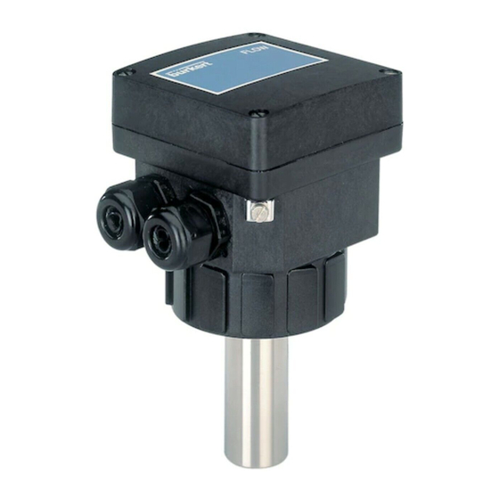
TECHNISCHE DATEN 6.6 ABMESSUNGEN 115 mm 88 mm M20 x 1.5 6.7 BESCHREIBUNG DES TYPENSCHILDS FLOW:8041-EPDM -IND LONG SST N=10000 18-36V — /220mA 4-20mA REL:230VAC/3A Compact 552780 W41UE Typ des Durchflussmessers Werkstoff der Dichtung Sensor-Daten Seriennummer Ausführung des Durchflussmessers Relais-Kenngrößen...
DN 15 DN 08 DN 06 0.05 0.05 0.01 0.005 0.02 0.01 0.3 0.5 Mediums-Geschwindigkeit Auswahlbeispiel: Nominaler Durchfluss = 10 m Ideale Durchflussgeschwindigkeit = 2-3 m/s => Es ergibt sich aus dem Diagramm eine erforderliche Nennweite des Fittings von DN40. 8041...
Seite 117
DN40 DN32 DN25 DN20 DN15 DN08 DN06 0.05 0.02 0.01 0.3 0.5 Mediums-Geschwindigkeit Auswahlbeispiel: Nominaler Durchfluss = 50 gpm Ideale Durchflussgeschwindigkeit = 8 fps => Es ergibt sich aus dem Diagramm eine erforderliche Nennweite des Fittings von 1’’1/2, DN40. 8041...
ANHANG 7.3 ANSCHLUSS-BEISPIELE Zwischen dem Durchflussmesser 8041 und dem getrennten Durchflussmesser 8025 Low Flow oder Batch in der Schaltschrank-Ausführung. Bei der Schaltschrank-Ausführung eines 8025 Low Flow stellen Sie SW100 auf Position 2 und SW101 auf Position 3. 18-30 V= 300 mA 1 2 3 4 5 6 4...20 V+ V- PE Pls+ Pls-...
Seite 119
ANHANG Zwischen dem Durchflussmesser 8041 und dem auf ein Membranventil 2031 montierten Positioner 1067 24 V= 24 VDC +24 V 4-20 mA I/O4 I/O3 1 2 3 4 5 6 I/O2 I/O1 4...20 V+ V- PE Pls+ Pls- 1067 GND2...