Herunterladen Inhalt Inhalt Diese Seite drucken
VOLTCRAFT GM-70 Bedienungsanleitung

VOLTCRAFT GM-70 Bedienungsanleitung

Magnetfeld analysegerät
Inhaltsverzeichnis

Werbung

Verfügbare Sprachen

Verfügbare Sprachen

Bedienungsanleitung
Magnetfeld Analysegerät GM-70
Best.-Nr. 1665723
Operating Instructions
Magnetic field analyser GM-70
Item No. 1665723
Notice d'emploi
Analyseur de champ magnétique
GM-70
N° de commande 1665723
Gebruiksaanwijzing
Magneetveld Analyseapparaat
GM-70
Bestelnr. 1665723
Seite 2 - 17
Page 18 - 33
Page 34 - 49
Pagina 50 - 65

Werbung

Inhaltsverzeichnis
loading

Inhaltszusammenfassung für VOLTCRAFT GM-70

  • Seite 1 Bedienungsanleitung Magnetfeld Analysegerät GM-70 Best.-Nr. 1665723 Seite 2 - 17 Operating Instructions Magnetic field analyser GM-70 Item No. 1665723 Page 18 - 33 Notice d’emploi Analyseur de champ magnétique GM-70 N° de commande 1665723 Page 34 - 49 Gebruiksaanwijzing Magneetveld Analyseapparaat GM-70 Bestelnr.
  • Seite 2: Inhaltsverzeichnis

    Inhaltsverzeichnis Seite Einführung ................................3 Symbol-Erklärung ..............................3 Bestimmungsgemäße Verwendung ........................4 Lieferumfang ................................4 Merkmale und Funktionen ...........................5 Sicherheitshinweise .............................5 a) Allgemein ...............................5 b) Personen und Produkt ...........................6 c) Batterie/Akku ..............................6 Bedienelemente ..............................7 a) Messgerät ..............................7 b) Displaysymbole .............................8 c) Tastenfunktionen ............................8 Inbetriebnahme ..............................8 a) Einlegen/Wechseln der Batterie ........................8 b) Betrieb mit Steckernetzteil ..........................9 c) Anschluss des Mess-Sensors ........................9...
  • Seite 3: Einführung

    1. Einführung Sehr geehrte Kundin, sehr geehrter Kunde, wir bedanken uns für den Kauf dieses Produkts. Dieses Produkt entspricht den gesetzlichen, nationalen und europäischen Anforderungen. Um diesen Zustand zu erhalten und einen gefahrlosen Betrieb sicherzustellen, müssen Sie als Anwender diese Bedienungsanleitung beachten! Diese Bedienungsanleitung gehört zu diesem Produkt.
  • Seite 4: Bestimmungsgemäße Verwendung

    3. Bestimmungsgemäße Verwendung Das Magnetfeld Analysegerät dient zum Prüfen von magnetischen Gleich- und Wechselfeldern. Es ist ein hochempfindliches Magnetfeldmessgerät für einen breiten Anwendungsbereich in Industrie, Entwicklung, Elektronik und Mechanik. Es eignet sich, um stromdurchflossene Spulen wie z.B. in Relais, in Magnet-Ventilen etc. auf Funktion zu prüfen. Das Magnetfeld Analysegerät arbeitet berührungsfrei, so dass die Gehäuse meist nicht geöffnet werden müssen. Der Sensor ermöglicht die Messung von DC- und AC-Magnetfeldern im Bereich von 300 bis 3000 mT bzw. 150 bis 1500 mT (Millitesla).
  • Seite 5: Merkmale Und Funktionen

    5. Merkmale und Funktionen • Vielseitig anwendbar in Industrie, Materialforschung und Labors • Separater Sensor für einfachen Betrieb und zur Fernmessung • Robustes Kompaktgehäuse, sicher zu transportieren • Größtmögliche Genauigkeit durch integrierten Schaltkreis • Großer Funktionsumfang • Hall-Sensor mit automatischer Temperaturkompensation 6.
  • Seite 6: Personen Und Produkt

    • Lassen Sie Wartungs-, Anpassungs- und Reparaturarbeiten ausschließlich von einem Fachmann bzw. einer Fachwerkstatt durchführen. • Sollten Sie noch Fragen haben, die in dieser Bedienungsanleitung nicht beantwortet werden, wenden Sie sich an unseren technischen Kundendienst oder an andere Fachleute. b) Personen und Produkt •...
  • Seite 7: Bedienelemente

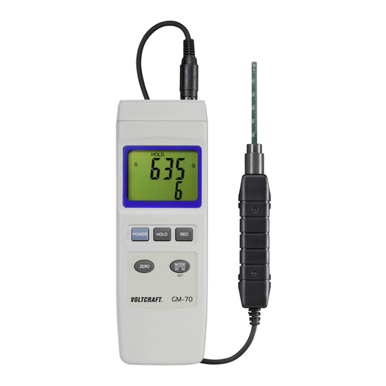
    7. Bedienelemente a) Messgerät 1 Taste ZERO 10 Netzteil-Anschlussbuchse DC 9V 2 Taste POWER 11 Batteriefachdeckel 3 LC-Display 12 Batteriefachschraube 4 Messbuchse für externen Sensor 13 Geräte-Aufstellbügel 5 Taste HOLD 14 Stativ-Buchse 6 Taste REC 15 Sensor-Kopf 7 Taste MODE -- DC AC (SET) 16 Schutzkappe (für den Sensor-Kopf) 8 RS232-Schnittstelle RS232 OUTPUT 17 Sensor-Griff...
  • Seite 8: Displaysymbole

    b) Displaysymbole Gauß, Natürliche Einheit der magnetischen Flussdichte Millitesla, SI-Einheit der magnetischen Flussdichte Zeigt positives Magnetfeld (Nordpol bei DC) Zeigt negatives Magnetfeld (Südpol bei DC) Zeigt den Wechselfeld-Modus an Anzeige für Datenaufzeichnung für Minimum-/Maximum-Wert Anzeige des Maximum-Wertes Anzeige des Minimum-Wertes Symbol niedrigen Batteriestands (Batteriewechsel erforderlich) c) Tastenfunktionen •...
  • Seite 9: Betrieb Mit Steckernetzteil

    b) Betrieb mit Steckernetzteil • Optional kann das Messgerät auch mit einem passenden Netzteil betrieben werden. Die 9 V Netzteil- Anschlussbuchse DC 9V (10) befindet sich auf der rechten Gehäuseseite unter einer Klappe. • Öffnen Sie die Klappe mit einem spitzen Gegenstand. Verbinden Sie den Niederspannungsstecker des passenden Steckernetzteils mit der Netzteil-Anschlussbuchse DC 9V (10) des Messgeräts.
  • Seite 10: Bedienung

    9. Bedienung a) Gerät ein- und ausschalten • Drücken Sie die Taste POWER (2), um das Gerät einzuschalten. Nach einer kurzen Initialisierungsphase ist das Messgerät betriebsbereit. Ein Piepton bestätigt das Einschalten. • Zum Ausschalten betätigen Sie die Taste POWER (2) erneut. Die Anzeige „OFF“ erscheint und schaltet das Gerät mit einem Piepton ab.
  • Seite 11: Kalibriereinstellung

    • Drücken und halten Sie die Taste MODE -- DC AC (7) für wenigstens 2 Sekunden, um in den Einstellungsmodus zu gelangen. Im Display erscheint zu Anfang „PoFF“. • Wählen Sie mit der Taste REC (6) den Menüpunkt „Unit“: Hier schalten Sie die Messeinheit um. •...
  • Seite 12: Hold-Funktion

    b) HOLD-Funktion • Drücken Sie im Messbetrieb die Taste HOLD (5), um den gegenwärtigen Messwert im LC-Display (3) festzuhalten. Das Symbol „HOLD“ wird im LC-Display angezeigt. • Ein erneutes Drücken der Taste HOLD (5) schaltet in den normalen Messmodus zurück. Das Symbol „HOLD“ erlischt.
  • Seite 13: Messen Von Ac-Magnetfeldern (Veränderlich)

    • Schalten Sie das Messgerät nach Messende aus. Wurde der Messbereich nach unten oder oben überschritten, so zeigt das LC-Display (3) „OL“ an. d) Messen von AC-Magnetfeldern (veränderlich) AC-Magnetfelder kommen in Wechselstromspulen wie z.B. Transformatoren etc. vor. Die magnetischen Feldlinien wechseln ihre Richtung.
  • Seite 14: E) Rec-Messwertspeicher

    e) REC-Messwertspeicher Der Messwertspeicher zeichnet die Minimum- und Maximum-Werte der Feldstärke auf. • Drücken Sie die Taste REC (6), um die REC-Funktion im Messbetrieb zu aktivieren. Im LC-Display (3) erscheint das Symbol „REC“ mit einem Piepton. Die Aufzeichnung der Messungen läuft. Maximalwerte •...
  • Seite 15: Zurücksetzen

    Das serielle Datensignal setzt sich aus 16 Bit mit folgender Reihenfolge zusammen: D15 D14 D13 D12 D11 D10 D9 D8 D7 D6 D5 D4 D3 D2 D1 D0 Startzeichen D11+D12 Messeinheit im Display: B5 = G, E3 = mT Polarität; 0 = positiv; 1 = negativ Dezimalpunkt (DP) an entsprechender Stelle von rechts nach links;...
  • Seite 16: Fehlerbehebung

    11. Fehlerbehebung Fehler Mögliche Ursache Abhilfe / Mögliche Lösung Das Messgerät lässt sich nicht Sind die Batterien verbraucht? Kontrollieren Sie den einschalten. Batteriezustand. Setzen Sie das Messgerät durch Drücken der Rückstelltaste RESET (9) zurück. Es wird kein stabiler Messwert Fehlmessung? Wird der Sensor zu Halten Sie den Sensor ruhig.
  • Seite 17: Technische Daten

    Ihre verbrauchten Batterien/Akkus können Sie unentgeltlich bei den Sammelstellen Ihrer Gemeinde, unseren Filialen oder überall dort abgeben, wo Batterien/Akkus verkauft werden. Sie erfüllen damit die gesetzlichen Verpflichtungen und leisten Ihren Beitrag zum Umweltschutz. 14. Technische Daten Spannungsversorgung ........9 V/DC (Alkaline-Batterie) AC/DC AP-9 VA (Netzteil nicht im Lieferumfang, ggf. separat zu erwerben) Eingangsstrom ..........15 mA (im Betrieb) Standby ............0,0 μA...
  • Seite 18 Table of contents Page Introduction ................................19 Explanation of symbols ............................19 Intended use ..............................20 Delivery content ..............................20 Features and functions ............................21 Safety information ..............................21 a) General information .............................21 b) Persons and product ...........................22 c) Battery .................................22 Operating elements ............................23 a) Measuring device ............................23 b) Display symbols ............................24 c) Button functions ............................24 Setup .................................24...
  • Seite 19: Introduction

    1. Introduction Dear customer, Thank you for purchasing this product. This product complies with statutory, national and European regulations. To ensure that the product remains in this state and to guarantee safe operation, always follow the instructions in these operating instructions. These operating instructions are part of this product.
  • Seite 20: Intended Use

    3. Intended use The magnetic field analysis device is intended for detecting magnetic DC and AC fields. It is a highly sensitive magnetic field measuring device for a wide range of applications in industry, development, electronics and mechanics. It is suitable for checking the function of energised coils, e.g. in relays, in solenoid valves, etc. Since it is a non-contact magnetic field analysis device, in most cases you will not need to open the housing to facilitate testing.
  • Seite 21: Features And Functions

    5. Features and functions • Versatile applicable in industry, materials research and laboratories • Separate sensor for easy operation and for remote measurement • Robust compact housing for secure transport • The highest possible accuracy through an integrated circuit • Extensive functions •...
  • Seite 22: B) Persons And Product

    • If you have any questions that are not answered in these operating instructions, please contact our technical customer service or other professionals. b) Persons and product • Never measure on bare, live wires. • Never use the product immediately after it has been brought from a cold room into a warm one. The condensation generated may destroy the product.
  • Seite 23: Operating Elements

    7. Operating elements a) Measuring device 1 ZERO button 10 DC 9 V power adapter connection socket 2 POWER button 11 Battery compartment cover 3 LC display 12 Battery compartment screw 4 Measurement socket for external sensor 13 Device stand 5 HOLD button 14 Tripod socket 6 REC button...
  • Seite 24: Display Symbols

    b) Display symbols Gauss, natural unit of magnetic flux density Millitesla, SI unit of magnetic flux density Indicates a positive magnetic field (north pole with DC) Indicates a negative magnetic field (south pole with DC) Indicates AC field mode Indicates minimum/maximum value data recording Indicates the maximum value Indicates the minimum value Low battery status symbol (battery required) c) Button functions • POWER button (2): Switches the measuring device on and off •...
  • Seite 25: B) Operation With A Power Adapter

    b) Operation with a power adapter • Optionally, the measuring device can be operated with a suitable power adapter. The 9 V power adaptor connection socket connection socket DC 9 V (10) is located under a flap on the right-hand side of the housing. • Open the flap with a pointed object. Connect the low voltage plug of the appropriate plug-in power adapter to the mains connection socket DC 9 V (10) on the measuring device.
  • Seite 26: Operation

    9. Operation a) Switch the device on and off • Press the POWER button (2) to switch on the device. After a brief initialisation phase, the measuring device is ready for operation. A beep confirms that it has been switched on. • Press the POWER button (2) once again to switch it off. ‘OFF’ appears on the display and the device switches off with a beep.
  • Seite 27: Calibration Setting

    • Use the REC button (6) to select the ‘Unit’ menu item. Here you can switch the unit of measurement. • Press the MODE - DC AC button (7) to select the unit of measurement. - t = millitesla (mT) - g = Gauss (g) •...
  • Seite 28: Hold Function

    b) HOLD function • In measuring mode, press the HOLD button (5) to freeze the current measured value on the LC display (3). The ‘HOLD’ symbol is shown on the LC display. • Pressing the HOLD button (5) again switches back to normal measuring mode. The ‘HOLD’ symbol goes out. c) Measuring DC magnetic fields (static) Magnets are, for example, permanent magnets with a north and south pole. The magnetic field lines run outside the magnet, always from the north pole to the south pole.
  • Seite 29: D) Measuring Ac Magnetic Fields (Changing)

    d) Measuring AC magnetic fields (changing) AC magnetic fields occur in AC coils such as transformers. The magnetic field lines change direction. The measuring device can measure AC fields from 50 Hz to 60 Hz. Proceeds as follows for AC measurement: • Switch on the measuring device. • Press the MODE - DC AC button (7) to switch through the measurement settings and resolutions. Each further press of the button switches one step further in the loop. Measuring mode for the AC fields is indicated with the display symbol ‘AC’. • Measurement settings c1 (resolution 0.1) and d1 (resolution 0.01) (see the figure below) are used for measurement of AC magnetic fields in unit mT. •...
  • Seite 30: Rec Measured Value Memory

    e) REC measured value memory The measured value memory records the minimum and maximum field strength values. • Press the REC button (6) to activate the REC function in measuring mode. ‘REC’ appears on the LC display (3) in conjunction with a beep. This indicates that measurement recording is active. Maximum values •...
  • Seite 31: Restoring The Default Settings

    The serial data signal is made up of 16 bits in the following order: D15 D14 D13 D12 D11 D10 D9 D8 D7 D6 D5 D4 D3 D2 D1 D0 Start signal D11+D12 United of measurement on the display: B5 = G, E3 = mT Polarity;...
  • Seite 32: Troubleshooting

    11. Troubleshooting Error Potential cause Remedy/potential solution The measuring device cannot be Are the batteries flat? Check the battery status. Reset the switched on. measuring device by pressing the RESET button (9). A stable measured value cannot be Wrong measurement? Has the Hold the sensor still. displayed.
  • Seite 33: Technical Specifications

    14. Technical specifications Power supply ............ 9 V/DC (alkaline battery) AC/DC AP-9 VA (power adaptor not included, must be purchased separately) Input current .............15 mA (in operation) Standby ............0.0 μA Battery life ............Approx. 9 hours in continuous use. Sensor ..............Hall effect sensor with automatic temperature compensation (ATC) Units of measurement ........G (Gauss), mT (millitesla) Fields ..............DC and AC field measurement Measurement ranges (DC) .......
  • Seite 34 Table des matières Page Introduction ................................35 Explication des symboles ..........................35 Utilisation prévue ...............................36 Contenu ................................36 Caractéristiques et fonctions ..........................37 Consignes de sécurité ............................37 a) Généralités ..............................37 b) Personnes et produit ...........................38 c) Piles/accus ..............................38 Nomenclature ..............................39 a) Instrument de mesure ..........................39 b) Symboles d'affichage ..........................40 c) Fonctions des touches ..........................40 Mise en service ..............................40...
  • Seite 35: Introduction

    1. Introduction Chers clients, Nous vous remercions d’avoir choisi ce produit. Ce produit est conforme aux exigences des normes européennes et nationales en vigueur. Afin de maintenir l’appareil en bon état et d’en assurer un fonctionnement sans danger, l’utilisateur doit impérativement respecter ce mode d’emploi ! Ce mode d’emploi fait partie intégrante du produit. Il contient des consignes importantes pour la mise en service et la manipulation du produit.
  • Seite 36: Utilisation Prévue

    3. Utilisation prévue L’analyseur de champ magnétique sert à contrôler des champs magnétiques continus et alternatifs. Il s’agit d’un instrument de mesure extrêmement sensible destiné à de nombreuses applications dans l'industrie, le développement, l'électronique et la mécanique. C’est l’instrument idéal pour contrôler le bon fonctionnement de bobines parcourues par un courant, par ex.
  • Seite 37: Caractéristiques Et Fonctions

    5. Caractéristiques et fonctions • Utilisation polyvalente dans l'industrie, la recherche sur les matériaux et les laboratoires • Sonde séparée pour un fonctionnement simple et les mesures à distance • Boîtier robuste et compact pour un transport sécurisé • Précision maximale grâce au circuit intégré •...
  • Seite 38: B) Personnes Et Produit

    • Si vous avez encore des questions auxquelles ce mode d'emploi n'a pas su répondre, nous vous prions de vous adresser à notre service technique ou à un expert. b) Personnes et produit • N’effectuez jamais de mesures sur des conducteurs dénudés sous tension. •...
  • Seite 39: Nomenclature

    7. Nomenclature a) Instrument de mesure 1 Touche ZERO 10 Prise du bloc d’alimentation DC 9 V 2 Touche POWER 11 Couvercle du compartiment des piles 3 Écran à CL 12 Vis du compartiment des piles 4 Borne pour sonde externe 13 Pied d'appui de l'appareil 5 Touche HOLD 14 Douille pour trépied...
  • Seite 40: Symboles D'affichage

    b) Symboles d'affichage Gauss, unité naturelle de l'induction magnétique Millitesla, unité SI de l'induction magnétique Indique le champ magnétique positif (pôle nord pour DC) Indique le champ magnétique négatif (pôle sud pour DC) Indique le mode de champ alternatif Indique l'enregistrement des données pour la valeur minimale/maximale Affichage de la valeur maximale Affichage de la valeur minimale Symbole de pile faible (remplacement de la pile nécessaire)
  • Seite 41: Fonctionnement Avec Bloc D'alimentation

    b) Fonctionnement avec bloc d'alimentation • En option, vous pouvez utiliser l'appareil de mesure aussi avec un bloc d'alimentation approprié. La prise pour le bloc d'alimentation 9 V DC 9 V (10) se trouve sur le côté droit du boîtier sous un clapet. •...
  • Seite 42: Utilisation

    9. Utilisation a) Allumer et éteindre l’appareil • Appuyez sur la touche POWER (2) afin d’allumer l’appareil. Après une brève phase d'initialisation, l'appareil de mesure est prêt à fonctionner. La mise en marche est confirmée par un bip sonore. • Pour éteindre l’instrument, appuyez à nouveau sur la touche POWER (2). L'affichage « OFF » apparaît et l'appareil s'arrête en émettant un bip sonore. À la fin de la mesure, éteignez toujours l’appareil. b) Réglages avancés • Appuyez sur la touche MODE -- DC AC (7) et maintenez-la enfoncée pendant env. 2 secondes pour accéder aux réglages avancés.
  • Seite 43: D) Réglage De La Calibration

    • Avec la touche REC (6), sélectionnez le sous-menu « Unit ». C’est ici que vous pouvez changer d’unité de mesure. • Appuyez sur la touche MODE -- DC AC (7) pour sélectionner l’unité de mesure. - t = Millitesla (mT) - g = Gauss (g) •...
  • Seite 44: B) Fonction De Maintien - Hold

    b) Fonction de maintien - HOLD • En mode de mesure, appuyez sur la touche HOLD (5) pour que la valeur de mesure actuelle reste affichée sur l'écran LCD (3). Le symbole « HOLD » s’affiche sur l'écran. • Appuyez à nouveau sur la touche HOLD (5) pour retourner au mode de mesure normal. Le symbole « HOLD » disparaît. c) Mesure des champs magnétiques DC (statiques) Les aimants sont par ex.
  • Seite 45: D) Mesure Des Champs Magnétiques Ac (Variables)

    d) Mesure des champs magnétiques AC (variables) Les champs magnétiques AC se retrouvent dans les bobines à courant alternatif telles que les transformateurs, etc. Les lignes de champ magnétique changent leur direction. L'instrument peut mesurer des champs magnétiques alternatifs de 50 Hz à 60 Hz. Pour la mesure AC, procédez comme suit : •...
  • Seite 46: Mémoire Des Valeurs Mesurées Rec

    e) Mémoire des valeurs mesurées REC La mémoire des valeurs mesurées permet d’enregistrer les valeurs minimales et maximales de l'intensité du champ. • Appuyez sur la touche REC (6) pour activer la fonction REC lors des mesures. Le symbole « REC » s’affiche sur l’écran LCD avec un bip sonore. L'enregistrement des mesures est en cours. Valeurs maximales •...
  • Seite 47: G) Réinitialisation

    Le signal de données sériel se compose de 16 bits présentant la séquence suivante : D15 D14 D13 D12 D11 D10 D9 D8 D7 D6 D5 D4 D3 D2 D1 D0 Signe de départ D11+D12 Unité de mesure à l'écran : B5 = G, E3 = mT Polarité...
  • Seite 48: Dépannage

    11. Dépannage Problème Cause possible Action corrective / Solution possible L'appareil de mesure ne s'allume Les piles sont-elles vides ? Contrôlez le niveau de charge des pas. piles. Réinitialisez l'appareil de mesure en appuyant sur la touche de réinitialisation RESET (9). Aucune valeur de mesure stable ne Erreur de mesure ? La sonde bouge Maintenez la sonde immobile.
  • Seite 49: Données Techniques

    Vous pouvez rapporter gratuitement vos piles/accumulateurs usagées aux centres de récupération de votre commune, à nos succursales ou à tous les points de vente de piles/accumulateurs. Vous respectez ainsi les ordonnances légales et contribuez à la protection de l’environnement. 14. Données techniques Alimentation électrique ........
  • Seite 50 Inhoudsopgave Pagina Inleiding ................................51 Verklaring van de symbolen ..........................51 Doelmatig gebruik ..............................52 Leveringsomvang ..............................52 Eigenschappen en functies ..........................53 Veiligheidsinstructies ............................53 a) Algemeen ..............................53 b) Personen en product ...........................54 c) Batterij/accu ..............................54 Bedieningselementen ............................55 a) Meetapparaat ..............................55 b) Displaypictogrammen ..........................56 c) Toetsfuncties ..............................56 Ingebruikname ..............................56 a) Plaatsen/vervangen van de batterij ......................56 b) Gebruik met netspanningsadapter ......................57...
  • Seite 51: Inleiding

    1. Inleiding Geachte klant, Hartelijk dank voor de aankoop van dit product. Dit product voldoet aan alle wettelijke, nationale en Europese normen. Om dit zo te houden en een veilig gebruik te garanderen, dient u als gebruiker de aanwijzingen in deze gebruiksaanwijzing op te volgen.
  • Seite 52: Doelmatig Gebruik

    3. Doelmatig gebruik De magneetveldmeter dient voor het meten van magnetische gelijk- en wisselvelden. Het is een hooggevoelige magneetveldmeter voor uiteenlopende toepassingen in de industrie, ontwikkeling, elektronica en mechanica. Het is geschikt voor het testen van de werking van onder stroom staande spoelen zoals bijv. in relais en magneetventielen. De magneetveldmeter werkt contactvrij, zodat de behuizingen meestal gesloten kunnen blijven.
  • Seite 53: Eigenschappen En Functies

    5. Eigenschappen en functies • Veelzijdig toepasbaar in de industrie, bij materiaalonderzoek en in laboratoria • Aparte sensor voor eenvoudig gebruik en meting op afstand • Robuuste, compacte behuizing, veilig te vervoeren • De grootst mogelijke nauwkeurigheid door geïntegreerde circuits •...
  • Seite 54: B) Personen En Product

    • Onderhoud, aanpassingen en reparaties mogen alleen uitgevoerd worden door een vakman of in een daarin gespecialiseerde werkplaats. • Als u nog vragen heeft die niet door deze gebruiksaanwijzing zijn beantwoord, neem dan contact op met onze technische dienst of andere specialisten. b) Personen en product •...
  • Seite 55: Bedieningselementen

    7. Bedieningselementen a) Meetapparaat 1 Toets ZERO 10 Aansluitbus netspanningsadapter DC 9 V 2 Toets POWER 11 Batterijvakdeksel 3 Lcd-display 12 Batterijvakschroef 4 Aansluiting voor externe sensor 13 Beugel apparaat 5 Toets HOLD 14 Statief-bus 6 Toets REC 15 Sensorkop 7 Toets MODE -- DC AC (SET) 16 Beschermkap (voor de sensorkop) 8 RS232-poort RS232 OUTPUT...
  • Seite 56: B) Displaypictogrammen

    b) Displaypictogrammen Gauss, natuurlijke eenheid aan de magnetische fluxdichtheid Millitesla, SI-eenheid van magnetische fluxdichtheid Toont een positief magnetisch veld (noordpool bij DC) Toont een negatief magnetisch veld (zuidpool bij DC) Toont de modus wisselveld Aanduiding voor gegevensregistratie voor minimum/maximum waarde Indicatie van de maximale waarde Indicatie van de minimale waarde Symbool lage batterijstatus (wisselen van de batterij nodig) c) Toetsfuncties •...
  • Seite 57: B) Gebruik Met Netspanningsadapter

    b) Gebruik met netspanningsadapter • Als optie kan het meetapparaat ook worden gebruikt in combinatie met een geschikte netspanningsadapter. De 9 V-aansluitbus DC 9 V (10) voor de netspanningsadapter bevindt zich aan de rechterzijde van het apparaat onder een klepje. •...
  • Seite 58: Bediening

    9. Bediening a) Het apparaat aan- en uitzetten • Druk op de toets POWER (2) om het apparaat in te schakelen. Na een korte initialiseringsfase is het meetapparaat klaar voor gebruik. Een pieptoon bevestigt het inschakelen. • Druk opnieuw op de toets POWER (2) om het apparaat uit te schakelen. De weergave "OFF" verschijnt en het apparaat schakelt met een pieptoon uit.
  • Seite 59: D) Kalibratie-Instelling

    • Kies met de toets REC (6) het menupunt "Unit": Hier kunt u de meeteenheid omschakelen. • Druk op de toets MODE -- DC AC (7) om de meeteenheid te kiezen. - t = millitesla (mT) - g = gauss (g) •...
  • Seite 60: B) Hold-Functie

    b) HOLD-functie • Druk in de meetmodus op de toets HOLD (5) om de actuele meetwaarde in het lcd-display (3) vast te houden. Het symbool "HOLD" wordt op het lcd-display weergegeven. • Door het opnieuw drukken op de toets HOLD (5) verschijnt de normale meetmodus weer. Het symbool "HOLD" verdwijnt.
  • Seite 61: D) Meten Van Ac-Magneetvelden (Wisselvelden)

    • Schakel het meetapparaat na beëindiging van de meting uit. Wordt het meetbereik naar beneden of boven overschreden, dan geeft het lcd-display (3) "OL" aan. d) Meten van AC-magneetvelden (wisselvelden) AC-magnetische velden komen voor in wisselstroomspoelen zoals in transformatoren. De magnetische veldlijnen wisselen van richting.
  • Seite 62: E) Rec-Meetwaardegeheugen

    e) REC-meetwaardegeheugen Het meetwaardegeheugen registreert de minimum- en maximumwaarden van de veldsterkte. • Druk op de toets REC (6) om de REC-functie bij het meten te activeren. In het lcd-display (3) verschijnt het symbool "REC" met een pieptoon. De registratie van de metingen loopt. Maximale waarden •...
  • Seite 63: G) Terugzetten

    Het seriële datasignaal bestaat uit 16 bits met de volgende sequentie: D15 D14 D13 D12 D11 D10 D9 D8 D7 D6 D5 D4 D3 D2 D1 D0 Startbit D11+D12 Meeteenheid op het display: B5 = G, E3 = mT Polariteit; 0 = positief, 1 = negatief Decimale punt (DP) op de overeenkomstige positie van rechts naar links;...
  • Seite 64: Verhelpen Van Storingen

    11. Verhelpen van storingen Storing Mogelijke oorzaak Uitkomst / mogelijke oplossing Het meetapparaat kan niet worden Is de batterij leeg? Controleer de toestand van de ingeschakeld. batterij. Herstel het meetapparaat terug naar de fabrieksinstellingen. Druk hiervoor op de toets RESET (9). Er verschijnt geen stabiele Meetfout? Wordt de sensor te Houd de sensor stil tijdens het...
  • Seite 65: Technische Gegevens

    Batterijen/accu’s die schadelijke stoffen bevatten, zijn gemarkeerd met nevenstaand symbool. Deze mogen niet met het huisvuil worden afgevoerd. De aanduidingen voor de zware metalen zijn: Cd = cadmium, Hg = kwik, Pb = lood (de aanduiding staat op de batterijen/accu’s bijv. onder het links afgebeelde vuilnisbaksymbool).
  • Seite 66 Dies ist eine Publikation der Conrad Electronic SE, Klaus-Conrad-Str. 1, D-92240 Hirschau (www.conrad.com). Alle Rechte einschließlich Übersetzung vorbehalten. Reproduktionen jeder Art, z. B. Fotokopie, Mikroverfilmung, oder die Erfassung in elektronischen Datenverarbeitungsanlagen, bedürfen der schriftlichen Genehmigung des Herausgebers. Nachdruck, auch auszugsweise, verboten. Die Publikation entspricht dem technischen Stand bei Drucklegung. Copyright 2019 by Conrad Electronic SE.

Inhaltsverzeichnis