Videotec MAXIMUS MHX Bedienungsanleitung
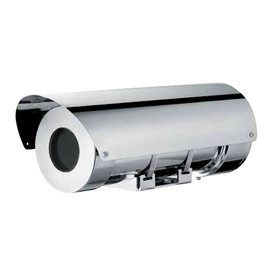
Explosion-proof stainless steel housing
Vorschau ausblenden
Andere Handbücher für MAXIMUS MHX:
- Handbuch (46 Seiten) ,
- Bedienungsanleitung (284 Seiten)

Verwandte Anleitungen für Videotec MAXIMUS MHX


Inhaltszusammenfassung für Videotec MAXIMUS MHX
- Seite 1 MAXIMUS MHX, MAXIMUS MHXT Explosion-proof stainless steel housing English - Instructions manual Italiano - Manuale di istruzioni Français - Manuel d’instructions Deutsch - Bedienungslanleitung Русский - Руководство по эксплуатации...
- Seite 141 MAXIMUS MHX, MAXIMUS MHXT Explosionsgeschütztes Gehäuse aus rostfreiem Stahl Deutsch - Bedienungslanleitung...
- Seite 143 Inhaltsverzeichnis DEUTSCH 1 Allgemeines ........................7 1.1 Schreibweisen ................................7 2 Anmerkungen zum Copyright und Informationen zu den Handelsmarken ..... 7 3 Sicherheitsnormen ......................7 3.1 Details der ATEX-IECEX-Bescheinigung ......................9 3.1.1 Temperatur: ....................................9 3.1.2 Installationsanleitungen ............................... 9 3.1.3 Montageanleitungen ................................9 3.1.4 Besondere Bedingungen für die sichere Anwendung .....................10 3.1.5 Zusätzliche Informationen ..............................10 4 Identifizierung ......................
- Seite 144 7.3.4 Installation von Kamera/ Optik............................24 7.3.5 Anschluss der Videokamera an die Stromversorgung .....................25 7.3.5.1 Anschluss der Videokamera an die Stromversorgung in 12Vdc und 24Vac (ohne Netzteil) ...........25 7.3.5.2 Anschluss der Videokamera an die Stromversorgung in 120Vac und 230Vac (ohne Netzteil) ........25 7.3.5.3 Anschluss der Videokamera an die Stromversorgung in 12Vdc, 24Vac, 120Vac und 230Vac (mit Netzteil) ....26 7.3.6 Ausgang des Videosignals einer analogen Videokamera.
- Seite 145 13.2.2 Mechanik ....................................40 13.2.3 Elektrik.....................................40 13.2.4 Umgebung ....................................40 13.2.5 Zertifizierungen ...................................40 13.2.6 Halterungen und Adapter ..............................40 13.2.7 Zubehör ....................................40 13.3 Stromverbrauch ..............................41 13.4 Kabelverschraubungen .............................41 14 Technische Zeichnungen................... 42 A Anhang - Gasgruppen Klassifizierung ............... 44 MNVCMHX_1432_DE...
- Seite 146 MNVCMHX_1432_DE...
-
Seite 147: Allgemeines
1 Allgemeines 3 Sicherheitsnormen Lesen Sie bitte vor dem Installieren und dem Der Hersteller lehnt jede Haftung für Verwenden dieses Gerätes die Bedienungsanleitung eventuelle Schäden ab, die aufgrund sorgfältig durch. Bewahren Sie sie zum späteren unsachgemäßer Anwendung der in diesem Nachschlagen auf. - Seite 148 • Um das Risiko von Zündung durch Kontakt mit • Die hintere Flansche darf nur geöffnet werden, explosionsgefährdeten Zone muss das Gerät vor um die Verkabelung der Vorrichtung auszuführen. dem Öffnen vom Versorgungskreislauf abgetrennt Die anderen Flanschen dürfen nur vom Hersteller werden.
-
Seite 149: Details Der Atex-Iecex-Bescheinigung
3.1 Details der ATEX-IECEX-Bescheinigung 3.1.1 Temperatur: Das Verhältnis zwischen Raumtemperatur, Gasaggregaten und EX-Kennzeichnung ist hier angegeben: Umgebungstemperatur Gasgruppe Kennzeichnung EX -40°C to +60°C II 2 G Ex d IIB T6 Gb Ta -40°C to +60°C -20°C to +60°C II 2 G Ex d IIC T6 Gb Ta -20°C to +60°C -40°C to +60°C II 2 G Ex d IIC T6 Gb Ta -40°C to +60°C Tab. -
Seite 150: Besondere Bedingungen Für Die Sichere Anwendung
3.1.4 Besondere Bedingungen für die sichere Anwendung • Um den Schutzgrad IP66/IP67 am Eingang aufrecht zu erhalten muss bei jedem Öffnen des hinteren Flansches der O-Ring durch einen Neuen ersetzt werden. • Die höchstzulässigen Spaltweiten (ic) sind geringer als wie in Tabelle 2 der EN 60079-1:2007 gefordert wird. Gemäß... -
Seite 151: Identifizierung
4 Identifizierung Im hinteren Flansch ist der Innenschlitten eingebaut, auf dem die Videokamera positioniert werden muss; er enthält auch den Steuerteil der internen Elektronik, 4.1 Beschreibung und der die Versorgung und die Heizvorrichtungen des Bezeichnung des Produktes Gehäuses steuert. Der Eingang der Kabel erfolgt über zwei Das explosionssichere Gehäuse der Serie MHX wurde Gewindebohrungen 3/4"... -
Seite 152: Kennzeichnung Des Produkts
4.2 Kennzeichnung des Produkts Abb. 2 CE-Kennzeichnung und Nummer der benannten Seriennummer (Jede vom Hersteller nicht Stelle für die Überprüfung der Konformität der ausdrücklich genehmigte Veränderung führt Produktion. zum Verfall der Gewährleistungsrechte.) Name und Adresse des Herstellers Versorgungsspannung (V) Identifizierungscode des Modells Absorptionsstrom (A) Umgebungsbetriebstemperatur bezüglich Frequenz (Hz) -
Seite 153: Atex-Zertifizierung
11. ATEX-Zertifizierung: • Kennzeichnungsnummer ATEX • Klassifizierung des Zonentyps, Schutzmethode, Temperaturklasse für die die Verwendung dieses Produktes gemäß der Richtlinie ATEX zugelassen ist. KENNZEICHNUNG ATEX Umgebungstem- Gaskennzeichnung Staubkennzeichnung peratur sgrup- -40°C to +60°C II 2 G Ex d IIB T6 Gb Ta -40°C to +60°C II 2 D Ex tb IIIC T85°C Db Ta -40°C to +60°C -20°C to +60°C II 2 G Ex d IIC T6 Gb Ta -20°C to +60°C... -
Seite 154: Versionen
5.3 Fensterscheibe aus 5 Versionen Germanium 5.1 Getempertes Glas Das Schutzgitter muss immer vorhanden Für die Ausführung wurde Hartglas ausgewählt, um sein, wenn die Einheit in Betrieb ist. heftigen Stößen standzuhalten. Die Version ist mit Fensterscheibe aus Germanium ausgestattet, die eigens für Anlagen mit Wärmebildkameras ausgelegt ist. -
Seite 155: Vorbereitung Des Produktes Auf Den Gebrauch
6 Vorbereitung des Das Gerät ist nur als deaktiviert zu Produktes auf den definieren, wenn die Versorgung abgetrennt ist und die Anschlusskabel an Gebrauch andere Vorrichtungen entfernt wurden. Der Einbau soll mit einer Jede Art von Änderung, die nicht Absperrvorrichtung ausgestattet sein , die ausdrücklich vom Hersteller gebilligt im Notfall sofort erkennbar und benutzbar wurde, lässt die Garantie und die... -
Seite 156: Entfernen Der Verpackung
6.2 Entfernen der Verpackung 6.4 Auf die Installation und Inhalt vorbereitende Tätigkeiten 6.2.1 Entfernen der Verpackung Die Installation mit geeigneten Werkzeugen ausführen. Dennoch kann der Ort, an dem Bei der Lieferung des Produktes ist zu prüfen, ob die die Vorrichtung installiert wird, den Einsatz Verpackung intakt ist oder offensichtliche Anzeichen von Spezialwerkzeugen erfordern. -
Seite 157: Befestigung An Der Brüstung
6.4.1 Befestigung an der Brüstung 6.4.2 Befestigung mit Bügel Zunächst den Sockel des Adapters am endgültigen Die Halterung kann direkt an einer vertikalen Bestimmungsort befestigen. Schrauben verwenden, Wand befestigt werden. Schrauben und die einem Gewicht standhalten können, das Wandbefestigungsvorrichtungen verwenden, die mindestens 4 mal größer als das der Einheit ist. -
Seite 158: Befestigung Durch Mastverseilung Oder Winkeladaptermodul
6.4.3 Befestigung durch Mastverseilung 6.4.3.2 Befestigung mit Winkelmodul oder Winkeladaptermodul Um den Halterungsbügel am Winkeladaptermodul zu befestigen verwendet man 4 flache Um das Gehäuse an der Mastverseilung zu Unterlegescheiben, 4 Grower-Unterlegescheiben aus installieren bzw. in Übereinstimmung eines Winkels Edelstahl und 4 Sechskantschrauben aus Edelstahl muss es in erster Linie an der Wandhalterung (A4 Klasse 80) M10x30mm. -
Seite 159: Zusammenbau Und Installation
Sicherstellen, dass die Installation gemäß Abb. 13 der lokalen Normen ausgeführt wurde. 7.2.6 Befestigung des Wischerblattes VIDEOTEC empfiehlt, vor der endgültigen Montage Das Wischerblatt auf die Welle des Scheibenwischers am Installationsort die Konfiguration und die setzen. Leistungen des Gerätes in einer Werkstatt oder Die Bürste der Scheibenwischer mit den... -
Seite 160: Öffnung Des Schutzgehause
7.3 Installation 7.3.1 Öffnung des Schutzgehause Für die Installation der Videokamera muss der hintere Bevor man technische Eingriffe oder Boden des Gehäuses geöffnet werden. Wartungsoperationen am Gerät ausführt, Die Befestigungsschrauben M6 des Bodens lösen und muss sichergestellt werden, dass die Zone aus dem Gehäusekörper herausziehen, dazu die 3 nicht potenziell explosionsgefährdet Sechskant-Abziehschrauben M5x60mm verwenden. -
Seite 161: Kabeleingang
7.3.2 Kabeleingang 7.3.3 Anschluss der Stromversorgung Um den Durchgang von Flammen oder Explosionen Die elektrischen Anschlüsse nur von der Vorrichtung auf das Leitungssystem oder die durchführen, wenn die Stromversorgung Kabelverschraubung und von diesen wiederum auf abgetrennt und die Trennvorrichtung offen die Außenumgebung zu verhindern, muss man einen ist. -
Seite 162: Anschluss Der Versorgungsleitung In 12Vdc Und 24Vac (Ohne Netzteil)
7.3.3.1 Anschluss der Versorgungsleitung in Sicherstellen, dass der Überbrückungsstecker in seinem Verbindungsstecker J4 an der Karte montiert 12Vdc und 24Vac (ohne Netzteil) ist. Die Kabel im Gehäuse müssen ziemlich lang gehalten werden, damit sie an den entsprechenden Klemmen mit einer Quetschtzange montiert werden können. -
Seite 163: Anschluss Der Versorgungsleitung In 120Vac Und 230Vac (Ohne Netzteil)
7.3.3.2 Anschluss der Versorgungsleitung in ANSCHLUSS DER STROMVERSORGUNG 120Vac und 230Vac (ohne Netzteil) Farbe Klemmen Netzteil 230Vac Die Kabel im Gehäuse müssen ziemlich lang gehalten werden, damit sie an den Blau (N) Nullleiter entsprechenden Klemmen mit einer Braun (L) Phase Quetschtzange montiert werden können. -
Seite 164: Anschluss Der Versorgungsleitung In 12Vdc, 24Vac, 120Vac Und 230Vac (Mit Netzteil)
7.3.3.3 Anschluss der Versorgungsleitung 7.3.4 Installation von Kamera/ Optik. in 12Vdc, 24Vac, 120Vac und 230Vac (mit Videokamera/Optik auf dem internen Schlitten Netzteil) montieren; dazu die mitgelieferten Schrauben und Abstandstücke verwenden, damit die Die Kabel im Gehäuse müssen ziemlich Installationshöhe eine perfekte Sicht aus dem Fenster lang gehalten werden, damit sie an den garantiert. -
Seite 165: Anschluss Der Videokamera An Die Stromversorgung
7.3.5 Anschluss der Videokamera an die 7.3.5.2 Anschluss der Videokamera an die Stromversorgung in 120Vac und 230Vac Stromversorgung (ohne Netzteil) Eine fehlerhafte Verkabelung der In diesen Ausführungen ist die Versorgung kann die Videokamera Eingangsspannung gleich der irreversibel beschädigen. Versorgungsspannung von Kamera/Optik. Die Versorgung mithilfe der mitgelieferten Den abnehmbaren Stecker aus der Karte ausziehbaren Verbindungsstecker ausführen. -
Seite 166: Anschluss Der Videokamera An Die Stromversorgung In 12Vdc, 24Vac, 120Vac Und 230Vac (Mit Netzteil)
7.3.5.3 Anschluss der Videokamera an die 7.3.6 Ausgang des Videosignals einer Stromversorgung in 12Vdc, 24Vac, 120Vac analogen Videokamera. und 230Vac (mit Netzteil) Die Anlage gehört zum Typ CDS (Cable Den abnehmbaren Stecker aus der Karte Distribution System), nicht an Kreisläufe herausziehen. -
Seite 167: Anschluss Glasfaserkabel
7.3.7 Anschluss Glasfaserkabel Für Sender auf Single Mode Faser, verwenden Sie Faser 9/125µm mit max. Länge von 69km. Einen für das Modell des installierten Den Lichtwellenleiter entlang der Empfängers geeigneten Glasfasertyp Eingangsvorrichtung schieben. verwenden. Das Glasfaserkabel mit einem Stecker Typ ST Die Übertragung von Videos und Daten erfolgt mit anköpfen. -
Seite 168: Ausgang Des Signals Einer Videokamera Ip
Wenn eine Videokamera IP mit Ausgang RS-485, Die Übertragung der Telemetrie und des mit Protokoll PELCO D (2400baud, 9600baud) Videosignals erfolgt über das Ethernet- oder VIDEOTEC MACRO (9600baud, 38400baud) Netzkabel. Wenn die Videokamera verwendet wird, kann dieser Kanal ausgenutzt einen Ausgang RS-485 besitzt, siehe werden, um Telemetriebefehle zu senden.. -
Seite 169: Anschluss Der Seriellen Linie
RS-485 vor. Der Linienbetrieb erfolgt über das AGND Referenz Linie Protokoll PELCO D (2400baud, 9600baud) oder RS-485 VIDEOTEC MACRO (9600baud, 38400baud), maximale Tab. 8 Entfernung von 1200m. Den verkabelten Verbindungsstecker im Stecker einfügen und die Kabel mit einer Schelle verbinden. -
Seite 170: Spezialbefehle
Adresse – – – Adresse 31 Baud rate – – – – – – – 9600baud (PELCO D), 38400baud (VIDEOTEC MACRO) Baud rate – – – – – – – 2400baud (PELCO D), 9600baud (VIDEOTEC MACRO) Protokoll – – –... -
Seite 171: Aktivierung Der Scheibenwischer
7.3.12 Aktivierung der Scheibenwischer 7.3.12.2 Aktivierung über die Tastatur Wenn eine serielle Kommunikationslinie verwendet 7.3.12.1 Aktivierung über die ferngesteuerte wird, kann der Scheibenwischer über die Tastatur Taste aktiviert werden. Der Wiper kann ferngesteuert über einen 7.3.13 Aktivierung der Waschanlage potenzialfreien Kontakt NO (normalerweise über die Tastatur geöffnet) aktiviert werden . -
Seite 172: Aktivierung Eines Externen Scheinwerfers Über Den Ausgang Day/Night Der Videokamera
7.3.14 Aktivierung eines externen Den abnehmbaren Stecker J5 (OUT_Day/Night) aus der CPU-Karte herausziehen und die Relaiskabel Scheinwerfers über den Ausgang day/ anschließen. night der Videokamera Den verkabelten Verbindungsstecker in der Karte Die Videokamera könnte mit einem Ausgang day/ einfügen und die Kabel mit einer Schelle verbinden. night mit potenzialfreiem Kontakt versehen sein, der für die Aktivierung eines externen Scheinwerfers verwendet werden kann. -
Seite 173: Schließen Des Gehäuses
7.3.15 Schließen des Gehäuses Den Boden in den Gehäusekörper einfügen, dabei die Schließbohrungen des Bodens mit denen des Sicherstellen, dass die Funktionstüchtigkeit Gehäusekörpers ausrichten. des Systems positiven Ausgang hat, bevor Darauf achten, die O-Ring-Dichtung nicht man das Gehäuse schließt und das Gerät zu beschädigen. -
Seite 174: Anleitung Für Einen Sicheren Betrieb
8 Anleitung für einen 8.1.3 Vorschriften zur Vorbeugung von Explosionen sicheren Betrieb Entsprechendes Werkzeug für die Eingriffe in der jeweiligen Zone verwenden. 8.1 Betrieb unter sicheren Denken Sie daran, dass die Vorrichtung an eine Bedingungen entsprechende elektrische Erdungsleitung angeschlossen werden muss. Bevor man folgendes ausführt, Bevor man technische Eingriffe am Gerät vornimmt muss sichergestellt werden, dass die... -
Seite 175: Wartung Und Reinigung
Einheit in Betrieb ist. durch den Benutzer Das Schutzgitter entfernen, dazu die 4 Schrauben Wenn der Kundendienst von VIDEOTEC kontaktiert und die Unterlegscheiben an der Vorderseite des wird, muss die Seriennummer zusammen mit dem Gehäuses mit einem funkensicherem Werkzeug Identifizierungscode des Gerätes angegeben werden. -
Seite 176: Wechsel Der Sicherungen
Sicherung muss den Angaben der Tabelle entsprechen. Im Falle von Beschädigungen muss WECHSEL DER SICHERUNGEN das Auswechseln oder die Reparatur der betreffenden Teile von VIDEOTEC Spannung Sicherung (FUS1) ausgeführt werden bzw. unter ihrer 12Vdc T 4A H 250V 5x20 Aufsicht. -
Seite 177: Müllentsorgungsstellen
11 Müllentsorgungsstellen 12 Troubleshooting Fordern Sie Fachleute für die Arbeiten an, wenn: Dieses Symbol und das entsprechende • Die Einheit nach einem Sturz beschädigt ist; Recycling-System gelten nur für EULänder und finden in den anderen Ländern der • Die Leistungen der Einheit merklich abgefallen Welt keine Anwendung. -
Seite 178: Technische Daten
13.1 MHX 13 Technische Daten 13.1.1 Allgemeines Falls das Gerät mit aggressiven Substanzen in Kontakt kommt, ist der Benutzer dafür verantwortlich, Hergestellt aus rostfreiem Stahl AISI 316 entsprechende Vorsichtsmaßnahmen zu ergreifen, Externe Oberflächen passiviert und elektropoliert um einer Beschädigung vorzubeugen und die Dichtung O-Ring aus Silikon Schutzvorrichtungen nicht zu beeinträchtigen. -
Seite 179: Umgebung
13.1.4 Umgebung 13.1.6 Zubehör Innen/Außen OCTEX3/4C Kabelschelle mit Gummidichtung EX 3/4" NPT Installation- und Betriebstemperatur: -40°C/+60°C nicht armiertes Kabel IECEX- Impulsfestigkeit: bis zu 2 kV Leitung zu Leitung, bis zu ATEX-GOST 4 kV zwischen Leitung und Erde (EN61000-4-5 level 4) OCTEXA3/4C Kabelschelle mit 13.1.5 Zertifizierungen... -
Seite 180: Mhxt
13.2 MHXT 13.2.5 Zertifizierungen ATEX (EN 60079-0: 2012, EN 60079-1: 2007, EN 60079- 13.2.1 Allgemeines 31: 2009) Hergestellt aus rostfreiem Stahl AISI 316 • b II 2 G Ex d IIB T6 Gb Ta -40°C to +60°C or Externe Oberflächen passiviert und elektropoliert •... -
Seite 181: Stromverbrauch
13.3 Stromverbrauch STROMVERBRAUCH Versorgungsspannung Max. elektrischer Verbrauch (ein- Max. Verlustleistung der vom Kunden schließlich Verbrauch von Kamera/ installierten Videokamera/Optik. Optik und der Heizung) 230Vac 0.34A, 50/60Hz, 80W 120Vac 0.5A, 50/60Hz, 60W 24Vac 2.2A, 50/60Hz, 53W 12Vdc 2.8A, 34W Tab. 12 13.4 Kabelverschraubungen AUSWAHLSCHEMA 3/4"... -
Seite 182: Technische Zeichnungen
14 Technische Zeichnungen Die Abmessungen der Zeichnungen sind in Millimeter angegeben. Ø 102 NUTZFLÄCHE Ø 75 Ø 75 NUTZ- FLÄCHE 139.5 Abb. 50 MAXIMUS MHX. MNVCMHX_1432_DE... - Seite 183 Ø 102 NUTZFLÄCHE Ø 56 NUTZ- FLÄCHE 139.5 Abb. 51 MAXIMUS MHXT. MNVCMHX_1432_DE...
-
Seite 184: A Anhang - Gasgruppen Klassifizierung
A Anhang - Gasgruppen Klassifizierung Die nachstehende Tabelle zeigt die Einteilung einiger Gase und Dämpfe nach Explosionsschutzgruppen und Temperaturen. Ein vollständiges Verzeichnis enthalten IEC/EN 60079-12 und IEC/EN 60079-20. GASGRUPPEN KLASSIFIZIERUNG Temperaturklassifizierung (Maximale oberflächliche Temperatur des Gehäuses) 1 Gruppe T1 450°C 300°C 200°C 135°C...